Установка прошивки WLED на ESP32 и ESP8266. Интеграция WLED в Home Assistant
WLED – это прошивка для микроконтроллеров ESP32 и ESP8266 которая специализируется на управлении адресными светодиодами WS2812. В данной прошивке очень большое количество разных готовых световых эффектов и очень много еще разных настроек. Управляется все это дело либо через web страницу либо через приложение на смартфоне. И даже существует специальная интеграция в Home Assistant для управления WLED.
Вот в этой статье кратко покажу как установить WLED на Ваш микроконтроллер и начать пользоваться этой замечательной прошивкой.
Для начала нам нужно скачать последнюю версию прошивки в формате .bin с странички проекта: https://github.com/Aircoookie/WLED/releases
После скачивания .bin файла нам нужно этот файл “залить” в espшку. Заливка немного отличается друг от друга у контроллеров esp32 и esp8266.
Скачиваем программу FLASH DOWNLOAD Tool. Можно скачать прям с официального сайта последнюю версию: https://www.espressif.com/en/support/download/other-tools
После этого запускаем программу выбираем какой контроллер будем использовать:
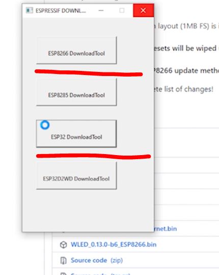
После этого откроется меню загрузки. Сначала покажу загрузку для ESP32 и выглядит оно так:
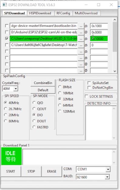
Здесь нас интересует только зеленым выделенное. А именно Сначала мы выбрали .bin файл скаченный. И напротив ему выбрали адрес. Он тут 0x10000. Такой адрес используется для ESP32. Все остальное оставляем без изменений, я имею ввиду все галочки. Только выбрать нужно COM порт. У меня сейчас стоит COM1. Ну и для загрузки прошивки теперь, нам нужно нажать кнопку IDLE. И начнется загрузка прошивки.
Теперь для ESP8266:
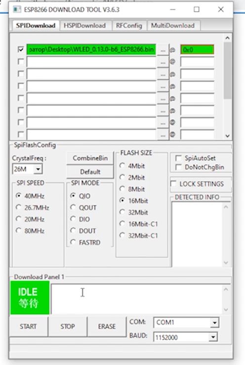
Тут в принципе все то-же самое за исключением адреса куда мы заливаем прошивку. Для ESP8266 адрес будет 0x0. А остальное по аналогии с ESP32.
После загрузки прошивки у Нас появится новая wi-fi сеть под названием WLED-AP.
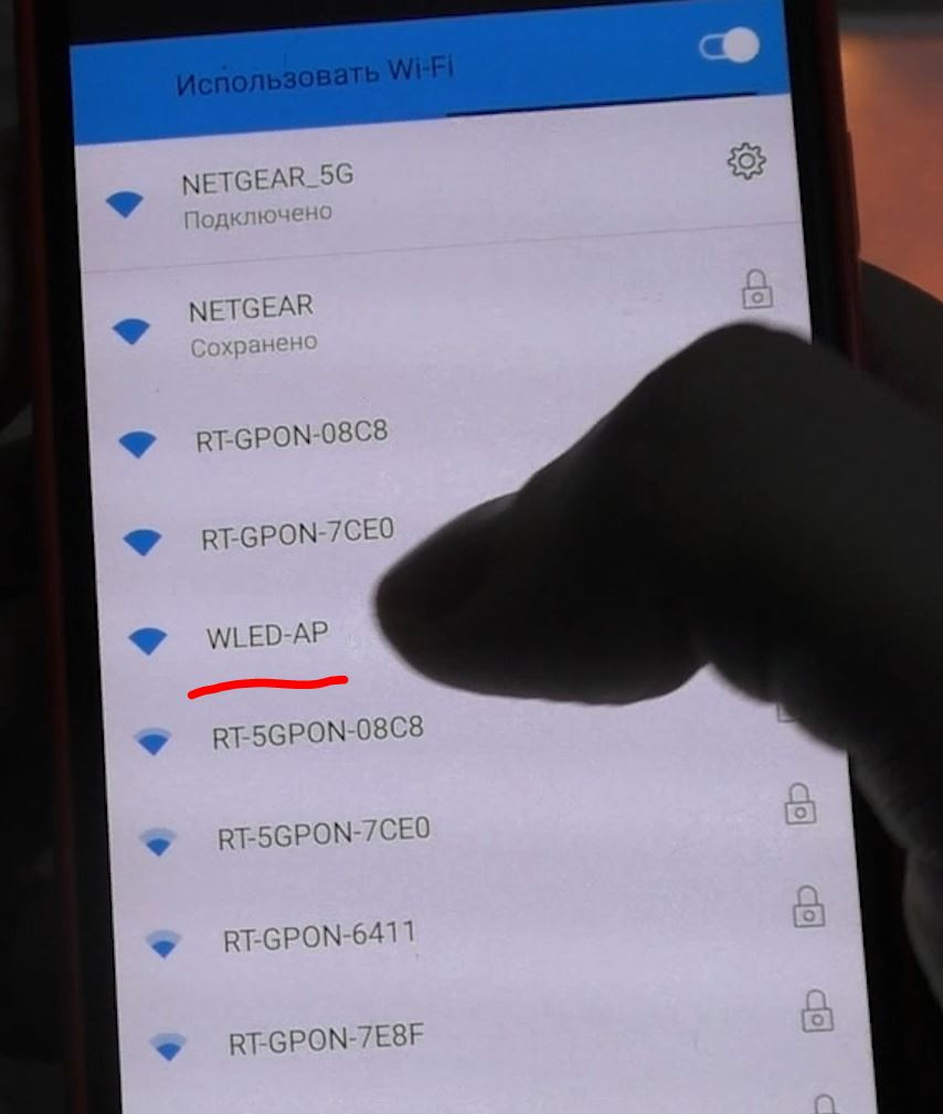
Пароль от нее wled1234
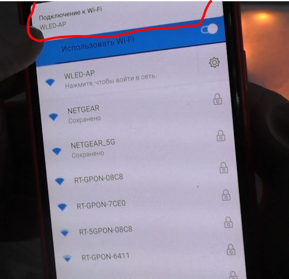
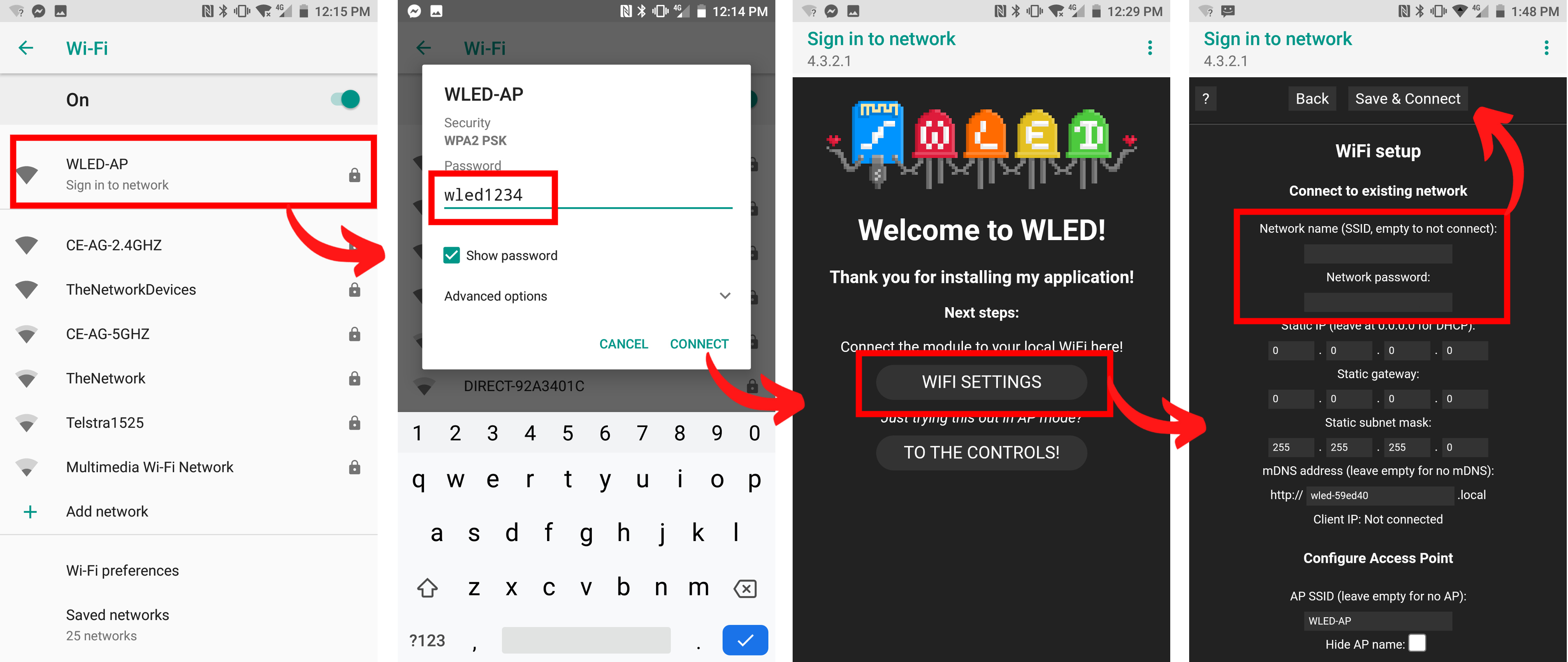
После того как приконнектетесь к этому wi-fi, выскочит окошко “Подключение к Wi-Fi WLED-AP” на которое нужно нажать и попадем на страничку настроек WLED
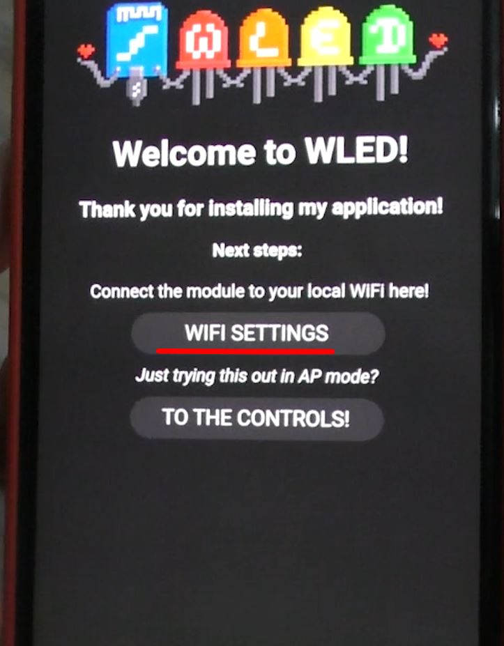
Где нажмем кнопку Wi-fi Settings:
Ну и в открывшемся окне нужно ввести SSID и пароль от Вашей существующей wi-fi сети. Для того, чтоб контроллер был в вашей локальной сети.
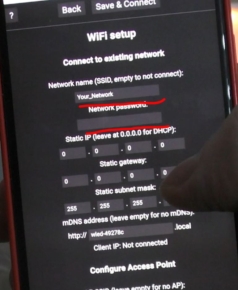
После этого сохраняем настройки и устройство скажет, чтоб мы подключились к нашей wi-fi сети которую мы указали в настройках. Подключаемся к ней.
Далее скачиваем приложение WLED. У меня андроид и в плей маркете есть данное приложение.
Скачиваем его и запускаем. После запуска у Нас откроется окно приложения и там не будет ни одного контроллера. ЧТоб добавить новый нажимаеп “Плюсик”
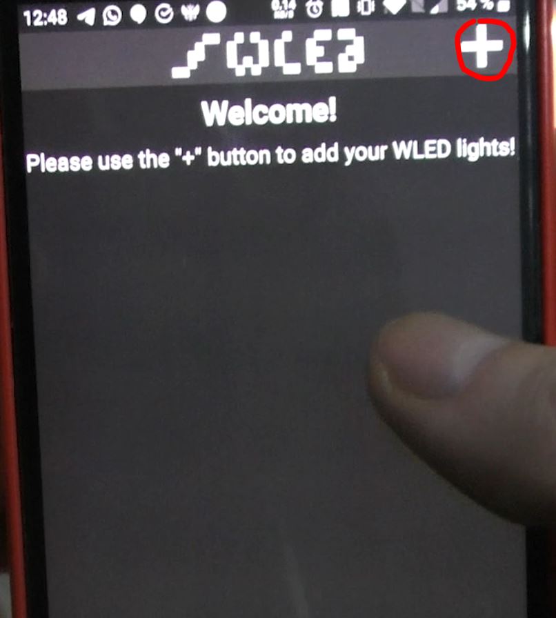
После этого откроется окно, в котором нам нужно нажать кнопку “DISCOVER LIGHTS…”
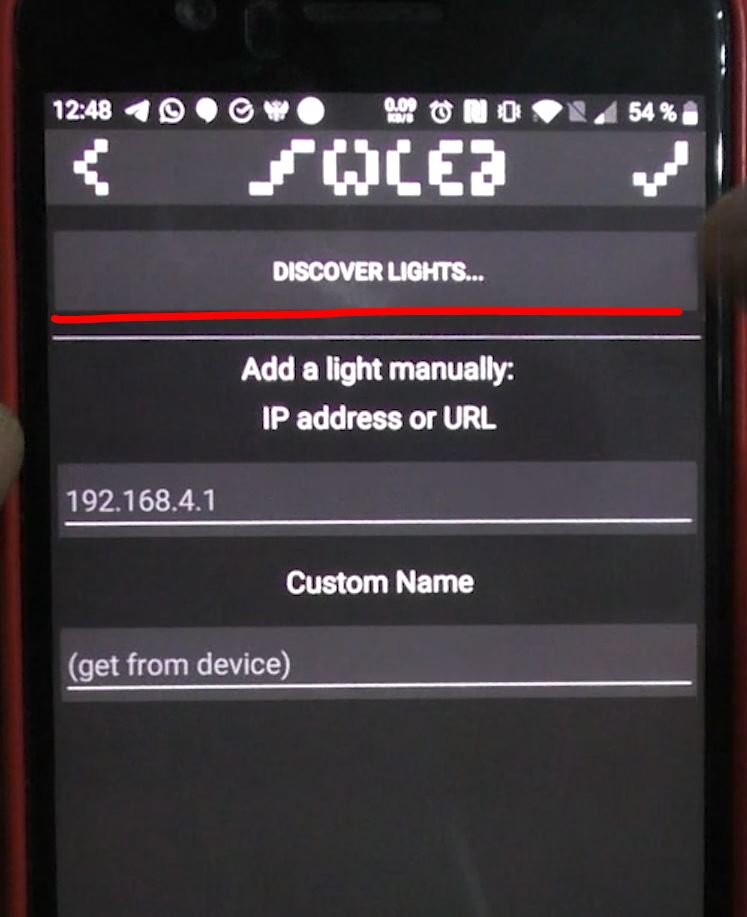
После этого вернуться назад и у нас уже будут добавлены все контроллеры WLED которые найдутся в этой сети.
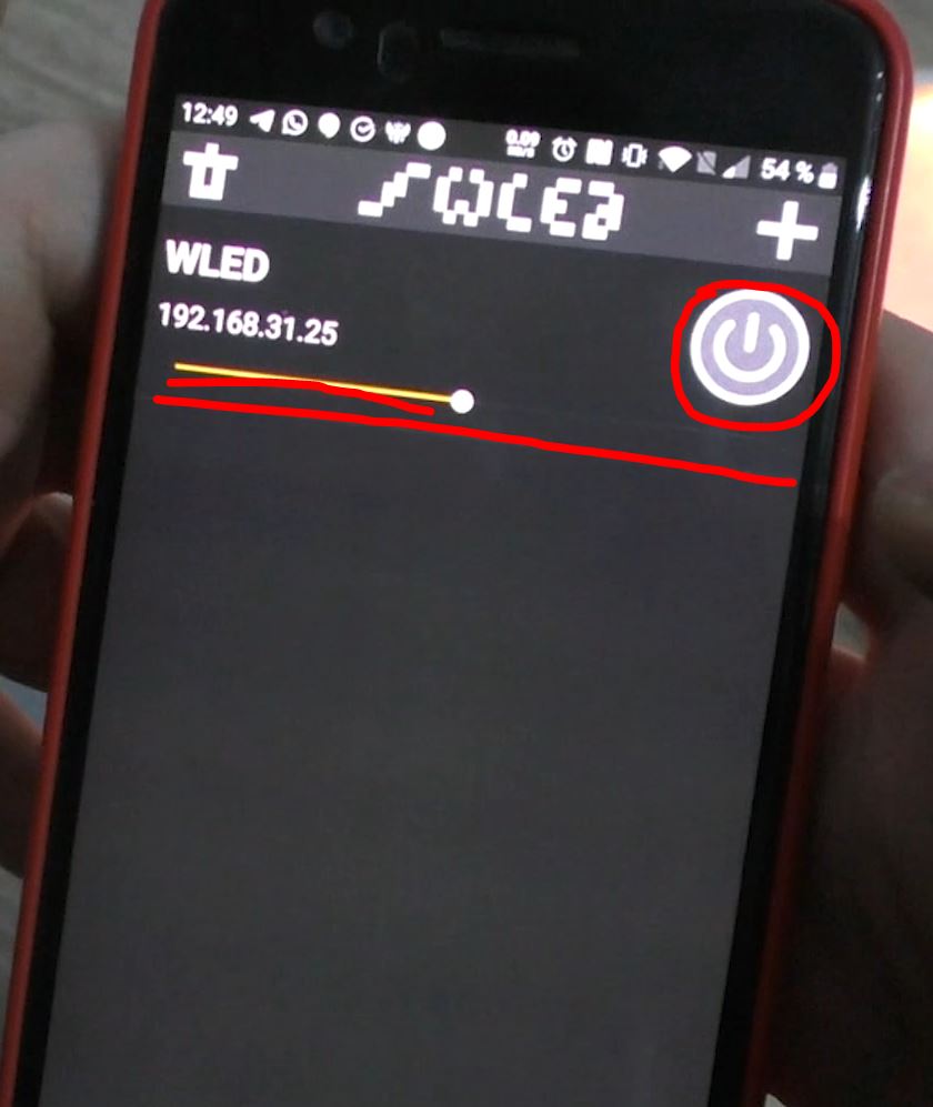
Отсюда уже можем управлять контроллером. А именно уменьшить или увеличить яркость свечения или выключить свечение вообще.
Если же нажмем на надпись WLED, то мы провалимся в основные настройки устройства.
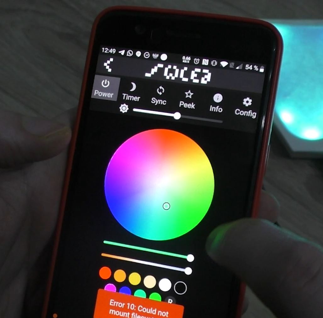
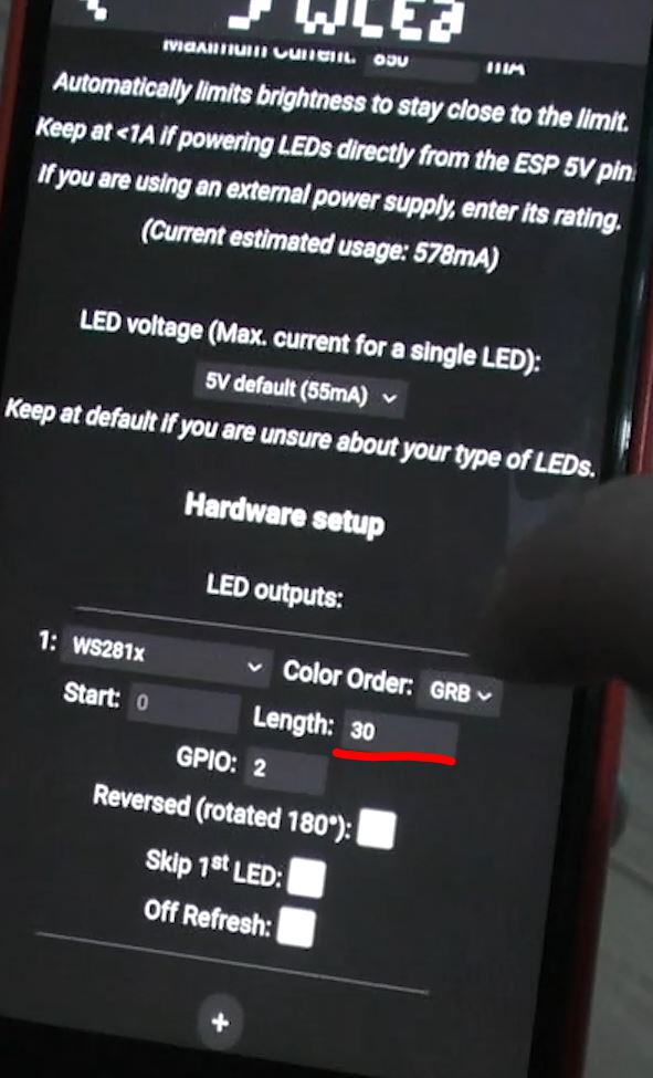
Тут миллион всяких палитр и эфектов. Про них не будем здесь. Я тут только покажу где поменять колличество светодиодов. Ведь в самом начале их всего 30.
Итак заходим в Config -> LED Preferences и там ищем графу “Length: ” И тут указываем Ваше количество светодиодов. И тут можно поменять GPIO к которому подключена лента.
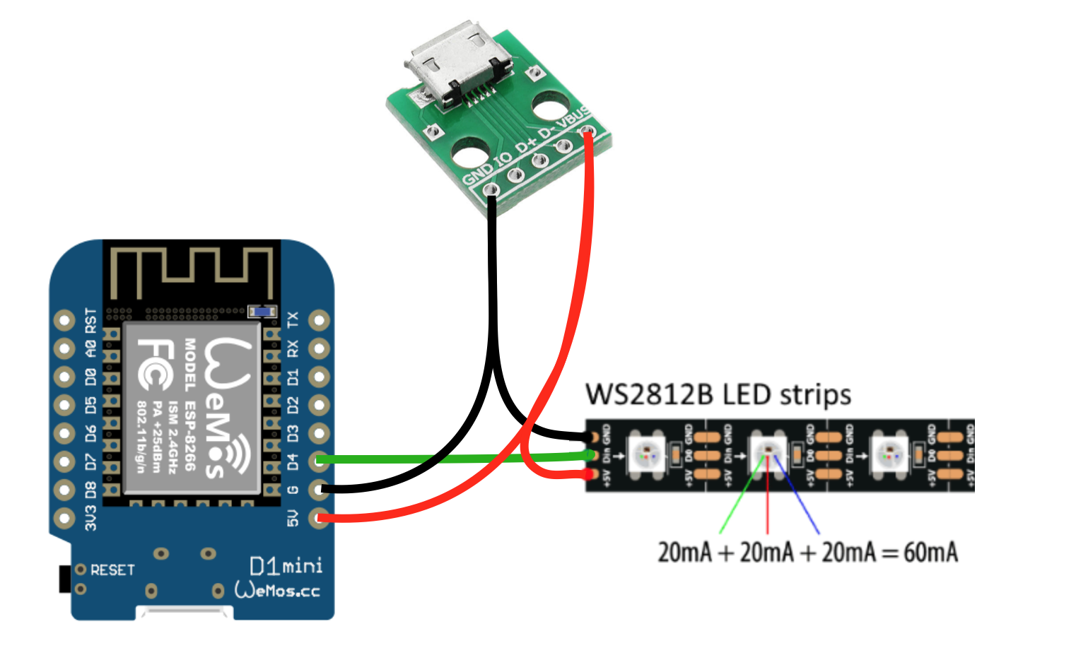
Ну а если кто не знает как подключить ленту WS2812 к ESP. То это выглядит примерно так:
Home Assitant.
Ну а теперь давайте про Home Assistant.
Ну тут все просто. Переходим на сервере Home Assitant в Настройки->Интеграции Там нажимаем “Добавить новую интеграцию” вбиваем WLED. Если у Вас контроллер в сети находится более 10 минут, то Home Assitant его найдет автоматически, если же нет, то вбейте туда ip адрес.
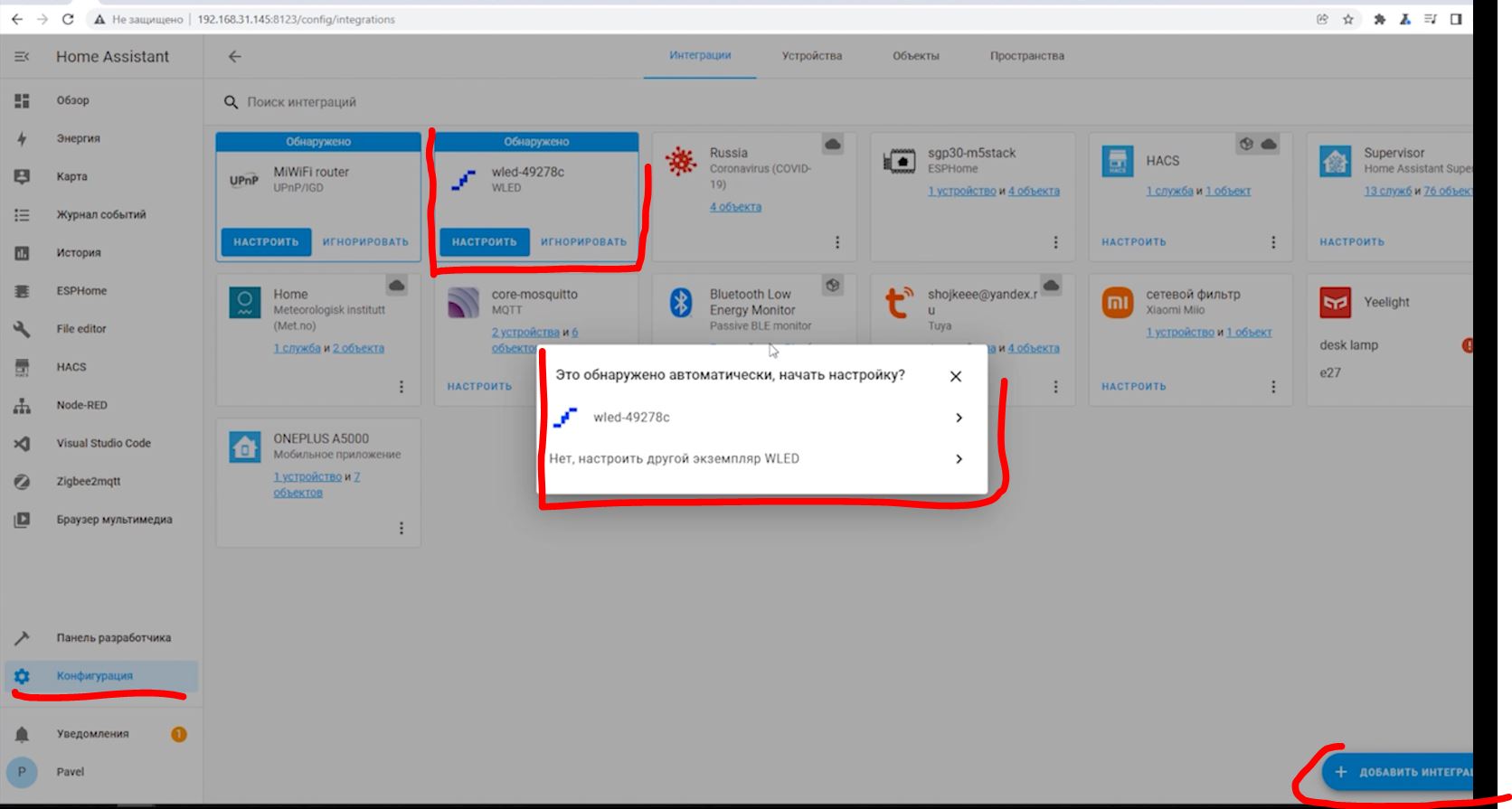
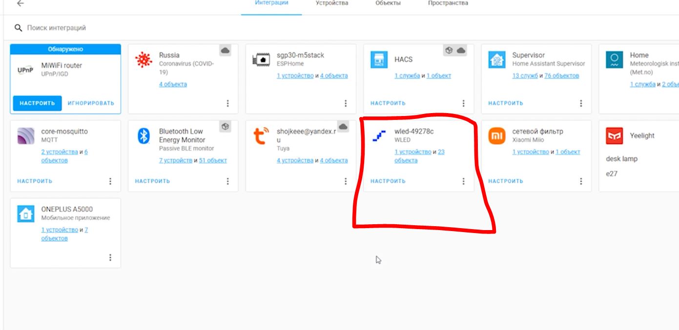
После добавления у нас в Home Assitant появится 1 устройство и 23 объекта. Все эти объекты мы сможем использовать в автоматизациях Home Assitant.
Ну а если хотите поуправлять контроллером так-же как и с мобильного приложения. То нажимайте здесь на устройство и откроется окно управления контроллером:

Ну и отсюда можем уже управлять так-же как и из приложения.
Getting Started
Welcome to the WLED wiki!
Unless noted otherwise, all information applies to the latest release (v0.13.3).
Quick start guide
1. Connect a WS2812B-compatible RGB(W) led strip to GPIO2 . On most ESP8266 based development boards this pin is labeled D4 , on ESP32 based boards use IO16 or G16 or 16 . If the connecting wire cannot be kept short, use a level shifter/translator. Optionally connect a normally open pushbutton to GPIO0 (NodeMCU/Wemos pin D3 , on ESP32 use IO17 ) and ground for configurable actions. Note: Board pin naming varies depending on the manufacturer. Please use the board pinout from the specific board you purchased and use the GPIO PINS to reference this guide. Make sure to connect ESP and LED-strip grounds together!

While using an ESP8266 and LEDs that have clock and data, you can either use hardware SPI (mostly faster) or software SPI. — hardware SPI: use GPIO14 (SCLK) for clock and GPIO13 (MOSI) for data. — software SPI: since all pins can be changed in the Hardware section of LED settings, you can use any pins. Recommend is to use GPIO1 (TxD) for clock and GPIO2 (D4) for data.
For safe operation it is recommended to size your power wires correctly and to integrate fuses.
For reference, you may use this LED power, wiring and fuse calculator.
For analog LEDs, the MOSFETs IRLZ44N or STP55NF06L are good candidates. Partial, example circuit.


2. Flash the software to your ESP module! There are two options for this step:
If everything worked the first thirty LEDs will light up in bright orange to stimulate courage, friendliness and success!
3. Use a WiFi device to connect to the access point WLED-AP using the default password wled1234 . You can also just scan this QR code:

Go to the IP 4.3.2.1 in your browser to control your lights! You should also be able to connect to wled.me if in access point mode (embedded DNS server).
Wifi Setup
To connect your WLED module to your home Wifi:
1. Click on the Config (gear) icon to edit your WLED module settings and choose ‘Wifi Setup’.
2. For most home networks, simply enter your Wifi network’s name and network password. You can also change the mDNS address for your WLED module here.
3. Click Save & Connect at the bottom of the page.
4. Reconnect your device to your home’s Wifi network.
5. Check the device list in your router’s user interface for the IP of the WLED device within your local network. For easy automatic discovery, use the WLED app! Have fun with the WLED software!
Default GPIO Usage
These are only defaults
All pins can be changed in the Hardware section of LED settings. Please note that these are GPIO numbers, please consult a pinout for your board to find the labeled pin (e.g D4 = GPIO2 on most ESP8266 boards). When using an ESP8266 board, it’s recommended to use pins GPIO1 , GPIO2 , or GPIO3 for LED Data; using other pins will require bit-banging and may cause slow performance and/or issues elsewhere (such as with IR decoding).
WLED Phone App | Control Addressable LEDs with an ESP32 or ESP8266
There are many ways to use your mobile phone to remotely control and manage ESP32 or even the older ESP8622 boards. Currently the best option, hands down, is WLED. A fully Open-Source phone application, WLED can be found for free in the Google Play Store or in the IOS App Store. So no matter your Phone type you can get in on the action. With the ESP32 board connected together, this application will allow you to control the LED lights exactly how you want. And you can control many, many ESP32 boards all from the singular application whilst also providing an expansive amount of easily adjustable built-in patterns.
Fully Addressable LED strips can produce whatever unique colour and brightness you want for each LED node. This provides an incredible amount of freedom. Creating a great Fully Addressable LED control system used to be complex, either having to start from scratch (coming up with light patterns and user interface) or taking the easier option and having to then use paid proprietary options (which have limited built-in patterns). This WLED application instead makes the whole experience much more user-friendly, elegant to navigate, and most importantly fun. This software is just too rad not to explore, so below are the contents of this guide.
Check out the image below of a Sparkfun ESP32 Thing Plus C set-up and powering 28 high-density RGB WS2812B LEDs. ESP32 and ESP8266 are perfect for use in this role, and both work exactly the same with WLED software. They are cheap and provide exactly what hardware you need and nothing more. The WLED software is really where the magic comes in. It provides heaps of pre-set patterns and custom LED styles. More options than I have seen elsewhere on paid software and much easier to create your own custom light using WLED.
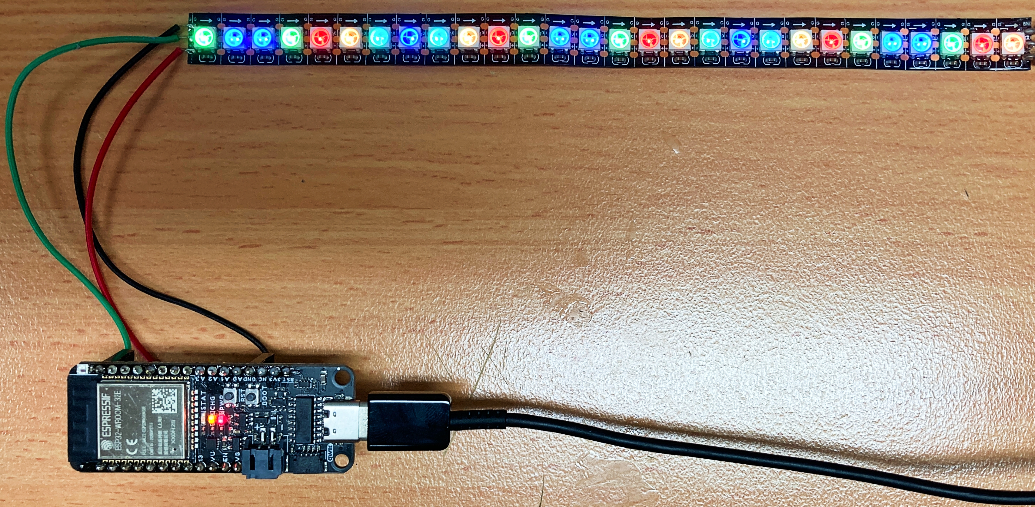
Now I have used Raspberry Pi full-sized computers to control fully addressable LED before (mainly because of previous lack of great software/knowledge to work with ESP32 Development Boards) but Raspberry Pis are so much more than a simple addressable LED control, they are full-on computers. So when it comes to a single addressable LED strip that you want to be good to go 24/7 but not necessarily be shining LED light everywhere all the time ESP32 are perfect for this application in regards to the much lower current draw (particularly when dormant), ease of power-cycling and significantly cheaper installation. Linked here is a great guide comparing the newer ESP32 to the ESP8266 board.
As always if you have any questions, queries, or things to add please let us know your thoughts!
Below is a list of everything you will need to get started with WLED. All the electronics here operate at 5V.
— ESP32 or ESP8266 Board. There are many types, for this guide I have used an ESP32 Thing Plus C. You could use a FireBeetle ESP32 IOT Microcontroller or any ESP32 or ESP8266 board that you wanted.
— Fully Addressable 5V LED Strip. There are many types, for this guide I have used a section of a 1M RGB LED Strip — WS2812B 144 Per Meter — Black Strip
Depending on how many LEDs you want to use you may want to have a secondary power supply for the LED strip so that it will have enough current available to the LEDs. Each RGB LED draws approximately 50mA when it is set to full brightness and powered at 5V. That means for every 30 LEDs that you have your LED strip could be drawing as much as 1.5 Amps.
As a first note, the max current you want to be pulling through an ESP32 Development Board Chip is
1200mA. Also for those curious, the max current out of a USB3.0 is 900mA. USB1.0 and USB2.0 deliver up to 500mA. That means, for peace of mind during testing, power the system via any USB as it will then not be possible to break the ESP32 by overloading it with the current. Also, if powering the system via a battery make sure that the C rating of the battery and the Amp capacity of the wire is high enough.
Note here as well, for ESP32-S2 and ESP32-S3, WLED App compatibility is close. With some tweaking of settings, you can create a functional system but is not quite there with all the features. ESP32-C3 board are currently not supported.
Setting Up WLED on an ESP32 Board
Turn on your desktop computer and open up your preferred internet browser (in my case Chrome). With that open, type and enter directly into the URL | install.wled.me |. The website this URL will take you to will look like the image below.

Connect your ESP32 Board to the Computer using any USB port. Download the correct one for your board (be it ESP32 or ESP8266). Make sure it has connected correctly and is in boot mode. You may need to install particular firmware for your device or drivers for your computer to have it pop up correctly in the COM Port list of devices. If you are running into issues here check the Troubleshooting section below. With that done click on the Install Button using the most up-to-date version and select the correct COM port. The installation process will then occur and should take less than 5 minutes, the image below shows the completed install.

As a Big note, WLED has made it even easier to provide WIFI details to the ESP32, these details can now be entered in as soon as you finish the installation process. See this option in the below image. If you do this you can skip past providing WIFI details section.

With that done unplug the USB and plug it back in to quickly reboot the ESP32 (which will now have the WLED software flashed to it). As a note, this is an ESP32 board and thus under normal operation, you can rip power from it at any time with absolutely no fear of damaging it.
The software we have flashed to it will run on boot. At this stage, we haven’t provided the ESP32 with any local WIFI details. So right now, your ESP32 is going to be running as a WIFI access point that we can connect to using any computer or phone (kind of like running headless with a Raspberry Pi, except easier to access).

At this point, I jumped onto my phone and searched for WIFI nearby, check the image below for a visual understanding of all the next steps.
Look for a network called | WLED-AP |. Join that and then type | wled1234 | when it requests a password. This will open up a | Sign in to network | page. You can also get to this page by opening up an internet browser (like Chrome) and typing the numbers | 4.3.2.1 | into the URL. Now on this page click on WIFI Settings. This will open up a new section called WIFI Setup. Here alter the Network Name and Network Password to be your internet network name and password. Now the ESP32 will be able to connect directly to our router instead of directly to our computer/phone. As a note, you can connect directly to the ESP32 and control lights without providing WIFI details but adding multiple ESP32 and creating an ecosystem of multiple LEDs all-around your house is much better managed by providing them all with WIFI credentials. Press | Save and Connect | and your ESP32 will reboot and then connect to your WIFI.
From here everything can now be done via the WLED App, make sure you have it installed on your phone if you haven’t already (you can also find it for free in the Google Play Store or in the IOS App Store).
Give your ESP32 a hard reset again by pulling power from it and plugging it back in. Reconnect your phone/computer to your desired WIFI. Having done this and after a couple of seconds, you should now be able to see WLED as a device that has connected to your internet system (all internet routers have some way of showing this). See in the image below, my phone, my computer (a Raspberry Pi), and my ESP32 Board are all connected to the same WIFI internet (sections in white have been hidden for security reasons).

You can now access your ESP32 device through your router using your Phone through the WLED App (or on your Computer using a Browser with the IP Address as the URL). Sweet!
From here on out we will be using the Android Version of the WLED APP but keep in mind that you could be using any computer or an IOS Phone (like the iPhone). When you first open up the WLED App it will look like the left of the image below. Click on the Plus symbol to open up the discovery page. Press Start discovery which will search through your WIFI for all boards running WLED software connected. Once it says | Found WLED! | like it says in the image below press the Tick button on the top right. This will bring you back to the home page where you will have a list of all the WLED Boards on your network. From here by clicking anywhere on the header you will be able to open up the phenomenal light settings section of this APP. This is where the magic really is.

Now if your ESP32 Board (or ESP8266 Board) has an onboard addressable LED used as a multi-status LED (like the Thing Plus C ESP32 WROOM board that I’m using here) you will be able to control it directly using this setup. You can see this in the image below, as I change the colour selected by pressing on the colour wheel it changes the multi-status LED to match.

Connecting Up ESP32 to Fully Addressable LEDs
So one LED is pretty Cool that must mean
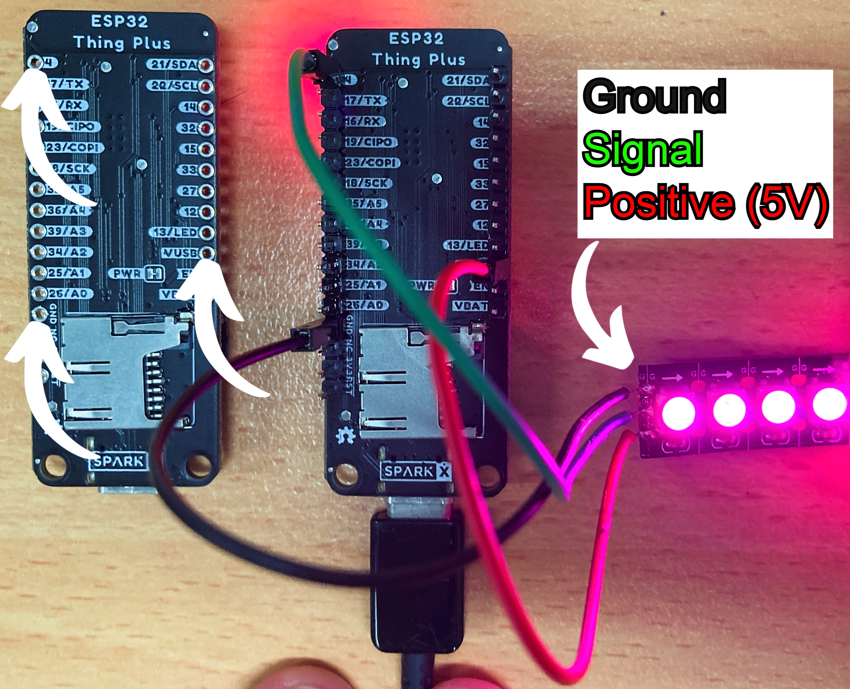
30 LED is 30 times cooler! There’s no Law of Diminishing Marginal Excitement at play here. To do this we must then connect the ESP32 to some Addressable LEDs just like in the schematic and image below. The black wire is ground, the red wire is 5V positive power and the green wire is the data wire, telling the lights what brightness and colour each should be. The easiest way to get this connection is by soldering headers to the board and adding Dupont connectors to the end of the strip.

Having done so and your LEDs are all wired up like the image below then you should be getting light through your system! Note that in the image below I have two ESP32 boards with one disconnected just to better show off the wire connection points.
Thus we can now choose certain colours from the colour wheel and baddaboom we have remotely activated fully operational addressable LEDs! Having achieved this we can get right onto exploring what is on offer with this WLED software!
LED Patterns and Menu Overview
Choosing custom LED light patterns is where the magic really is. See the image below for the main UI on the left and the Effects Menu on the right. Keep in mind the effect menu can be scrolled through for a long time. A particular favourite of mine is Fireworks.
So let’s have a quick look at this user interface. We have a simple | Power | button, this will turn the lights on or off (but not the ESP32 board). We have a | Timer | button, so we can organise the lights to come on and off at certain points during the day. We have a | Sync | button to update new LED patterns. We have a | Peek | button to test out custom-created light patterns. There is an | Info | button, providing details about the board and setup. There is also a | Config | menu which is talked about in the next troubleshooting section. Below this is a general brightness slider, the colour wheel including contrast and brightness tweak bars, and the ability to select multiple different colours (for use with the effects and segments).
Clicking on the | Effects | button will take you to a new deeper page (with an awesome and long list of effects) that can all have customisation done to, from speed, intensity, and colours. Clicking on the | Segments | button will also open a new deeper page allowing you to decide exactly what colours you want each portion of your LED strip to be.

Starting off simple we can select block colours for the WLEDs by pressing anywhere on the colour wheel. Personally, my recommendation to you at this point is just to explore the expansive options. This is the most fun part after all! Just check out the crazy custom colours that I created on my phone in less than 1 minute that appears to flow up the strip in the image below. This pattern would be much harder to code from first principles than it is just to use this brilliant WLED App.

Quick Troubleshooting and Tips
If you can locate your ESP32 or ESP8622 Board when you connect it to the computer or if it doesn’t pop up on one of the COM ports. Make sure that the firmware is fully updated for the particular board your using and that you connect the board to the computer in bootloader mode. To connect an ESP32 board in bootloader mode you may need to hold in the tactile boot button on the ESP32 board and then put power into the system by plugging it into the computer. There are a number of other potential methods to do this depending on the particular microcontroller used so refer to the datasheet of your particular board if running into strife. Also make sure you are using a cable (be it USB-C or USB-Micro etc) which has the ability to send data through it, not just power. Definitely try a couple of different connections cords as they are not all made equal, even if they look the same.
If your issue is that you have set it up like the images above and not getting any LED action. Double-check that you have allocated | Pin 4 | to be the pin to send out data to the fully addressable LEDs, you can find this in the | LED & Hardware Setup | menu easily found in the app. See the image below for a screen capture of what this setting menu looks like, make sure to scroll down to access this option.
If at the end of your strip some LEDs are not lighting up. Make sure the count of LED pixels matches the software. In the same | LED and Hardware setup | menu, you can directly tell the system how many LEDs you have hooked up. Adjust the value to the exact correct amount as this will make some effects look even better.
If the colours produced are inversed to desired. Make sure that the correct type of Colour Order for your Fully Addressable LED has been chosen. Common types are GRB, RGB, and BRG. This is found in the | LED and Hardware setup | menu.
You can also set up a current limiter in this | LED and Hardware setup | menu so you won’t ever ‘let the smoke out’ of your microcontroller. ESP32 Board likes to have less than 1300mA running through them. If more current is required to power a long LED strip then you will need to power the LEDs with a separate power supply. Make sure both systems share the same ground when running this kind of system. A LED driver board with standoffs to mount an ESP32 board directly to it would be a great way to simplify this.
WIFI works perfectly but I personally ran into some issues setting these devices up using my phone’s hotspot. I highly recommend using a WIFI from a router.

Have a question? Ask the Author of this guide today!