Virtualwire arduino 433 примеры
433MHz radio example
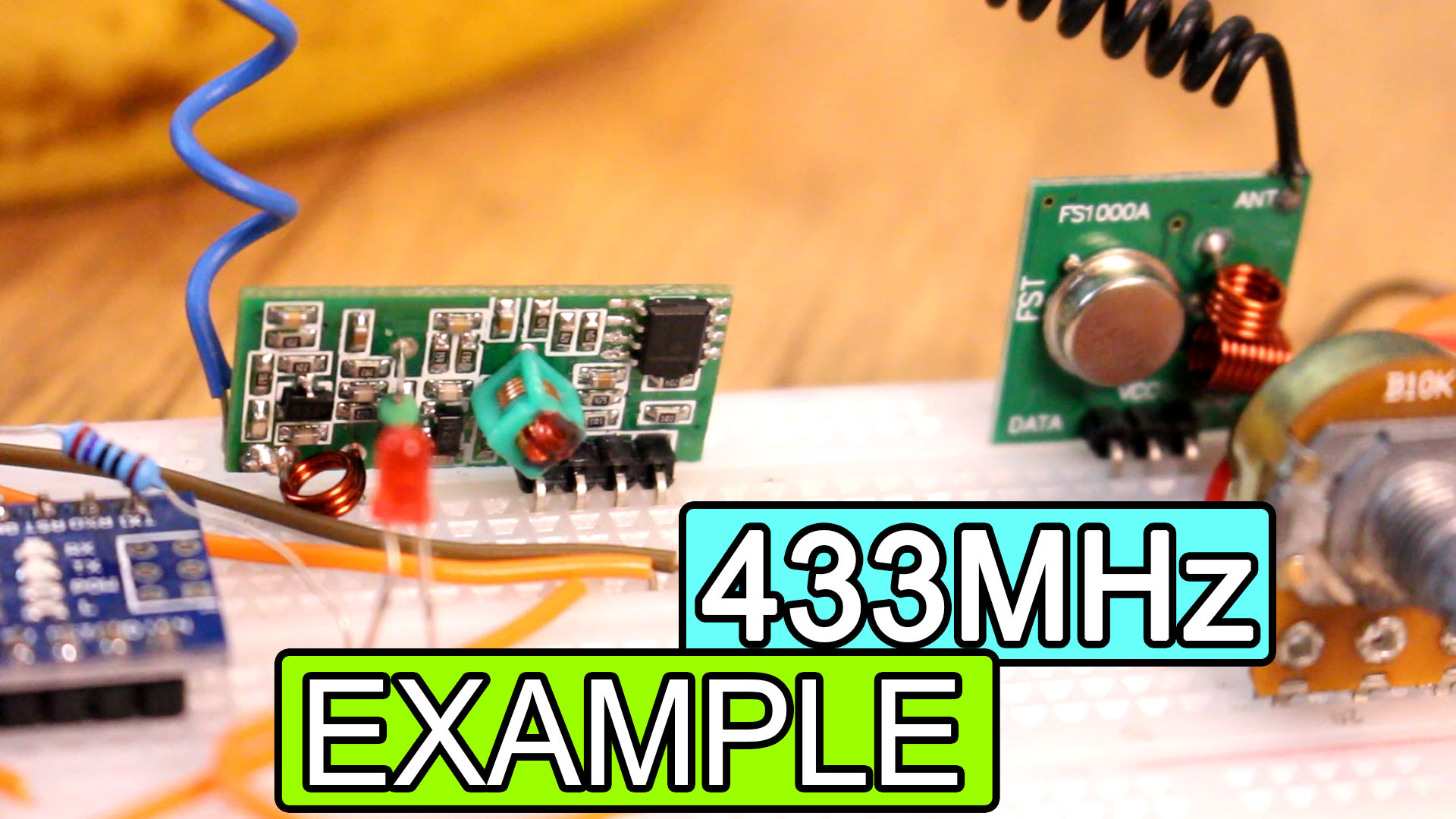
So, I’ve made a video with some radio modules you could use. In this case we will see the 433MHz radio module with virtualWire serial communication. See the connections below, download the example code and test if it works. You need two modules, rx and tx, an LED and a potentiometer and we will send just one byte of data, 0 to 255 values. The range for this module could be up to 100m.
PART 1 — 433MHz module
Ok, guys, now we have this very cheap module that works at 433Mhz or sometimes 315Mhz. The range depends on the voltage connected to the module and the antenna that we use. At 5V and with the stock antenna of the module, the range will hardly exceed 2 meters. Supply this at 12V and with a small copper antenna, the outdoor range can reach maybe 300 meters. Now the bad thing about these modules is that the communication is simplex (single and unidirectional channel) and they have low transmission speed (typically 2400bps). It basically works by ASK modulation (amplitude shift keying). They do not have a filter or hardware Identifier, so if we want robust communication, we will have to implement it by software.
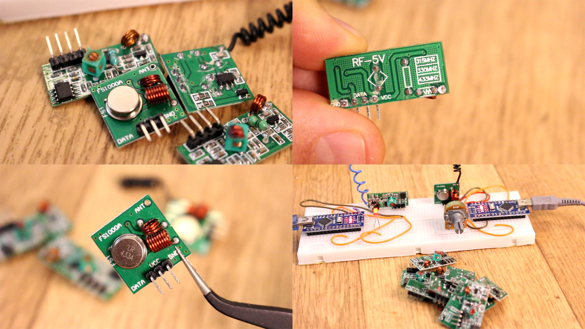
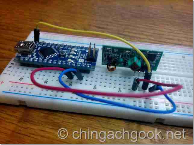
The connection is very simple. First, we power the modules by connecting VCC and GND, at 5V and GND from the Arduino. As we will see in the code, we will use the Virtual Wire library, which works with any digital pin. Therefore, we simply connect the DATA pins to any digital output as in the schematic.
PART 2 — Schematic
The schematic is simple but with a lot of pins. We have 2 Arduino NANO and we will use 5V from the Arduino in this case. If this doesn’t work, connect an external 5V to 12V supply and share ground. Anyway, connect the data pins and add a potentiometer, and LED and a resistor. Upload the codes below to the transmitter and receiver and read the comments in the code for more. Test if it works and you could change the brightness of the LED using the radio connection.

3.1 Transmitter
Here we have the transmitter code. You will need the virtuwalWire library for this module so download that from the code link below and install it to the Arduino IDE. Uplaod this code to the Arduino with the potentiometer. Read the comments in the code for more. Copy or download the code from below.
Arduino – передача данных по радиоканалу на частоте 433.920 МГц
GeekElectronics » Arduino от А до Я » Arduino – передача данных по радиоканалу на частоте 433.920 МГц
 В этой статье я постараюсь подробно описать процесс организации передачи данных между контролерами Arduino по радиоканалу с использованием передатчика MX-F01 и приемника MX-RM-5V.
Эти модули планирую использовать в своей умной метеостанции, чтобы избавиться от лишних проводов.
Для начала, давайте познакомимся с железом.
Технические характеристики передатчик MX-F01
- Напряжение питания: 3-12 В
- Ток потребления в режиме ожидания: 0 мА
- Ток потребления в режиме передачи: 20-28 мА
- Рабочая частота: 433.920 МГц (Есть на частоту 315 МГц)
- Выходная мощность передатчика: 40 мВт
- Дальность передачи: до 500 м в зоне прямой видимости с дополнительной антенной длинной 17,5, 35 или 70 см
- Тип модуляции: амплитудная
- Температурный диапазон: –10…+70 °C
- Размеры: 19х19х8 мм

Назначение выводов передатчика MX-F01

- ATAD — данные
- VCC — питание «+»
- GND — питание «-«
- ANT — антенна
Технические характеристики приемника MX-RM-5V
- Напряжение питания: 5 В
- Ток потребления: 4 мА
- Рабочая частота: 433.920 МГц (Есть на частоту 315 МГц)
- Размеры: 30х14х7 мм

Назначение выводов приемника MX-RM-5V

- GND — питание «-«
- DATA — данные
- VCC — питание «+»
- ANT — антенна
Базовую информацию получили – пора приступать к практической части.
Подключение передатчика MX-F01 к Arduino
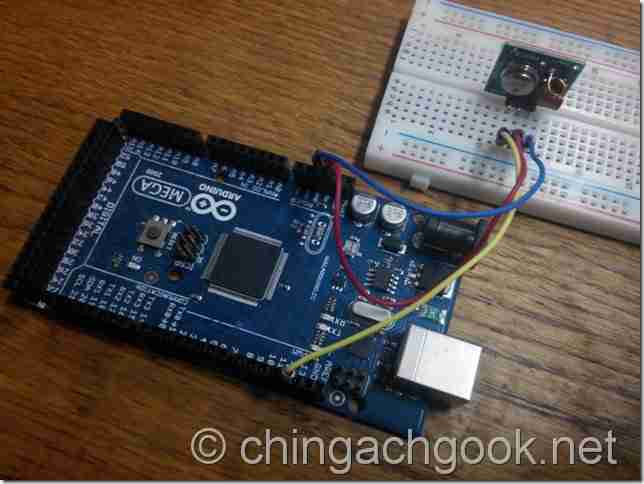
Для управления передатчиком MX-F01 я буду использовать Arduino Mega 2560.
Приступим к подключению:
- ATAD на MX-F01 подключаем к 12 дискретному выводу Arduino Mega 2560
- VCC на MX-F01 подключаем к +5V Arduino Mega 2560
- GND на MX-F01 подключаем к GND Arduino Mega 2560
- ANT на MX-F01 к антенне в виде куска провода длинной 17,5, 35 или 70 см (я пока антенну не припаивал)
Подключение приемника MX-RM-5V к Arduino
Для управления приемником я буду использовать Arduino Nano ATmega328.
- DATA на MX-RM-5V подключаем к 12 дискретному выводу Arduino Nano ATmega328
- VCC на MX-RM-5Vподключаем к +5V Arduino Nano ATmega328
- GND на MX-RM-5V подключаем к GND Arduino Nano ATmega328
- ANT на MX-RM-5V к антенне в виде куска провода длинной 17,5, 35 или 70 см (я пока антенну не припаивал)
Библиотека VirtualWire
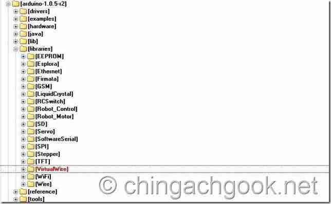
Чтобы упростить написания кода для работы с радиомодулями, была создана библиотека: VirtualWire.
VirtualWire.rar (17,3 KiB, 5 630 hits)
Распакуйте содержимое архива в папку /libraries/, которая находится в каталоге среды разработки Arduino.
Примеры кода для работы с передатчиком MX-F01 с использованием библиотеки VirtualWire
Пример 1
Данный скетч будет отправлять раз в секунду сообщение «Hello World». Для наглядности, в начале передачи будет загораться светодиод, а после окончания – гаснуть.
const int led_pin = 13; // Пин светодиода
const int transmit_pin = 12; // Пин подключения передатчика
void setup()
<
vw_set_tx_pin(transmit_pin);
vw_setup(2000); // Скорость передачи (Бит в секунду)
pinMode(led_pin, OUTPUT);
>
void loop()
<
const char *msg = «Hello World»; // Передаваемое сообщение
digitalWrite(led_pin, HIGH); // Зажигаем светодиод в начале передачи
vw_send((uint8_t *)msg, strlen(msg)); // Отправка сообщения
vw_wait_tx(); // Ожидаем окончания отправки сообщения
digitalWrite(led_pin, LOW); // Гасим светодиод в конце передачи
delay(1000); // Пауза 1 секунда
>
Пример 2
Данный скетч будет отправлять раз в секунду сообщение, которое содержит количество миллисекунд, прошедшее с момента начала выполнения текущей программы. Для наглядности, в начале передачи будет загораться светодиод, а после окончания – гаснуть.
const int led_pin = 13; // Пин светодиода
const int transmit_pin = 12; // Пин подключения передатчика
void setup()
<
vw_set_tx_pin(transmit_pin);
vw_setup(2000); // Скорость передачи (Бит в секунду)
pinMode(led_pin, OUTPUT);
>
void loop()
<
digitalWrite(led_pin, HIGH); // Зажигаем светодиод в начале передачи
String millisresult = String(millis()); // Присваиваем переменной значение, равное количеству миллисекунд с момента начала выполнения текущей программы
char msg[14];
millisresult.toCharArray(msg, 14);
vw_send((uint8_t *)msg, strlen(msg)); // Отправка сообщения
vw_wait_tx(); // Ожидаем окончания отправки сообщения
digitalWrite(led_pin, LOW); // Гасим светодиод в конце передачи
delay(1000); // Пауза 1 секунда
>
Пример кода для работы с приемником MX-RM-5V с использованием библиотеки VirtualWire
byte message[VW_MAX_MESSAGE_LEN]; // Буфер для хранения принимаемых данных
byte messageLength = VW_MAX_MESSAGE_LEN; // Размер сообщения
const int led_pin = 13; // Пин светодиода
const int receiver_pin = 12; // Пин подключения приемника
void setup()
<
Serial.begin(9600); // Скорость передачиданных
Serial.println(«MX-RM-5V is ready»);
vw_set_rx_pin(receiver_pin); // Пин подключения приемника
vw_setup(2000); // Скорость передачи данных (бит в секунду)
vw_rx_start(); // Активация применика
>
void loop()
<
if (vw_get_message(message, &messageLength)) // Если есть данные..
<
digitalWrite(led_pin, HIGH); // Зажигаем светодиод в начале приема пакета
for (int i = 0; i 
Для “Пример 2” кода передатчика

Не забудьте припаять антенны, а то без них дальность передачи будет всего несколько сантиметров.
На этом пока все.
Частота 433.920 МГц выделена для работы маломощных цифровых передатчиков таких как: радиобрелки автосигнализаций, брелки управления шлагбаумами на стоянках и другие подобные системы.
- Автор: source
- Миниатюра:
- Рубрика: Arduino от А до ЯArduino, MX-F01, MX-RM-5V, VirtualWire, передатчик, приемник —>
- Опубликовано: 05.02.2022
- Обновлено: 05.02.2022
- Комментариев: 7
- Просмотров: 72 592 searchПоисковые боты


Похожие записи
Комментариев: 7
Для “Пример 2” кода передатчика
у меня происходит странное явление. После увеличения разрядности счетчика (было 99ххх стало 100ххх) число полученных знаков остается старым (в нашем примере 5) и младший разряд не получается.
После перезагрузки приемника начинаем принимать 6 разрядов но при следующем увеличении разрядности история повторяется.
Хуже дело обстоит с перезагрузкой передатчика. Приемник принимает только 1 знак (думаю это связано с тем что время после включения =0 и первый раз передается только 1 знак)
Далее к передаче прибавляю текст и в начало и в конец. Получаю строку «HI 99123 LO». Проблема сохраняется — при увеличении длины переданной строки начинает резать последний символ.
Нашел ошибку
void loop()
<
if (vw_get_message(message, &messageLength)) // Если есть данные..
messageLength получает длину полученной строки. а в следующем цикле мы ее передаем как размер буфера (размер message) . в начале цикла надо заново инициализировать эту переменную
messageLength = VW_MAX_MESSAGE_LEN;
А можно как то без использования Arduino передать сигнал на приемник что бы при этом на приемнике светился светодиод?
К сожалению, без дополнительного контроллера не получится.
433 MHz radio modules using the VirtualWire library
Each of us met with incredibly inexpensive Ebay modules that allow wireless communication between Arduinos. The offer is incredibly varied and we look at the cheapest in this article. A dual transmitter and receiver that communicates at 433 MHz.
Purchase of parts
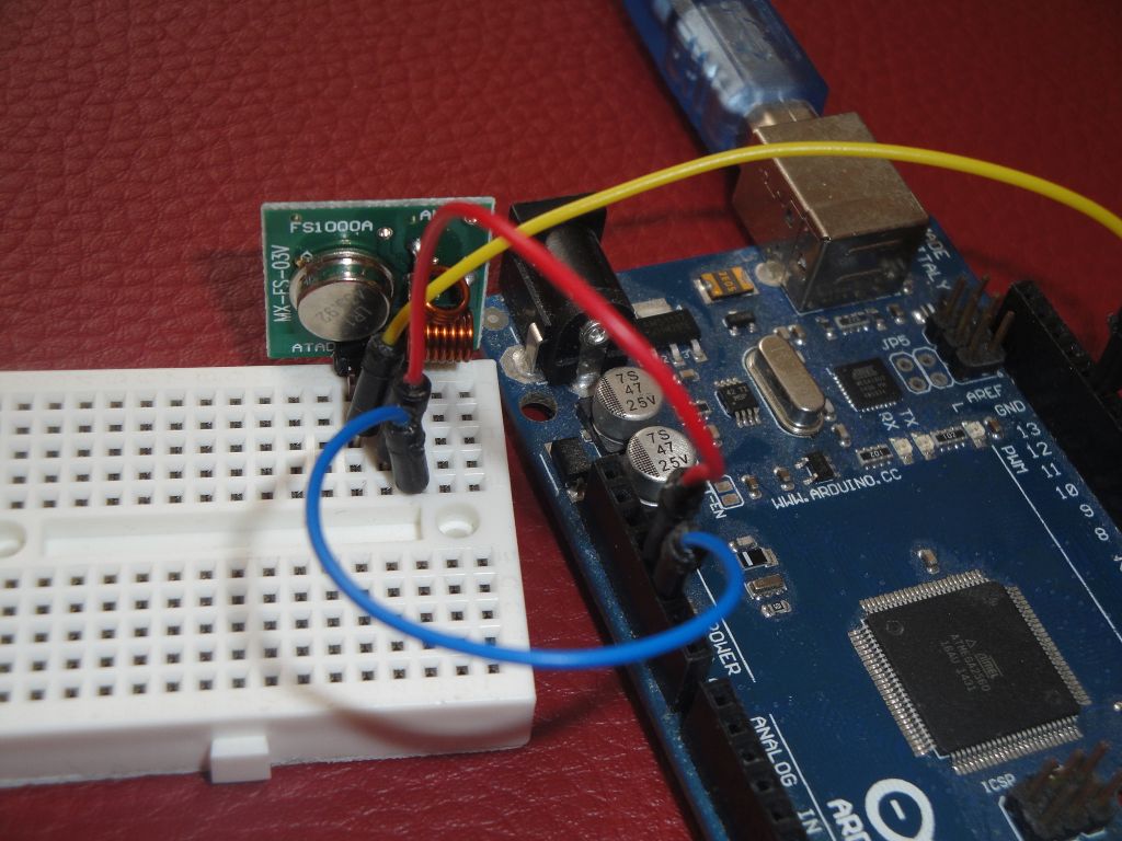
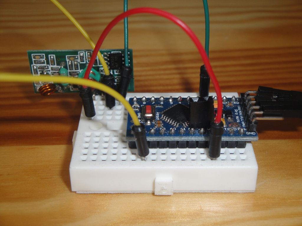
Arduino Pro Mini and Arduino Mega are used in the photos. It does not limit you, you can use any Arduino.
- Arduino Pro Mini (link) — I used this Arduino as a receiver.
- Arduino Mega (link) — I used this Arduino as a transmitter.
- Mini Breadboard (link) — I plugged the radio modules into this breadboard.
- Radio modules (link) — 433 MHz radio modules are usually sold in pairs. Although they have different designations, they seem to be virtually identical. They have the following names: XD-RF-5V, MX-JS-05V, XD-FST, MX-FS-03v, XY-MK-5V, FS1000A. Radio modules are sold without an antenna. This has a great impact on the broadcast range. If you want to transmit even more meters, you must attach the antenna to both modules.
Antenna length
Here the data differs slightly on the Internet, but it is usually 17.5 cm (alternatively 15 cm). This length must not be strictly observed in amateur conditions. Basically, every piece of wire you attach will significantly improve the properties of the transmitter.
VirtualWire
You do not find this library in your library manager and you need to install it from a zip file. The library home page is http://www.airspayce.com/mikem/arduino/VirtualWire/index.html. The author writes that the library is no longer developing and has been replaced by the RadioHead library. This is a library from the same author and we look at it in the next article. This does not bother us and install it in the [username]\documents\arduino\libraries\virtualwire directory.
Program (sketch)
These two simple programs communicate together. The first sends incrementing numbers to easily check connection failures, and the second program receives these numbers and displays them on the serial port. You see in the statement how many characters were received and what is the difference with the previous message. If there is a difference of 1, then there was no outage. If the number is bigger, then so many messages have gone out. Then it’s easy to manipulate both Arduinos and watch what happened.
With an attached antenna, the modules were able to communicate at a distance of 6 meters, with minor obstructions in the form of doors. A greater distance and through a concrete wall has been communication more difficult.
Transmitter
The data pin is connected to pin 12 in Arduino. If this does not suit you, you can change it with function vw_set_tx_pin .
Receiver
The data pin is connected to pin 11 in Arduine. If this does not suit you, you can change it with function vw_set_rx_pin .
Source code
The source code is located on the GitHub server.