Arduino и реле
Описание
Электромагнитное реле – универсальный способ коммутировать нагрузку. Универсальность в том, что реле имеет чисто механический контакт, то есть физически замыкает контакты. Это позволяет коммутировать нагрузку как переменного, так и постоянного тока в широком диапазоне напряжений: от 0 до сетевого, то есть 220 Вольт. По току производитель обещает 10 А, то есть можно коммутировать например 2 кВт обогреватель. Само реле напрямую к микроконтроллеру подключать нельзя, поэтому для управления силовая схема развязывается с логической, соответственно китайцы выпускают несколько типов модулей реле:
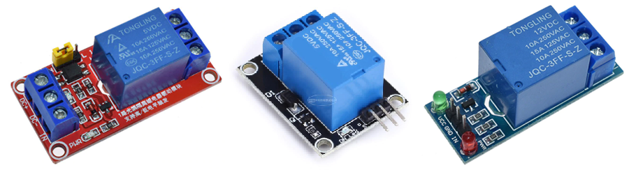
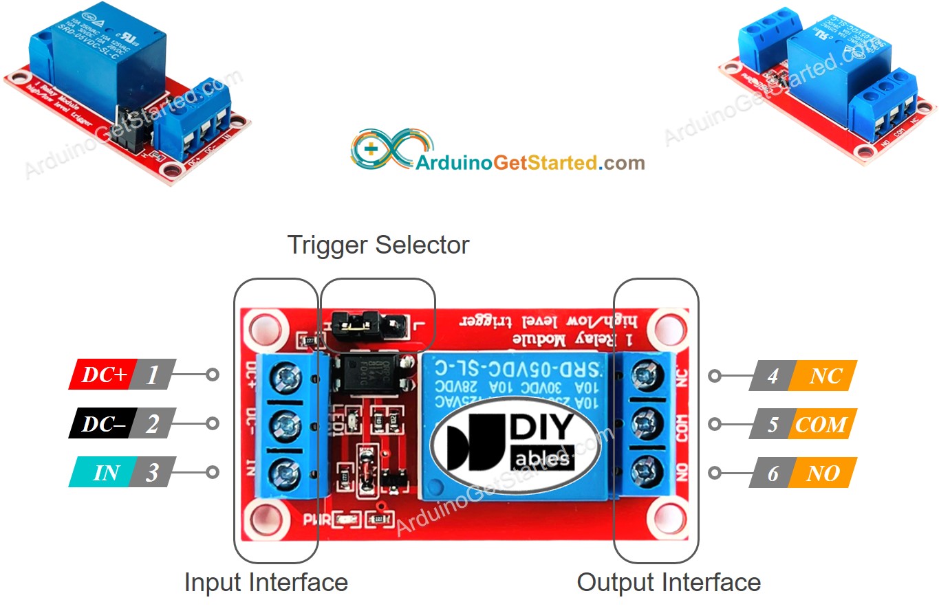
В наборе идёт красный модуль с настройкой логического уровня (жёлтый джампер-перемычка между буквами H и L). В центре – самый дешёвый модуль с минимальной обвязкой, высокого уровня. И справа – тоже неплохой модуль, но низкого уровня, что не всегда удобно использовать. Примечание: реле высокого уровня переключается при высоком сигнале на логический вход, а низкого – низком. Все модули реле имеют три пина на одном конце и три на другом:
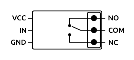
Слева находятся пины питания и управления самого реле:
- VCC (DC+, +) – питание
- GND (DC-, -) – “земля”
- IN (S) – логический управляющий сигнал
Справа находятся выходы самого реле, это одна контактная группа с переключением:
- COM (Common) – общий контакт
- NO (Normal Open) – нормально разомкнутый относительно COM контакт
- NC (Normal Close) – нормально замкнутый относительно COM контакт
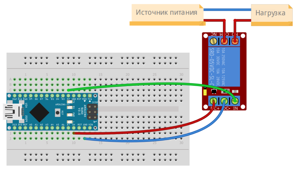
Работает это следующим образом: само реле (синяя коробочка на плате) питается от VCC и GND и подключается на питание схемы, так как реле потребляет около 60 мА при переключении. Но управляется реле логическим сигналом от микроконтроллера, который подаётся на пин IN. На выходе реле наблюдается следующая картина: у неактивного реле замкнуты контакты COM и NC. При активации реле контакт переключается и COM замыкается с NO.
Реле высокого уровня будет включаться и потреблять ток при подаче высокого сигнала (5, 3.3V), а низкого – при подаче низкого (GND, 0V). Чисто логически удобнее использовать реле высокого уровня: подали высокий сигнал – реле включилось. Мы кстати разбирали реле вот в этом уроке. И вот в этом:
Подключение
Примеры
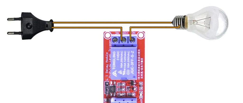
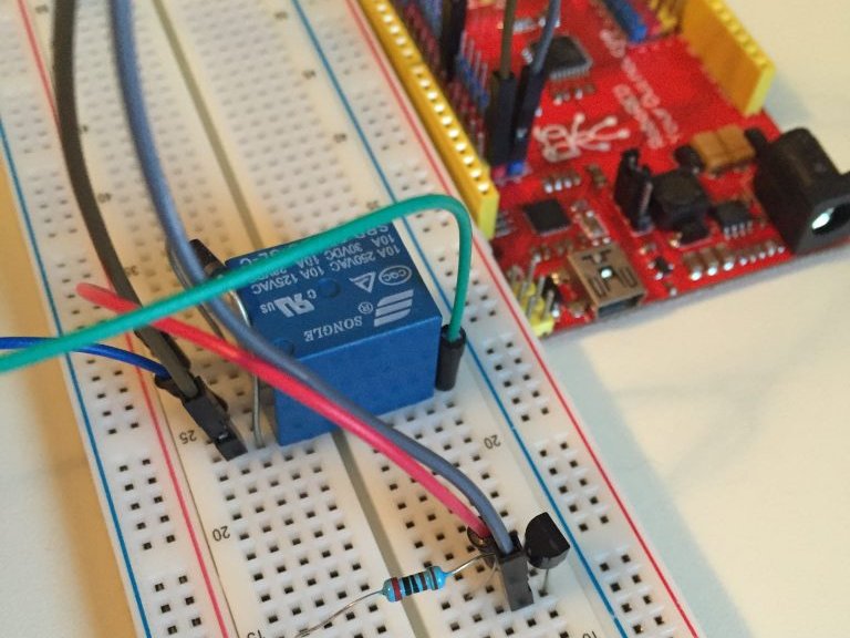
Для активации реле достаточно подать высокий сигнал (для реле из набора) на логический вход. Для примера и проверки подойдёт и классический пример “мигания светодиодом”:
How To Use A Relay With Arduino © GPL3+
In this project I am going to guide you through connecting a relay with arduino and as an example blinking a bulb.
gather all the parts needed for build
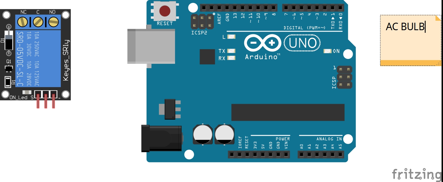
Step 2 Assemble:
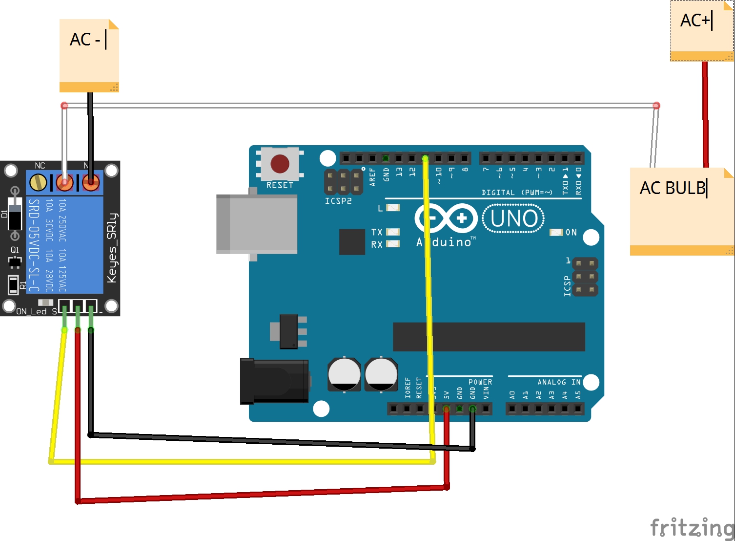
connect evrything like this-
Step 3 Upload the code:
upload the code.
CodeArduino
schematics
Please log in or sign up to comment.
Author

muhammed shameel k.v
- 7 projects
- 8 followers
Published on
Members who respect this project
Table of contents
Similar projects you might like
This is my 4th tutorial on how to drive a RELAY (not a relay module) with an Arduino.
Driving A Relay With An Arduino
![]()
As the title says, this is a pretty simple PIR motion controlled relay using an Arduino Nano.
PIR Motion Controlled Relay Using Arduino Nano!
Project tutorial by HeathenHacks
![]()
A Proper HOME AUTOMATION BOARD with 5V 2A Power supply and SMT BT Module
Simple Home Automation with Bluetooth and Relay
The Arduino Bluetooth Relay 12 Channels App supports control of a 12 channel relay module via Bluetooth (HC-05, HC-06, HC-07 ect.) modules.
Arduino – Bluetooth 12 Channel Relay App
Why use a relay module when plain relays are cheaper? We will show you how to control your lights with an Arduino.
Control Your Lights With Arduino And A Relay
2 wire 8 channel Relay Module || Reduce your CPU workload by interface 74LS164N.
Nano Relay Module
Project showcase by Boaz Lawnce
Good to see you again
Or connect with your social account:
Arduino — Relay
In a previous tutorial, we have learned how to turn on/off an LED. In this tutorial, we are going to learn how to turn on/off some kind of devices that use the high voltage power supply(such as a light bulb, fan, electromagnetic lock, linear actuator. ).
The common: Just like controlling LED, we use the Arduino’s output pin to turn on/off them.
Hardware Required
| 1 | × | Arduino UNO or Genuino UNO |
| 1 | × | USB 2.0 cable type A/B |
| 1 | × | Relay |
| 1 | × | LED Strip |
| 1 | × | 12V Power Adapter |
| 1 | × | Breadboard |
| n | × | Jumper Wires |
About Relay
A relay is a programmable electrical switch, which can be controlled by Arduino or any micro-controller. It is used to programmatically control on/off the devices, which use the high voltage and/or high current.
It is a bridge between Arduino and high voltage devices.
When you are making projects that are connected to mains voltage, you need to know what you are doing, otherwise, you may shock yourself. This is a serious topic, and we want you to be safe. If you’re NOT 100% sure what you are doing, do yourself a favor and don’t touch anything. Ask someone who knows!
Although some kinds of relays support both DC and AC devices, We highly recommend you to use a DC device (≤24V) for testing.
Relay Pinout
Relay has two groups of pins: input (low voltage) group and output (high voltage) group.
Controlling Relays with MKR Relay Shield
AUTHOR: Karl Söderby
LAST REVISION: 10/05/2022, 01:00 PM
Introduction
In this tutorial, we will test out the relays onboard the MKR Relay Shield. This shield is a great addon for any MKR Family board, as it has two 24V relays and additional space for soldering on components, hence the name «proto», as in prototype.
The sketch for this tutorial is really simple. It will activate one of the relays with a corresponding LED while de-activating the other, and then continue to do so every second, much like the standard blink example but with relays!
Note: The LEDs in this tutorial are optional. They do not serve any other function than signalling the state of each relay on the shield.
Goals
The goals of this project are:
- Understand how relays work, and what they can be used for.
- Activating both relays on the shield.
- Turn ON or OFF an LED to indicate the state of a relay (optional).
Hardware & Software Needed
- Arduino IDE (online or offline).
- MKR Relay Shield (link to store).
- Arduino MKR family board (link to store).
- 2x generic LEDs (optional).
- Jumper wires (optional).
- Breadboard (optional).
Relays
Relays allow low-power microcontrollers, to handle circuits that use much higher power than what the board can handle directly. They are typically used in industrial applications to control high power circuits, but they are also used in cars, homes and other electronic applications.
Relays are composed by an electromagnet that moves a tiny metallic plank, which is called COM terminal, between two different positions. That is, the NC terminal and NO terminal. We can decide in which position the COM terminal is connected to through activating/deactivating the electromagnet and by connecting a low power signal in the electromagnet control terminals.
Writing a program to control the relays is simple: it works very similar to turning an LED ON or OFF. Take a look at the snippet below to understand how it is used:
And that’s basically how we control the relays. Depending on the configuration, the logic will be inverted. For example, if we are using an NC (normally closed) configuration, we need to write a LOW signal to activate the relay. If we are using an NO (normally open) configuration, we need to write a HIGH signal to activate the relay.
The MKR Relay Shield
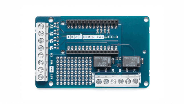 The MKR Relay Shield.
Inside the MKR Relay Shield, the low power circuit is already made. The only thing we need to connect is a power supply (max 24V), and a high power component (max 24V). These are connected to the high power pins. In the image below, you can get a better understanding on the different features of the MKR Relay Shield:
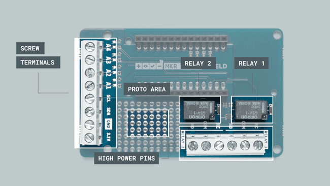 Different features of the board.
Circuit
Let’s begin by mounting our MKR family board on top of the MKR Relay Shield.
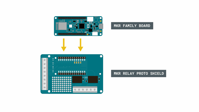 Mounting a board onto the shield.
Optional: We can then assemble the circuit for the LEDs, using a breadboard, resistors and jumper wires.
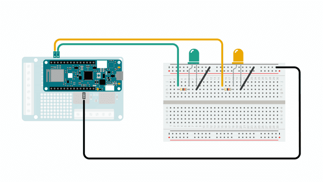 Creating a status LED circuit for the relays (optional).
Programming the Board
We will now get to the programming part of this tutorial.
1. First, let’s make sure we have the drivers installed for the board we are using. If we are using the Web Editor, we do not need to install anything. If we are using an offline editor, we need to install it manually. This can be done by navigating to Tools > Board > Board Manager. . Here we need to look for the Arduino SAMD boards (32-bits ARM Cortex M0+) and install it.
2. Now, let’s take a look at how we will activate our relays. We are actually not using a library, as the operation is very basic.
- — assigns to pin 1. It is important that we assign it to pin 1, as the relay is internally wired to this pin.
- — assigns to pin 2. Same here, the relay is wired to pin 2, so we can’t use a pin of our choosing.
- — configures relay 1 to be an .
- — configures relay 2 to be an .
- — write either a high or low state to relay 1.
- — write either a high or low state to relay 2.
The full code for the sketch can be found in the snippet below. Upload the sketch to the board.
Testing It Out
After we have uploaded the code, the program will start running immediately. If everything is working correctly, we will hear a «tick-tack» noise, and see the two LED’s go ON and OFF. This is the noise coming from the relays switching ON and OFF. We have now achieved a simple ON / OFF sequence every one second.
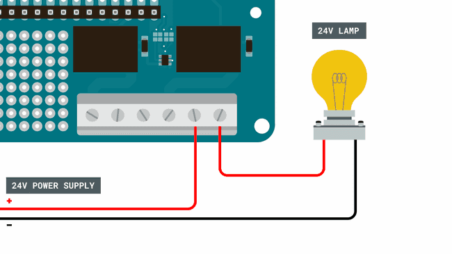
Now in this example, we have simply activated the relays, but we still haven’t connected anything to them. While we are not going to go in-depth on how to connect high power components, we can take a look at how a circuit looks like for turning ON or OFF a 24V lamp.
Let’s begin with the high power pins on the MKR Relay Shield. There are six in total for both relays, where there are three different type of connections: NO, COM and NC.
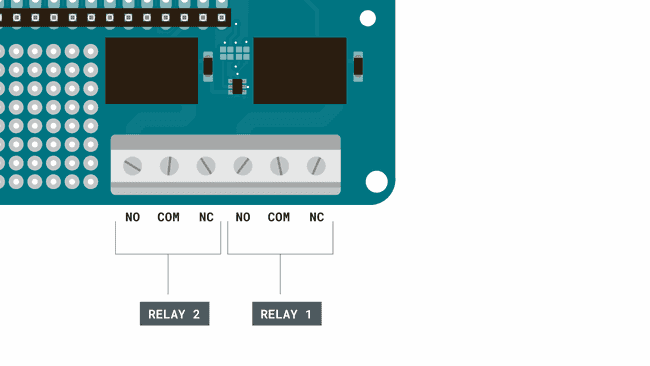 High power pins.
In this scenario, we are going to use the NC configuration, which means that writing a LOW signal to the relay will connect the NC pin to COM, which provides power to the connected component. The circuit could look something like this:
 Connecting high power component.
In this circuit, we are using a 24V power supply and a 24V light bulb. Now, if we were to write a program for this we would activate through using:
and to de-activate it:
Note: Use extreme caution when creating higher power circuits. Make sure that both the power supply and the component does not exceed 24V. For example, connecting it straight to a wall socket without a power converter would supply 220-240V, which is 10 times as high.
Troubleshoot
If the code is not working, there are some common issues we can troubleshoot:
- We have not connected the LEDs properly (this is an optional requirement).
- If the code fails to compile, make sure there’s no missing curly brackets or semicolons anywhere in the code.
- We have not connected the MKR board correctly on top of the MKR Relay Shield (the pins should match each other).
Conclusion
In this tutorial, we have gone through the basics of how a relay works, including how the internal mechanism works and how to create a circuit with high power components. Lastly, we learned how to create a program that activates or de-activates them.
Relays are incredible popular electronic components that are practically used everywhere: cars, planes, heating systems, industrial machines and many many more.