Tutorial: An SD card over SPI using STM32CubeIDE and FatFS
Let’s have some fun with files
Embedded projects often call for some kind of data storage and retrieval. For instance, you might have need for a data logger to record data points over long periods of time. You might have user settings that need to be preserved after the device is shut off and rebooted. You might want to profile your application, or debug certain features.
There are a number of ways to do this, and one of my favourites is to add an SD (or other memory) card to a project. It’s not too complicated, and it adds a lot of flexibility, as you can easily take the SD card out of the project and examine it with another machine. My second favourite method is to slap on a 20 cent EEPROM, but while that’s cheaper it’s a lot less flexible and usually stores a lot less data!
I’ve been asked more than once if I have any good tutorial resources for adding SD cards to an embedded project. Well, there are a few good tutorials and resources floating around online (including even my own resource from 2017) but some of them are a bit dated, relying on older tools and libraries. Further, while there are some amazing resources (e.g. ChaN’s) on talking to SD cards over SPI, there are less that describe how to interface this with file systems such as FAT, and less again that describe how to do it while also working with STM32’s build environments. Complicating matters is that officially you should use the STM32 SDIO peripheral to interface with an SD card — however, not all STM32s have the SDIO peripheral, leaving us to fall back on the SPI method (That said, it is worth noting that not all SD cards support the SPI interface).
Well, in this tutorial I’m going to walk through the steps that one would use to get an SD card working over the SPI interface on a STM32 dev board (re-)using my FatFS driver from 2017. FatFS is an amazing open source project also provided by ChaN which has since been integrated into the STM32Cube tools. If you’re interfacing with an SD card using the SDIO peripheral, it’s pretty easy and the tooling does most of it for you. If you’re working with other kinds of configurations, e.g. SD card over SPI, it’s actually still pretty easy — you just need the appropriate driver! So, today I want to show how you can use the FatFS libraries within the STM32CubeIDE development environment, and show how you can simply drop in the appropriate SPI driver to make everything work.
I’ll be assuming that you already know the basics of creating a project and setting up debugging and so on. If not, then please check out this earlier tutorial, in which I walk through getting started with STM32CubeIDE.
TL;DR: CubeIDE with FatFS. The complete code project is available here.
Equipment for this tutorial
Today I will be using the following:
- (Free) Ubuntu Linux 20.04 because developing on Linux makes me happy and Ubuntu makes it easy. Don’t worry if you’re on Windows, you should be able to follow along with roughly the same steps.
- (Free) STM32CubeIDE
- ($19.95 from Amazon Prime, $15.05 from Amazon) The Nucleo-F303RE development board.
- ($5 from Amazon Prime) An SD card breakout board (comes in a pack of two).
- ($6 from Amazon Prime) Easy-to-use ribbon cables (there’s more than you need here but they’re handy to have around).
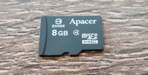
- A micro SD card — note that not all SD cards will work in SPI mode. I have an Apacer one that works, and a Kingston one that does not. YMMV.
Note: The above Amazon links are affiliate links. As always I encourage you to shop around, but Amazon usually has pretty good pricing.
The software stack
In this blog post I’m not terribly interested in the low-level behaviour we’re using to get an SD card working beyond “we talk to it over SPI”. It’s worth knowing though, so go check out what ChaN wrote, and then come back. The key knowledge that I want to show in this tutorial is around the architecture of an embedded application that wants to use an SD card with a FAT file system (using the FatFS library).
In general it’s always useful to visualise the architecture of what you are working with. In a FatFS system it looks like this:
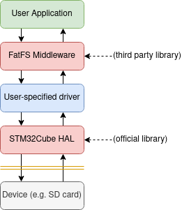
FatFS is provided as a Middleware which can translate FAT file structures in memory into their actual files. Handy! For it to do its magic, it needs access to a storage medium. It relies on several functions as ChaN notes here:
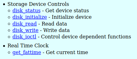
It’s these functions that we’ll need to provide. For an SD card they’re pretty involved, but don’t worry, we’ll just be dropping in a pre-existing driver and linking it up.
Setting up the Project and Pins
- Open STM32CubeIDE.
- Start a new project for the Nucleo-F303RE dev board (or w/e you’re using) called something sensible e.g. cubeide-sd-card.
- Answer ‘Yes’ to Initialize all peripherals in their default configuration?.
- Answer ‘Yes’ to Open device configuration view?.
The Device Configuration View is where you configure exactly which pins/peripherals are enabled and what their settings are. Since we want to be connecting to an SD card, we need to enable an SPI port and then decide where to wire it.
Let’s quickly work out where our pins are going. Our goal here is to identify an SPI peripheral with easy-to-access pins as well as a GPIO pin to use as a chip select.
On the Nucleo-F303-RE we have both Arduino style headers as well as ST’s branded morpho headers, which are the double rows of pins down each side. While it’s tempting to use the Arduino header’s SPI port (since it’s labelled on the silk screen) I actually don’t like to, as the on-board LED shares one of the pins (one of the worst features of this particular development kit). So, instead I will take a look at the morpho header pinouts.
This document from ST provides us with the correct pinout for the F303-RE, or alternatively (and in a more attractive and detailed way) the same info is presented on ST’s mbed OS website here.
Straight away I can see that SPI2 is the winner — it is broken out onto the pins in the bottom right, along with PB1 which we will use for the chip select line.
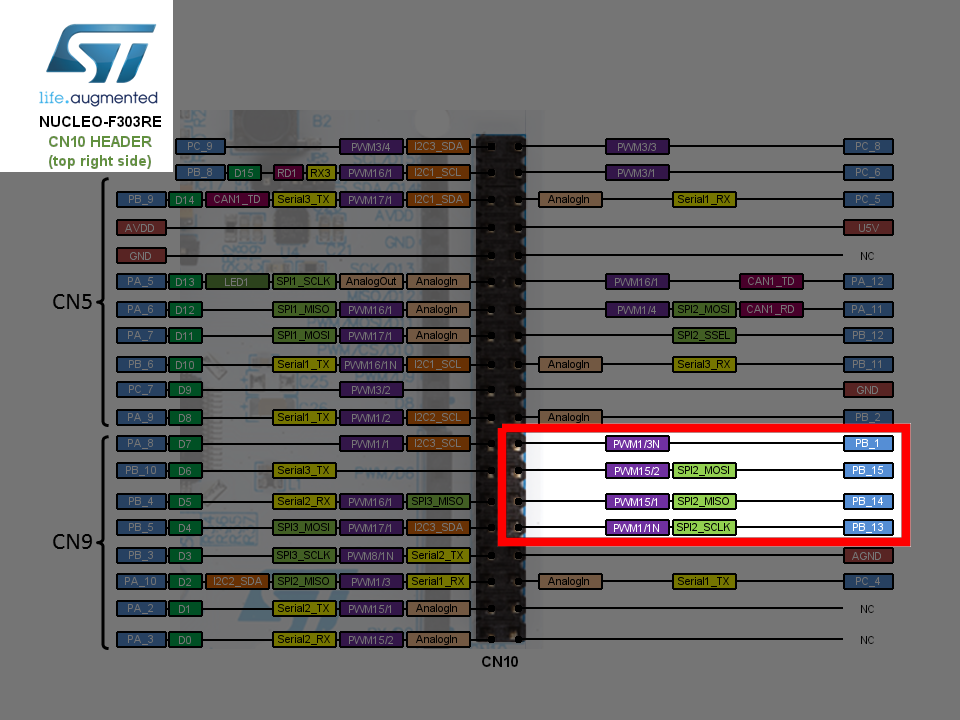
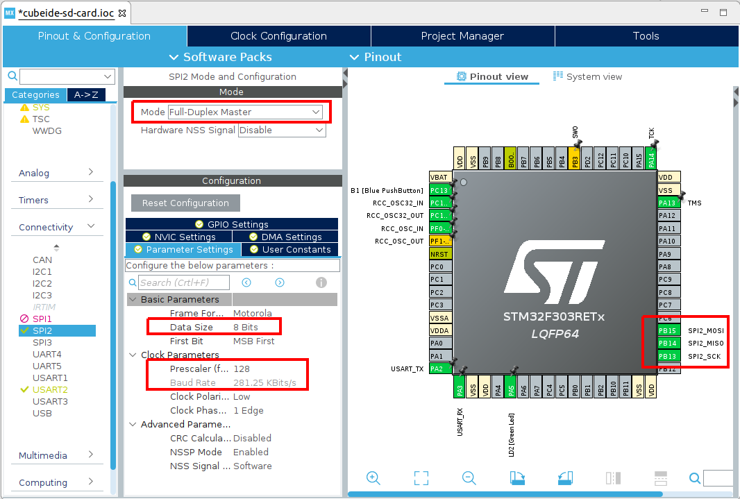
So, let’s set up our SPI2 and GPIO in the Device Configuration View. Click SPI2 on the left, and then set it to Full Duplex Master with no Hardware NSS. Then set the Data Size to 8 bits, and the clock prescaler to 128 (SD cards start up with low speeds and switch to higher speeds later. We’ll look at how to do this soon).
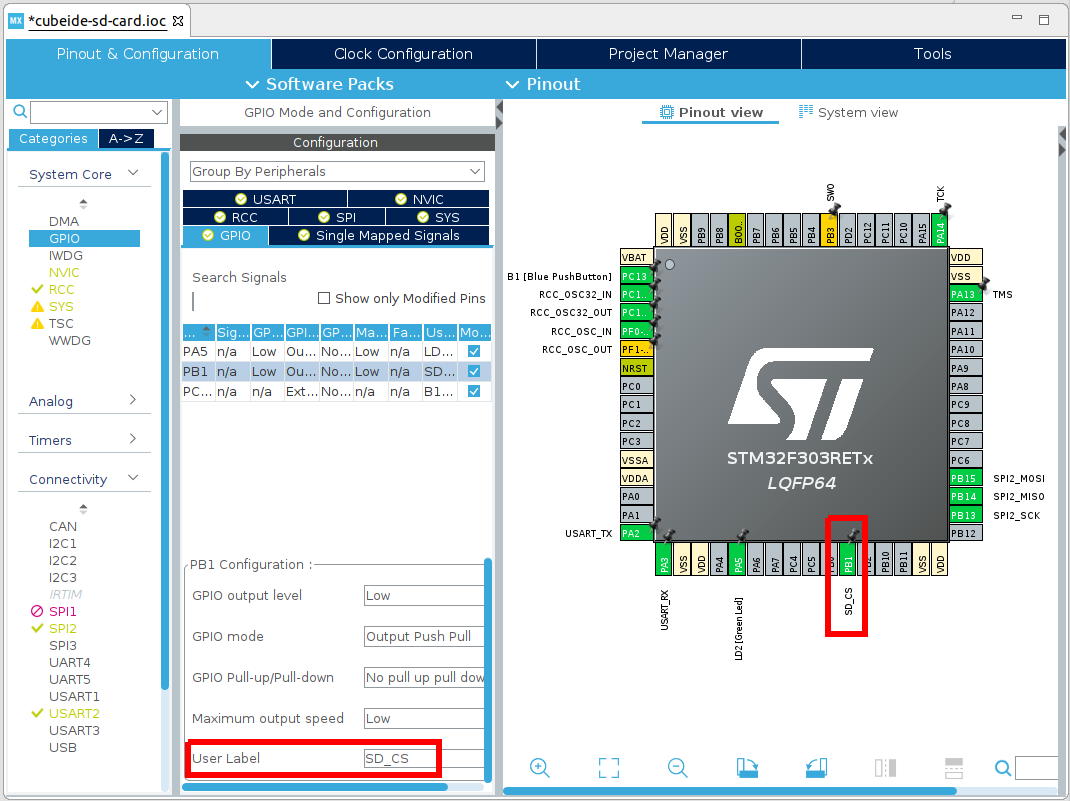
Then, create your Chip Select line on PB1 — I find setting a sensible name is also good:
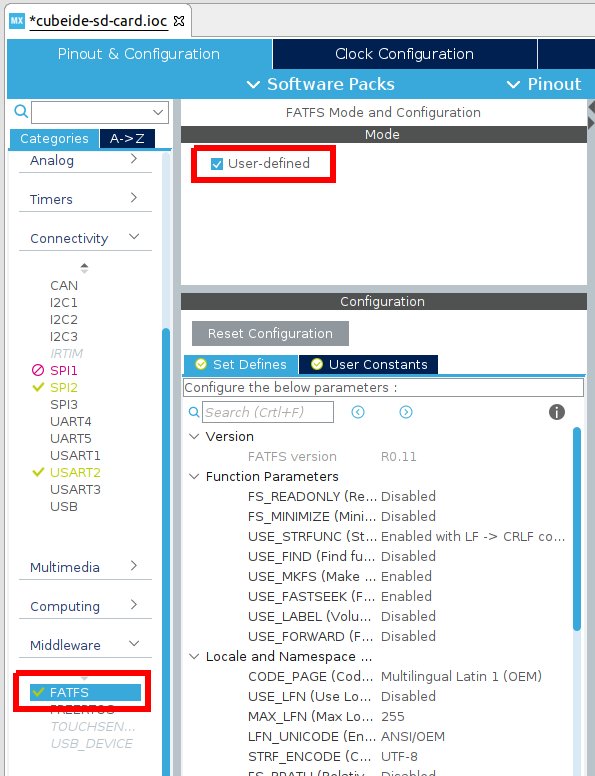
Finally, as we’re going to be using the SD card with the FAT file system, scroll down in the device categories to Middleware , and expand this, then enable FATFS as User-defined . You may leave all other parameters as their defaults.
Now save your Device Configuration, and when it asks, ‘Yes’ to Do you want to generate Code? and ‘Yes’ to Do you want to open [the C/C++] perspective now?.
Wiring the SD card adapter
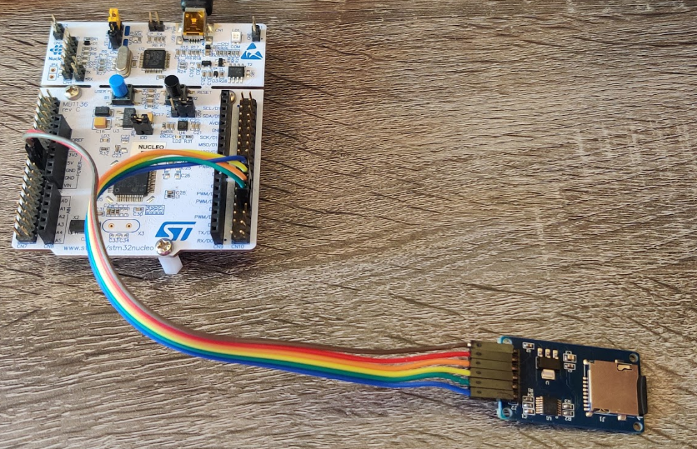
Now that you have configured the pins in CubeIDE, we need to physically wire them in real life!
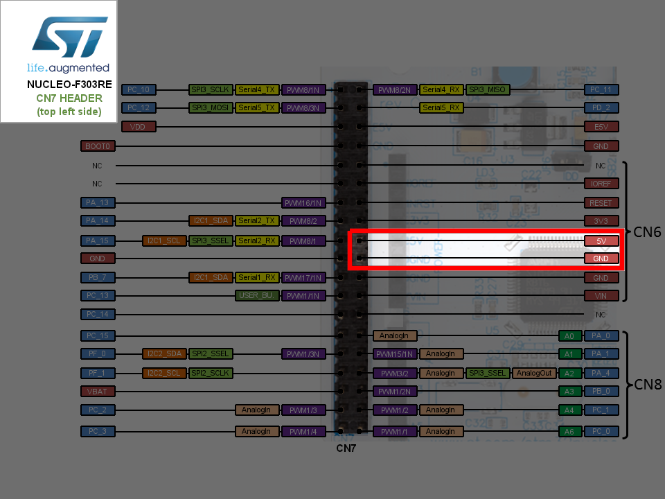
Using the SPI pins from the earlier figure, and the power pins depicted here,
Use your ribbon cables and connect these to the appropriate pins on the SD card adapter module (the module’s pins are labelled on the silk screen, so this isn’t much of a chore).
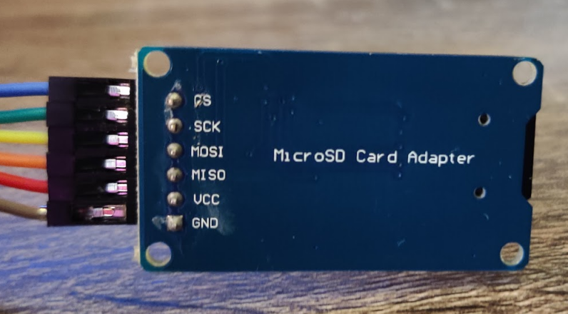
In table form, the connections are as follows:
| SD Adapter side | Nucleo-F303RE side |
|---|---|
| CS | PB1 (GPIO SD_CS) |
| SCK | PB13 (SPI2 SCLK) |
| MOSI | PB15 (SPI2 MOSI) |
| MISO | PB14 (SPI2 MISO) |
| VCC | 5V |
| GND | GND |
Once you’re finished it should look something like this:
Key files to make this work
It’s now time to put our driver in. In 2017 I worked with some of ChaN’s source code to produce a driver compatible with the predecessor to CubeIDE, CubeMX. This driver will work with CubeIDE, but I’ve made a few changes to update it (and make it better). It has two files, user_diskio_spi.c which you can get here, and user_diskio_spi.h which you can get here.
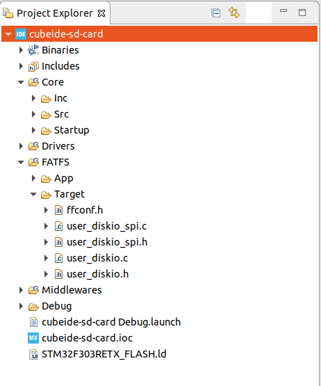
Download these and copy them into your FATFS/Target directory (you can also copy them into Core/Src and Core/Inc respectively if you’d prefer, but I think that’s messier).
When you’ve done this, your file viewer should now look something like this:
Now we need to link the driver into FatFS. This will involve just a simple change to the user_diskio.c file. There are more elegant ways to do this, but if we’re not careful we will fall afoul of the STM32CubeIDE code generator, so we are limited to changing code in the commented areas.
What we’re going to do is embed calls to the SPI driver functions in each of the autogenerated driver stubs. I’ve annotated the changes below with //ADD THIS LINE . You’ll see that each of the function calls just calls the appropriate function in our driver.
In user_diskio.c Decl:
In user_diskio.c Private Functions:
Finally, for our driver to work, we need to make just one more change — we need to tell it which SPI we are using! You’ll notice at the top of user_diskio_spi.c the following snippet:
So this is what we need to do now. Pop over into main.h . You’ll see thanks to our Device configuration from earlier that SD_CS_GPIO_Port and SD_CS_Pin are already set for us, so we only need to add the following line:
in main.h Private defines:
Finally, we need to consider the clock speeds for our SD card driver. If you’re using the Nucleo-F303RE , great, the defaults are what I was using. If not, open up user_diskio_spi.c and just make sure these prescalar values work for you to generate approximately the listed speeds:
We’re ready to go!
Testing and correct output
First, ensure your micro SD card is formatted to the FAT file system (in your operating system of choice just insert the SD card and then format it to FAT32/FAT/msdos — not exFAT).
Then, create a file test.txt in the root of your SD card. Puyt something in it, e.g. Hello I’m on an SD card . Save the file and remove the SD card from your computer.
Now plug the SD card into the module, and connect the development kit to your PC. We’re going to make output will be coming via the integrated COM port, so make sure you open that up using either e.g. minicom (Ubuntu) or PuTTY (Windows).
Now let’s add some code to main.c . We’re going to want a printf that outputs to the integrated terminal, so we need to add a few things:
in main.c Private includes:
in main.c Private function prototypes:
in main.c User Code 0:
Great, that will let us call myprintf() as if it was any other printf with strings of up to 256 characters and the output will come out on UART2 (the virtual COM port).
Now let’s add some file system fun!
in main.c From User Code 2 to User Code 3 (inside the main() function):
Alright, you’re ready to go!
Compile and download the project to your microcontroller. In your terminal, you should see the following appear!
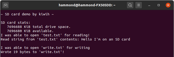
If so, great! If not, rats.
If any numerical errors are given you can convert them into their meaning from the look up table in Middlewares\Third_Party\FatFS\src\ff.h . You should double check your wiring as well. Sadly, not all SD cards will work over SPI — I wasted a good few hours with a Kingston SD card before changing to an Apacer one that just worked instantly. Good luck!
Also note that if you’re using this process with your own custom circuit, you may need pull-up resistors on the SCK, MISO, and MOSI lines. The SD card module I used in this post includes them internally — if you’re wiring your own design, you might find you need to add them. You can also consider enabling the internal pull up resistors. More details are included here.
If you would like the complete code that accompanies this blog post, it is made available in the associated Github repository here.
Записки программиста
Учимся работать с SDHC/SDXC-картами по протоколу SPI
Сегодня SD-карты используются повсюду. Они втыкаются в ноутбуки, планшеты, телефоны, видеокамеры, роутеры, фоторамки, диктофоны, электронные книги, mp3-плееры, одноплатные компьютеры и даже квадрокоптеры — словом, они везде. Часто о них думают, как об относительно медленных устройствах, способных хранить пару гигабайт информации. Однако в наши дни уже доступны SD-карты объемом 512 Гб и скоростью чтения-записи 90 Мбайт/сек (не мегабит!). Теоретически же объем хранимой информации ограничен 2 Тб. А чем еще прекрасны SD-карты, это тем, что с ними можно работать по незамысловатому протоколу, основанному на SPI.
Немного матчасти
«SD» расшифровывается как «Secure Digital». Причем тут безопасность не знает никто. Внутри SD-карты находится обычная flash-память и микроконтроллер, осуществляющий общение с внешним миром. То есть, в первом приближении, это точно такая же non-volatile память, как и SPI flash.
SD-карты бывают трех типов. Карты SDSC (SC = Standard Capacity) позволяют хранить до 2 Гб информации и используют файловую систему FAT12 или FAT16. Эти карты морально устарели, в магазинах их найти непросто, да и по цене они сопоставимы с картами большего объема. Кроме того, они используют протокол, несколько отличающийся от протокола SDHC/SDXC-карт. В силу названных причин, с этого момента про существование SDSC мы забудем. К современным типам карт относятся SDHC (HC = High Capacity), использующие файловую систему FAT32 и способные хранить до 32 Гб данных, а также SDXC (XC = eXtended capacity), использующие exFAT и имеющие объем до 2 Тб. С точки зрения протокола эти карты неотличимы. Разница заключается только в файловой системе, выбор которой диктуется спецификацией.
Разумеется, ничто не мешает отформатировать SDHC карту под exFAT, или SDXC карту под какой-нибудь ZFS. Но ваш смартфон или фотоаппарат, вероятно, не сможет работать с такой картой.
Fun fact! Встречаются поддельные SDHC карты, которые на самом деле являются SDSC. В обычном магазине вы такие, скорее всего, не найдете, а вот на eBay налететь можно. Если вам предлагают купить типа SDHC карту объемом всего лишь 1 Гб, она наверняка на самом деле является SDSC.
Карты разделяют на различные классы, в зависимости от минимальной последовательной скорости записи (обратите внимание на выделение курсивом). Класс скорости обозначают в стиле C4 (class 4) или V30 (class 30). В обоих случаях цифра означает скорость в Мбайт/сек. Отличие C от V заключается только в том, что V намекает на пригодность карты для записи видео высокого разрешения. Еще встречаются маркировки U1 и U3 для 10 Мбайт/сек и 30 Мбайт/сек соответственно, где U означает Ultra High Speed. C10, V10 и U1 — это одно и то же.
SD-карты бывают разных форм-факторов — SD, MiniSD и MicroSD. MiniSD сегодня практически не встречаются. Многие карты выпускаются в форме MicroSD с переходником в обычный SD-формат. Это позволяет покупателям использовать карты с различными устройствами.
На следующем фото изображена моя небольшая коллекция SD и MicroSD-карт, а также модулей для подключения их к отладочным платам (Arduino, Nucleo и подобным):
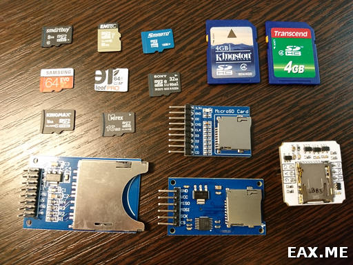
Все представленные здесь модули работают одинаково хорошо. Если сомневаетесь, какой брать — берите тот, что изображен слева внизу. Он позволяет работать как с SD, так и с MicroSD-картами (через переходник), а также имеет дополнительные пины для подключения логического анализатора. Модуль не составляет труда найти на eBay. Еще встречаются модули вообще без резисторов, стабилизаторов напряжения и так далее, имеющие только слот для подключения карты и пины. С ними некоторые карты работать не будут! Далее станет понятно, почему. Наконец, модуль легко спаять из адаптера для MicroSD-карт. Далее будет рассказано, как.
Подключение SD-карты
Ниже изображена распиновка SD и MicroSD-карт:
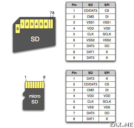
Наибольший интерес для нас представляет правая колонка. На первый вгляд, все просто — смотрим на картинку, хоть напрямую припаиваемся к карте проводами, и начинаем слать и принимать байты по SPI. Но есть ряд важных моментов:
- Ни в коем случае не подавайте 5 В на пин VDD! Все SD-карты гарантировано работают от 3.3 В. Некоторые при этом также могут работать и от 5 В, но это не гарантируется. Если подать 5 В, вы рискуете спалить вашу дорогую карточку на 128 Гб, после чего ее останется только выкинуть;
- По тем же соображениям, если ваш проект использует пятивольтовую логику, крайне рекомендуется использовать конвертер уровней, например TXS0108E (даташит [PDF]);
- Платы Arduino имеют пин 3V3, но не могут подавать на него большой ток. Если запитать SD-карту от этого пина, можно словить забавные глюки. Например, карта будет нормально работать в одиночестве, но переставать работать при подключении к плате TFT-экранчика на базе ST7735, чья подсветка также питается от 3V3. Поэтому, если вы проектируете модуль или Arduino-шилд, используйте понижающий стабилизатор напряжения на 3.3 В вроде AMS1117 ;
- Пин DO (он же MISO) должен быть обязательно подтянут к плюсу через резистор на 10 кОм или около того. Некоторые карты просто не будут стартовать без этого резистора. Например, я наблюдал такое поведение на картах производства Sony;
Теперь становится понятно, почему простые модули, имеющие только слот для подключения карты, не очень подходят. Также теперь ясно, как сделать модуль для подключения MicroSD-карт из адаптера. Отмечу, что пины с землей (VSS1 и VSS2) в адаптере, как правило, уже соединены между собой, поэтому дополнительно соединять их проводочком не требуется. На всякий случай стоит перепроверить, соединены ли пины, прозвонив их мультиметром.
Тонкости протокола
Хорошее описание протокола было найдено в статье How to Use MMC/SDC на сайте elm-chan.org. Здесь я не вижу смысла ее пересказывать. Заинтересованные читатели могут ознакомиться с оригиналом, а также с полной реализацией протокола для микроконтроллеров STM32 в исходниках к данному посту. Вместо пересказа я лишь пробегусь по основным моментам. Также отмечу, что в статье я не нашел упоминание нескольких крайне важных нюансов, про которые будет рассказано далее.
Итак, типичная команда выглядит как-то так:
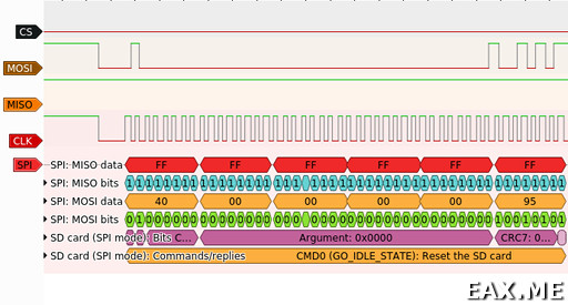
Команды всегда имеют формат 01xxxxxx, и в соответствии со значением битов xxxxxx называются CMD0, CMD1, и так далее до CMD63. Следом за командой идут 4 байта аргумента, за которыми идет байт в формате yyyyyyy1 с семибитным CRC. Контрольные суммы по умолчанию выключены и проверяются только для первых нескольких команд на этапе инициализации. В остальных же случаях CRC заполняется единицами.
Большинство команд получают в ответ один байт, так называемый R1:
Если старший бит ответа равен единице, значит SD-карта еще обрабатывает запрос. Иногда за R1 следуют дополнительные данные. Также в определенных ситуациях в протоколе фигурируют data tokens (байты 0 x FC, 0 x FE), stop transaction token (0 x FD), error token и data response. Детали не слишком захватывающие, к тому же, они хорошо описаны на elm-chan.org и их можно изучить по коду. Куда интереснее то, чего в статье нет или обозначено не слишком явно.
Во-первых, вы можете помнить, что в SPI за один такт SCLK одновременно принимается и передается один бит информации. Так вот, оказывается, что если при чтении ответа от SD-карты случайно послать по SPI что-то отличное от единиц, некоторым SD-картам это рвет башню. Поэтому прием данных от карты выглядит как-то так:
static int SDCARD_ReadBytes ( uint8_t * buff , size_t buff_size ) <
// make sure FF is transmitted during receive
uint8_t tx = 0xFF ;
while ( buff_size > 0 ) <
HAL_SPI_TransmitReceive ( & SDCARD_SPI_PORT , & tx , buff , 1 ,
HAL_MAX_DELAY ) ;
buff ++;
buff_size —;
>
Во-вторых, в статье верно описано, что в определенных случаях карта может помечать себя занятой (busy), притягивая MISO к земле. В таких ситуациях нужно дождаться готовности карты. Но на практике оказалось, что проверку на готовность нужно выполнять перед каждой командой, даже если в текущих обстоятельствах карта не может быть занятой. То есть, по сути, перед каждой командой нужно посылать 0 x FF (на иллюстрации с форматом команд этот момент опущен). Иначе некоторые карты отказываются работать. Я наблюдал такое поведение у карт производства SanDisc.
static int SDCARD_WaitNotBusy ( ) <
uint8_t busy ;
do <
if ( SDCARD_ReadBytes ( & busy , sizeof ( busy ) ) 0 ) <
return — 1 ;
>
> while ( busy != 0xFF ) ;
Fun fact! Понять я это смог, подглядев в Arduino-библиотеку SD. Пользуясь случаем, отмечу, что библиотека эта в целом довольно скверная. Мне не кажется очень хорошей идеей мешать в одну кучу код для SDSC и SDHC/SDXC карт, как сделано в этой библиотеке. Также я заметил, что в ней почему-то отсутствует поддержка CMD18 (READ_MULTIPLE_BLOCK), несмотря на то, что CMD25 (WRITE_MULTIPLE_BLOCK) реализована. И еще библиотека отказалась работать с некоторыми имеющимися у меня картами, несмотря на то, что код, написанный мной с нуля, прекрасно с ними работает. Вот и пользуйся после этого готовыми библиотеками!
Наконец, в третьих, карта может делить SPI-шину с другими устройствами. Понятно, что в этом случае первым делом после запуска прошивки нужно пометить все устройства, как неактивные, подав соответствующее напряжение, обычно высокое, на пины CS. После чего уже можно спокойно общаться с каждым устройством по отдельности, не беспокоясь, что какое-то другое устройство по ошибке решит, что обращались с нему. Но проблема заключается в том, что SD-карта определенным образом интерпретирует данные, передаваемые по SPI, даже не являясь выбранным устройством. Если конкретнее, то при инициализации карты нужно передать 74 или больше единицы (например, 10 байт 0 x FF) с высоким напряжением на CS. По этой причине карта либо должна жить на отдельной шине, либо инициироваться перед всеми остальными устройствами. Иначе карта может отказаться работать, я проверял.
Получившаяся библиотека
В ходе изучения мной протокола SD-карт была написана библиотека для STM32, реализующая этот протокол. Библиотека основана на HAL и имеет следующий интерфейс:
#define SDCARD_SPI_PORT hspi1
#define SDCARD_CS_Pin GPIO_PIN_5 // Arduino shield: D4
#define SDCARD_CS_GPIO_Port GPIOB
extern SPI_HandleTypeDef SDCARD_SPI_PORT ;
// call before initializing any SPI devices
void SDCARD_Unselect ( ) ;
// all procedures return 0 on success,
// size of block == 512 bytes
int SDCARD_Init ( ) ;
int SDCARD_GetBlocksNumber ( uint32_t * num ) ;
int SDCARD_ReadSingleBlock ( uint32_t blockNum , uint8_t * buff ) ;
int SDCARD_WriteSingleBlock ( uint32_t blockNum , const uint8_t * buff ) ;
// Read Multiple Blocks
int SDCARD_ReadBegin ( uint32_t blockNum ) ;
int SDCARD_ReadData ( uint8_t * buff ) ;
int SDCARD_ReadEnd ( ) ;
// Write Multiple Blocks
int SDCARD_WriteBegin ( uint32_t blockNum ) ;
int SDCARD_WriteData ( const uint8_t * buff ) ;
int SDCARD_WriteEnd ( ) ;
SD-карты могут реализовывать дополнительные функции, такие, как очистка блоков и защита блоков от записи. Но они поддерживаются не всеми картами, и потому не реализованы. Также протокол позволяет включить проверку контрольных сумм. Но эта возможность не реализована, поскольку данные могут испортиться не только во время передачи, и потому их целостность должна проверяться выше уровня протокола, на уровне конкретного приложения. Дополнительно вычисляя и проверяя CRC на уровне протокола мы, скорее всего, только зря скушаем миллиамперы и займем flash-память. Да и вообще, я не убежден в надежности семибитных CRC.
Заключение
В качестве источников дополнительной информации я бы рекомендовал следующие:
Полную версию исходников к этому посту вы найдете на GitHub. Обратите внимание, что тамошний пример кода пишет на карту на уровне блоков, ничего не зная ни о каких файловых системах. Поэтому, если решите его запускать, советую выбрать SD-карту без особо ценных данных.
Вооружившись полученными сегодня знаниями, можно реализовать много безумных идей. Например, можно сделать RAID из SD-карточек, или устройство с интерфейсом SD-карты, сжимающее и/или шифрующее данные. Или вообще отправляющее их на сервер по беспроводной связи. Конечно же, совершенно не был затронут вопрос работы с файловыми системами. Ему будет посвящена одна из следующих заметок.
На этом у меня пока все. А доводилось ли вам использовать SD-карты в своих проектах, и если да, то для каких задач?
Вы можете прислать свой комментарий мне на почту, или воспользоваться комментариями в Telegram-группе.