- Sonoff mini: Wi-Fi-реле с DIY-режимом, интеграция в Home Assistant
- Содержание
- Где купить ?
- Параметры
- Поставка
- Внешний вид
- Конструкция
- Приложение Ewelink
- Работа реле
- Режим DIY
- Home Assistant
- Видео версия обзора
- Дополнительные видео по теме:
- Вывод
- #33: Sonoff Mini and S55: ALMOST perfect
- Resources
- Background
- Install Tasmota on Sonoff Mini
- Install Tasmota on Sonoff S55
- 35 thoughts on “ #33: Sonoff Mini and S55: ALMOST perfect ”
Sonoff mini: Wi-Fi-реле с DIY-режимом, интеграция в Home Assistant
Сегодня я расскажу еще про одно умное реле для умного дома — Sonoff mini. На сегодняшний день это самое миниатюрное реле которое побывало у меня в руках, при этом может управляться и при помощи механического выключателя и без паяльника и перепрошивки интегрироваться в Home Assistant .
Содержание
Где купить ?
- Страница продукта — сайт производителя
- Itead.cc — цена на момент публикации $8.49
- Banggood — цена на момент публикации $6.49
- AliExpress — цена на момент публикации $8.49
Параметры
Sonoff mini — представитель новой линейки управляемых устройств. Кроме стандартных возможностей таких как работа через приложение, отложенное включение и выключение и голосовой контроль. Устройство поддерживает DIY режим. Перевод в него осуществляется без необходимости перепрошивки и поддерживает локальное управление при помощи REST команд
Работает реле с нагрузками до 10 Ампер, управляется по wi-fi 2.4 ГГц и имеет размер всего 42 на 20 мм — что позволяет монтировать его в любые подрозетники, тем более что стабильность соединения поддерживает внешняя антенна

Поставка
Поставляется реле в коробочке цвета морской волны, характерной для всех гаджетов новой линейки. Справа вверху имеется логотип DIY.

Для того чтобы лучше понимать миниатюрность этого реле — сравнение его коробки со спичечным коробком. И это не то чтобы какой-то специальный, гигантский коробок — самые обычные, стандартные спички. Реле реально очень маленькое.
В коробке, кроме реле Sonoff mini имеется еще инструкция, рекламный буклет и зип кулек с крохотным джемпером. Джемпер — или замыкатель, это маленькая черная козюлька вверху, предназначена для замыкания контактов и перевода реле в DIY режим
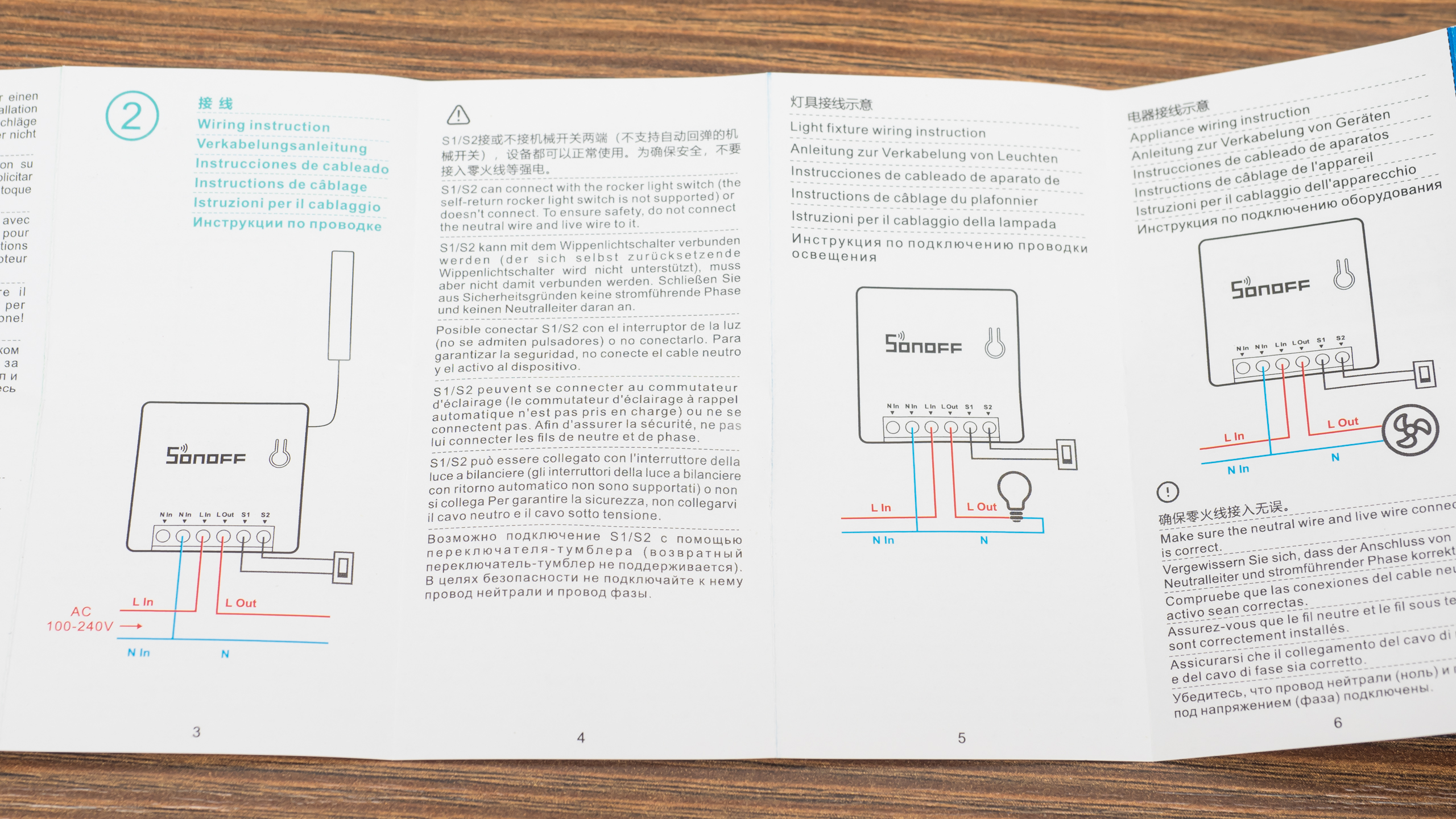
Инструкция на 6 языках в том числе на русском. В ней есть схемы подключения реле и некоторые полезные заметки, например что реле не работает с возвратными выключателями или что провод антенны находится под напряжением
Внешний вид
Реле имеет полностью квадратную форму, с длиной сторон чуть более 4х см и толщиной в 2 см. На одной из сторон находится контактная колодка.

На верхней части находится единственная кнопка для синхронизации и ручного управления. Реле оснащено внешней антенной — для стабильности соединения при внутреннем монтаже.

Еще одно сравнение, с казавшимся раньше небольшим реле sonoff basic — последняя версия с DIY. Ссылка на его обзор.

Конструкция
Реле разбирается легко, корпус состоит из двух половинок и крепится при помощи защелок.
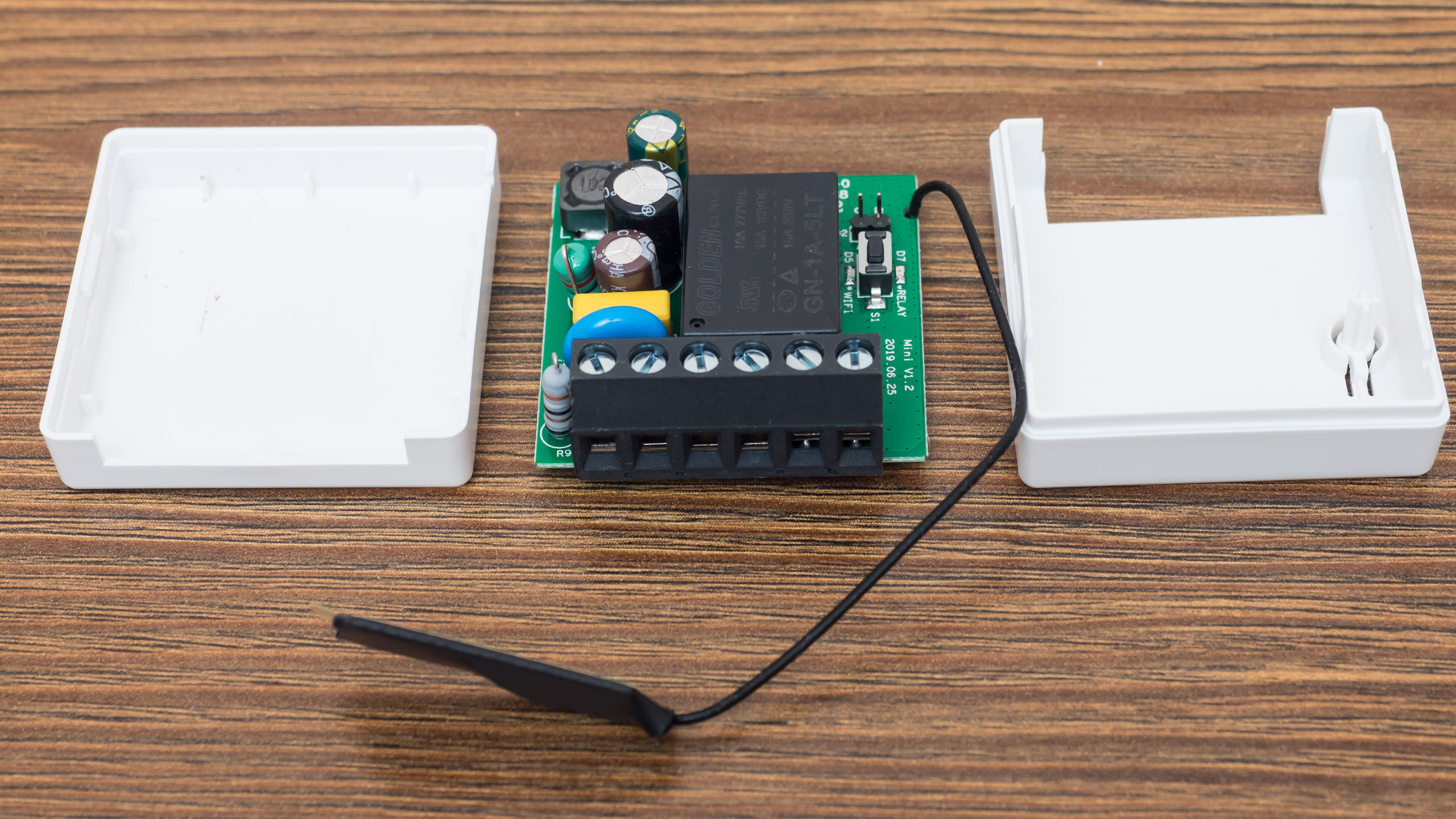
Если считать сторону с контактной колодкой нижней — то справа находится кнопка, контакты для режима DIY и антенна. Слева — силовая часть, трансформатор, электролитические конденсаторы, резисторы — напряжение понижается и выпрямляется для питания электронной части реле
Нижняя сторона — силовые дорожки хорошо пропаяны, следов флюса на плате нет. Нулевые контакты замкнуты между собой. С точки зрения монтажа — наличие двух контактов для ноля — очень удобно. Там же находится и сердце устройства — микроконтроллер ESP 8285, маркировка не очень хорошо видна, и похожа на 8205
Силовой частью ведает реле Golden GN-1a-5LT — на 16 А до 250 Вольт, так что тут имеется солидный запас по мощности

Приложение Ewelink
После подключения питания, реле переходит в режим сопряжения — 2 коротких и один длинный импульс светодиода. Телефон надо перевести на сеть 2.4 ГГц, запустить приложение ewelink и нажать на добавление устройства

Если реле не находится в течении трех минут, то нужно нажать и подержать 5 секунд его кнопку, пока диод снова не начнет моргать в режиме два коротких — один длинный.
После обнаружение и регистрации устройства, что занимает пару минут, остается только дать ему имя и реле готово к работе.
После входа в плагин реле — проверяется и предлагается обновится прошивка. Настоятельно рекомендую это сделать. Чем новее прошивка тем больше допиливают DIY режим. На момент публикации — это 3.3.0
Плагин имеет стандартные для таких устройств функции — в центре кнопка включения / выключения, внизу — дополнительные опции, такие как — предоставление доступа к реле с другого аккаунта, расписание включения или выключения
Два варианта таймера — обычный и циклический, которые тоже могут включать и выключать устройство. Справа вверху — меню настроек.
В меню настроек из интересного есть опция длительность. В которой можно задать интервал от полсекунды до часа. Когда реле включается в этом режиме, оно автоматически отключаться через этот интервал. Как это работает на примере 3х секунд — см. в видео версии обзора
Работа реле
Реле может работать в двух режимах — облачном и LAN. LAN — не зависит от облаков но работает только когда смартфон в той же сети. Но и облачный режим — весьма быстр. См. скорость реагирования в видео версии обзора. Есть две схемы включения реле — стандартный, когда реле управляется только логически (бортовая кнопка не в счет) и когда к контактам S1 и S2 — подключается физический выключатель. Возвратные выключатели не работают!
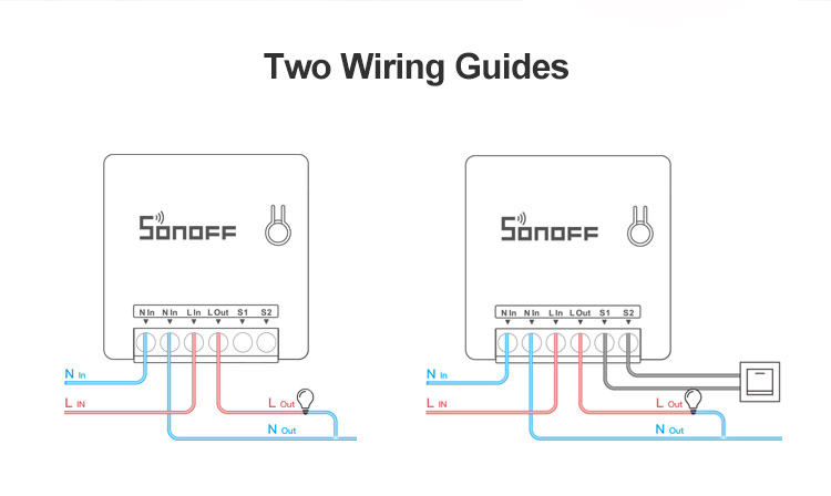
Возможно включение двух выключателей по проходной схеме. Это позволит использовать параллельно с логикой и классический вариант управления, не зависящий от наличия интернет или вай фай.

У выключателя нет положения включено или выключено, он меняет состояние на противоположное. Статус в приложении меняется почти моментально причем это облачный режим работы. (подробнее так же в видео версии)
При активации режима длительность — вне зависимости от способа включения реле отключится через заданный интервал. Это пригодится например для управления воротами, кранами, замками.
Режим DIY
Для активации режима DIY — нужно установить комплектную перемычку на контакты внутри реле. Управление из родного приложения при этом потеряется

Очень подробно про этот режим я рассказывал в обзоре Sonoff Basic, ссылка в описании под видео. Поэтому тут кратко. Нужно активировать на смартфоне точку доступа sonoffDiy с паролем 20170618sn. Реле автоматически подключится к ней.
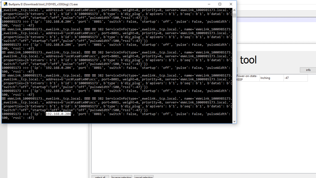
На github странице проекта sonoff diy — качаем консоль управления с логированием tool_01DIY85_v330(log).exe
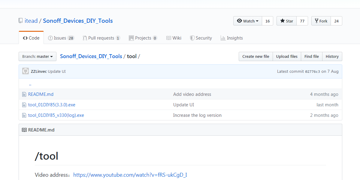
Далее компьютер переключаем в ту же самую сеть — sonoffDiy. И запускаем программу, которая сразу же находит реле
Она позволяет включать и выключать реле, задавать режим при включении. Все заданные параметры видны в окне получения информации — статус и текущие настройки.
При помощи полученных IP адреса и ID номера устройства, которые удобно скопировать из окна логирования
Можно управлять устройством напрямую при помощи REST команд. Подробнее об этом в обзоре Sonoff Basic, а я перейду к интеграции в Home Assistant
Home Assistant
Естественно что для начала нужно перевести реле в основную wi-fi сеть. Это можно сделать и REST командой но проще и быстрее — все тем же приложением через меню change SSID passwrod справа внизу. Задаем имя и пароль сети — применяем полученные параметры и реле теперь соединяется с домашней сетью и становится доступным для управления Home Assistant
ID устройства остается неизменным, а IP адрес меняется уже на тот, что выдает роутер.
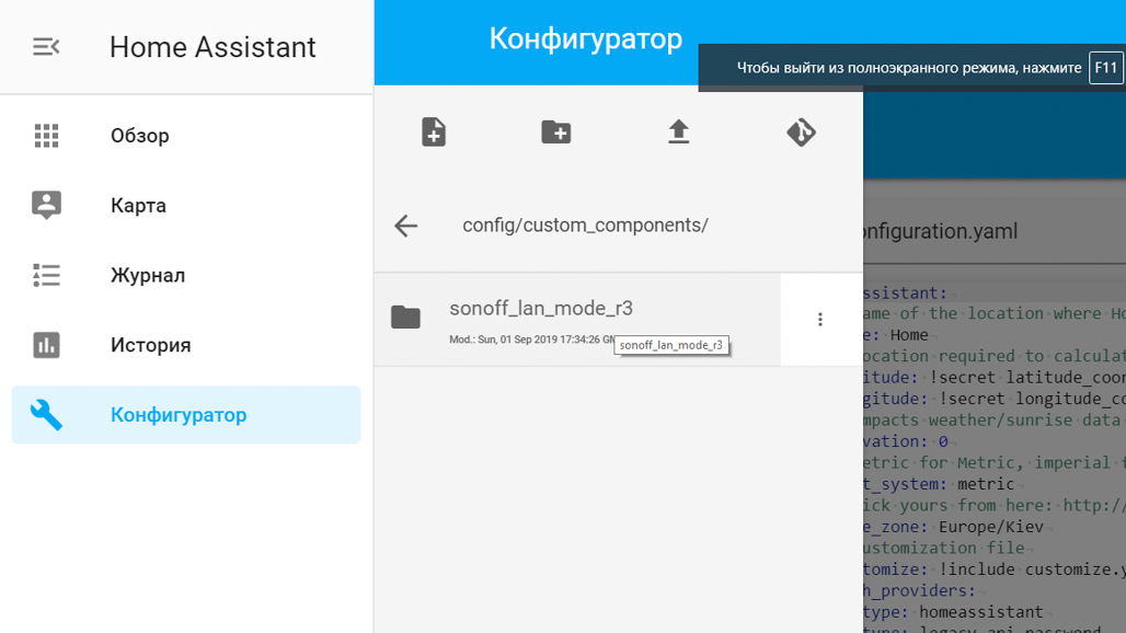
В Home Assistant конечно тоже можно использовать REST команды, как я рассказывал в обзоре Sonoff Basic, но добрые люди, на что я очень надеялся, сделали отдельный компонент — для управления устройствами Sonoff. Качаем архив с github, распаковываем его и записываем его содержимое в папку /custom_components/
Вот так оно должно выглядеть. После этого нужно перегрузить Home Assistant чтобы система знала о новом компоненте
Далее, согласно примеру на githabe прописываем новый swith используя платформу sonoff_lan_mode_r3. При этом нужен только ID устройства. Строка содержащая API ключ для устройств в DIY режиме не надо, нет необходимости прописывать статический IP адрес
После перезагрузки новый выключатель появляется в системе — он полностью функциональный, имеет обратную связь. Естественно что возможность управлять реле при помощи внешнего выключателя — остается
Видео версия обзора
Дополнительные видео по теме:
Вывод
Я считаю что это у Sonoff получился очень удачный продукт. Он позволяет автоматизировать управление различными нагрузками, при этом сохраняя возможность классической схемы с физическим выключателем. Для поклонников системы Home Assistant — имеется легкий путь интеграции без необходимости пайки и прошивки.
#33: Sonoff Mini and S55: ALMOST perfect
The new Sonoff Mini DIY and Sonoff S55 are (so far) the best Sonoff devices that ITEAD has made. Flash them with Tasmota, and they get even better.
Resources
Background
The original Sonoff Basic didn’t have any provision for an external button or switch. One of the most common hacks is to add a switch, so ITEAD decided to make it easy and put screw terminals right there on the Mini.
The Mini is also the smallest Sonoff model so far, which makes it ideal for retrofitting behind an existing switch. Combined with the screw terminals to connect the switch, the Mini is probably the best general-purpose Sonoff for anyone wanting to retrofit home automation to an existing home.
The S55 is an exterior-rated GPO (General Purpose Outlet) or power point. It allows you to have both local control of the power point using a button, and also control from your home automation system.
Both are nice devices, but they become even better when the amazing Open Source Tasmota firmware is installed on them.
Over the years there have been many methods developed to do OTA (Over The Air) replacement of the existing Sonoff firmware with an alternative such as Tasmota. However, I’ve found that these methods are either frustratingly complex or just stop working because ITEAD change things with new releases. I don’t even bother trying these methods anymore: I just go straight to connecting a USB-to-Serial adapter to the programming pins on the Sonoff’s processor. It can be tricky to get the connections sometimes, but it’s guaranteed to work every time single time.
Warning: Do not attempt to connect a programming adapter to any Sonoff model while mains power is connected. ALWAYS disconnect the Sonoff and power it ONLY through the 3.3V connection.
Install Tasmota on Sonoff Mini
The programming connections for the Sonoff Mini are provided on tiny flat pads on the bottom of the PCB:
The button on the top of the PCB is connected to GPIO0, so if you connect to GND, 3.3V, TX, and RX, you can put the Sonoff Mini into programming mode by holding down the button while connecting power from the programmer.
Unfortunately the pads on the PCB are very small, so soldering jumper wires onto them is tricky. If you have a small soldering iron and good eyesight (or magnification) you can solder wires directly onto the pads.
Just be careful you don’t apply too much heat, because the pads can come away from the PCB!
To get around that problem I used my 3D printer to make a programming jig using a design published on Thingiverse. This programming jig uses “pogo pins”, which are spring-loaded pins that can make temporary connections to a PCB. Pogo pins come in a variety of sizes and shapes. I used P75-B1 pins, which means they have a 0.75mm diameter pin with a simple conical point:
This design has 3 parts: a base that holds 4 pogo pins, a small spacer that slips over the pins to help keep them aligned, and a top that goes over the pins and then provides alignment guides for the Sonoff Mini.
I used super-glue to attach the top to the base, once I’d checked everything was aligned:
The Sonoff Mini can be attached using an elastic band:
The pogo pins push against the pads on the PCB:
Hold down the button on the PCB while plugging in the programming adapter to force the Sonoff to go into programming mode, then you can use Esptool or whatever other method you prefer to load the Tasmota binary. In my case I used Esptool, and the command looked like this:
However, this command is specific to the USB port that I used on my computer. You may need to adjust the command to suit your needs. This is all documented well on the Tasmota site.
Because the Sonoff Mini has different pin arrangements to a normal Sonoff Basic, and it’s designed to use a normal switch instead of a button, you need to load a special configuration for it.
After you’ve been through the normal Tasmota setup process and connected it to your WiFi as described in the Tasmota docs, go to the Tasmota templates site at blakadder.github.io/templates/ and search for “Mini”. You’ll find a template that looks like this:
In the Tasmota interface, go to Configuration -> Configure Other and paste the template into the “Template” field.
Make sure the “Activate” check-box is ON, then click “Save”.
Your Sonoff Mini will now operate as expected, with the external switch operating in the normal way.
Install Tasmota on Sonoff S55
The Sonoff S55 doesn’t have a “DIY mode” jumper, so that’s not an option. Luckily, the usual programming header is provided on the PCB ready for you to solder on wires, solder on a header, or just press connections against it. The button for external control is linked to GPIO0, so it’s very easy to put it into programming mode.
The header is in the normal 0.1″ pitch so it’s large enough to solder on a header directly. There’s no need to use a complex pogo pin programming jig.
Solder some hookup wires directly onto the pads, or solder on a header:
I soldered a 4-way 0.1″ header socket onto the pads, with the pins bent a little sideways to make the head sit almost horizontal with the PCB. This makes it easy to plug in a Sonoff Programming Adapter, or use jumper wires to your own USB-to-serial converter.
Hold down the GPIO0 button while you connect the programming header to put it into programming mode, then follow the normal instructions for installing Tasmota. This is very well documented on the Tasmota site.
There’s no specific device profile for the S55 in Tasmota, but it uses the same pinouts as the Sonoff S26 and other mains-plug adapters. Simply select “Sonoff S2x” as the module type in the configuration interface, and it will work as expected.
35 thoughts on “ #33: Sonoff Mini and S55: ALMOST perfect ”
Thx for giving us another great tutorial……
Glad that you are back
Hi,
Have a look at the following Amazon items:
B07FKYT5G8 I have bought three (3) of these three (3) gang wall light switches and loaded Tasmota onto them. They work very well. They work manually as well as via the WiFi (in my case openhab).
One actually drives two (2) down lights (left and right switches) the center switch communicates with openhab and it then Tx’s a IR code for the ceiling fan. ?
I’m about to buy a couple of these GPO’s to give a try for things like Soldering Iron switches ?
B07S942V7L
Just plug the above codes into the Amazon search bar.
Neil
can you please add the flsh gid to your online store? I would buy one and i’m sure others would also.
I will as soon as it’s ready. I’ve done an updated version with auto-reset but the pinout on the programmer probably has to be changed before I release it. It’s all tied up with the “let’s make a standard programming header for ESP8266” discussion at the moment.
Got anywhere with this yet, I want to buy a kit ready made to tazomtize the mini
I am definitely keen on one of these programming jibs also when they are available.
The mini will be great when they make a version that doesn’t require a neutral wire. Like almost every device it suffers from that annoying requirement.
Mainly because it requires both Positive (AC LIVE) and Negative (AC Neutral) to turn on. Try using a device with only one side of the battery connected.
Hello! Do you thin is it posibile so i can but from you a complete programmer set stand and pcb for the sonoff mini?
Hi Jonathan! Actually it’s not needed to solder/dissasemble the Sonoff Mini to upload Tasmota anymore as they have DIY mode from version Jonathan Oxer
Yes, I addressed that in the video. DIY mode is a good idea, but it’s a horrible implementation with an annoying process.
hi Jonathan,
I am just found your channel on youtube and really like all of your ideas .
could you help me with fill things please .
1- in the codes libriary there any thing that will help to slow down a motor after the sensor pass to some point and not let it goes at same speed till the end or when it come back on reverse again slow down.
2- the sonof mini has the S1 S2 pins 3.3 volts . I got some 5 volts infrared to conect on it but want activate the infrared on 3.3 volts any ideia to sorting it .
I was looking about buck converter with LM7805 but I just need get the signal and not sure if really needs it or could use something cheaper like 10k resistor than load the infrared with 5 v to dropping to 3.3
3- the same way I have another problem where I am getting 12 volts signal and want load in the pins S1s2 to put sonoff mini on than was thinking would just resistors to drooping down would be fine or not ?
4 – do you sell this Sonoff Mini Programming Jig’ ? really like the one you did .
1- Sorry, I don’t know what you mean about the codes library, or how this is related to Sonoff. Do you want to control a motor with a Sonoff? If you do, you can’t control the speed.
2 & 3- If you want to trigger the S1/S2 inputs, what it actually needs is to be driven to 0V in an open-collector arrangement. One of those pins is permanently connected to 0V inside the Mini, and the other is connected to a digital pin. It’s watching for the digital pin to be pulled down to 0V.
Instead of a voltage regulator, it sounds like you need a voltage divider. It’s a common technique to convert 5V signals to 3.3V signals. If you search for “voltage divider” you’ll find plenty of examples. But this may not be appropriate either, we’d need to know a lot more about what you’re connecting together to understand the problem you’re trying to solve.
The best thing is to describe what you’re trying to connect on either the Forum or the Discord server (both linked at the top of the page) and discuss it there.
4- I will, but it stalled because of the problem of defining a standard programming header and I need to get back to it.
3-
Do you happen to know exactly what amperage the dc switch loop runs at?
Does anyone?
My testing Sonoff melted and I’m kinda grasping at straws so I won’t need to come back to this a week from now.
hi Jonathan ,
thank you .
1- about reducing the speed of the motor with code come in mind after I tried do something in my gate motor and could not have the board works as I want and also I was the ideia of it is to use in another project use a small servo with gear reduction to turning old door locker … Probably will be easy buy a solenoid locker but I just want adapt it on the actual and have access remotely .
How to Change the Speed of a DC Motor with the Arduino
Sometimes you need to have greater control over the speed of your motor, which the Arduino allows you to do with the MotorSpeed sketch. The following shows you how to control the speed of your motor with the same circuit.
The MotorSpeed sketch
Open a new Arduino sketch, save it with a memorable name, such as myMotorSpeed, and then type the following code.
int motorPin = 9;
void setup() <
pinMode(motorPin, OUTPUT);
>
void loop() <
for(int motorValue = 0 ; motorValue = 0; motorValue -=5) <
analogWrite(motorPin, motorValue);
delay(30);
>
>
After you’ve typed the sketch, save it and press the Compile button to check your code. The Arduino Environment should highlight any grammatical errors in the Message Area if they are discovered.
If the sketch compiles correctly, click Upload to upload the sketch to your board. When uploading is done, you should have a motor that spins very slowly to start with, speeds up to its fastest spin, spins back down to a stop, and then repeats. It can be difficult to see this, so you should fix something more visible, such as adhesive putty, to show you what’s going on.
You may find that at its slowest point, the motor just hums. If so, this is not a problem; it just means that the electromagnet doesn’t have enough voltage to spin the motor; it needs more voltage to generate the magnetism and gain momentum.
The MotorSpeed sketch breakdown
The pin you are using to control the motor circuit, digital pin 9, is declared.
int motorPin = 9;
Because it’s an output, you define it in setup.
void setup() <
pinMode(motorPin, OUTPUT);
>
In the main loop, you use analogWrite to send a PWM value to pin 9. This is the same principle as in the Fade sketch, used to fade an LED. The first for loop sends a gradually increasing value to pin 9 until it reaches the maximum PWM value of 255. The second for loop gradually returns this value to 0; then the cycle repeats itself
void loop() <
for(int motorValue = 0 ; motorValue = 0; motorValue -=5) <
analogWrite(motorPin, motorValue);
delay(30);
>
>
This process could be likened to revving a car engine. If you push the pedal down, you accelerate to full speed. If you tap the gas pedal, the engine accelerates and then slows down. If you tap it at a constant rate before it slows, you will maintain some of the momentum of the spinning motor and achieve an average (if somewhat jerky) speed.
This is what the transistor is doing, but very quickly. The intervals between on and off and the momentum of the motor allow you to achieve analog behavior from a digital signal.