В Arduino реализована аппаратная поддержка интерфейса последовательной передачи данных через выводы 0 и 1 (которые также используются для связи с компьютером посредством USB). Аппаратная работа с последовательным интерфейсом осуществляется с помощью UART. Он позволяет микроконтроллеру Atmega обрабатывать поступающие данные даже во время работы над другими задачами.
Библиотека SoftwareSerial позволяет реализовать последовательный интерфейс на любых других цифровых выводах Arduino с помощью программных средств, дублирующих функциональность UART (отсюда и название «SoftwareSerial»). Библиотека позволяет программно создавать несколько последовательных портов, работающих на скорости до 115200 бод. Для устройств, работающих с инвертированным сигналом, в библиотеке предусмотрен соответствующий параметр, включающий инвертирование.
Среди известных ограничений библиотеки SoftwareSerial можно перечислить следующие:
При использовании нескольких последовательных портов, в каждый момент времени только один из них может получать данные одновременно
На платах Arduino Mega и Mega2560 некоторые выводы не поддерживают прерывания, возникающие при изменении уровня сигнала. В силу этого, на данных платах в качестве вывода RX могут использоваться только следующие выводы: 10, 11, 12, 13, 14, 15, 50, 51, 52, 53, A8 (62), A9 (63), A10 (64), A11 (65), A12 (66), A13 (67), A14 (68), A15 (69)
На Arduino Leonardo некоторые выводы не поддерживают прерывания, возникающие при изменении уровня сигнала. Поэтому, на этой плате в качестве вывода RX могут использоваться только следующие выводы: 8, 9, 10, 11, 14 (MISO), 15 (SCK), 16 (MOSI)
Функции SoftwareSerial
SoftwareSerial() — перед началом работы необходимо вызвать класс с указанием портов для получения и отправки последовательных данных.
Serial
Description
Used for communication between the Arduino board and a computer or other devices. All Arduino boards have at least one serial port (also known as a UART or USART), and some have several.
Board
USB CDC name
Serial pins
Serial1 pins
Serial2 pins
Serial3 pins
Leonardo, Micro, YГєn
Connected to USB
Connected to NINA
SerialUSB (Native USB Port only)
Connected to Programming Port
SerialUSB (Native USB Port only)
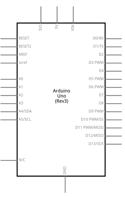
On Uno, Nano, Mini, and Mega, pins 0 and 1 are used for communication with the computer. Connecting anything to these pins can interfere with that communication, including causing failed uploads to the board.
You can use the Arduino environment’s built-in serial monitor to communicate with an Arduino board. Click the serial monitor button in the toolbar and select the same baud rate used in the call to begin() .
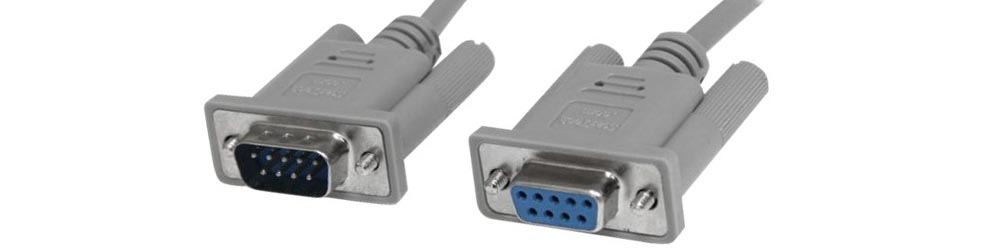
Serial communication on pins TX/RX uses TTL logic levels (5V or 3.3V depending on the board). Don’t connect these pins directly to an RS232 serial port; they operate at +/- 12V and can damage your Arduino board.
To use these extra serial ports to communicate with your personal computer, you will need an additional USB-to-serial adaptor, as they are not connected to the Mega’s USB-to-serial adaptor. To use them to communicate with an external TTL serial device, connect the TX pin to your device’s RX pin, the RX to your device’s TX pin, and the ground of your Mega to your device’s ground.
Software Serial Example
Arduino boards have built in support for serial communication on pins 0 and 1, but what if you need more serial ports? The SoftwareSerial Library has been developed to allow serial communication to take place on the other digital pins of your boards, using software to replicate the functionality of the hardwired RX and TX lines. This can be extremely helpful when the need arises to communicate with two serial enabled devices, or to talk with just one device while leaving the main serial port open for debugging purpose.
In the example below, digital pins 10 and 11 on your Arduino boards are used as virtual RX and TX serial lines. The virtual RX pin is set up to listen for anything coming in on via the main serial line, and to then echo that data out the virtual TX line. Conversely, anything received on the virtual RX is sent out over the hardware TX.
Hardware Required
Circuit
There is no circuit for this example. Make sure that your Arduino board is attached to your computer via USB to enable serial communication through the serial monitor window of the Arduino Software (IDE).
image developed using Fritzing. For more circuit examples, see the Fritzing project page
Schematics
image developed using Fritzing. For more circuit examples, see the Fritzing project page
See also
TwoPortReceive — Two serial ports that receive data switching from one to the other one when a special character is received.
MultiSerialMega — Use two of the serial ports available on the Arduino Mega.
Serial Call Response — Send multiple vairables using a call-and-response (handshaking) method.
Serial Call Response ASCII — Send multiple variables using a call-and-response (handshaking) method, and ASCII-encode the values before sending.
How to use Arduino Software Serial ?
Hello friends, I hope you all are fine and having fun. In today’s tutorial, I am going to show you How to use Arduino Software Serial . In my previous tutorial, we have had a look at How to use Arduino Serial Write and How to use Arduino Serial Read. In both of these tutorials, we have done the hardware Serial Communication. But we all know that Arduino has just one Serial Port placed at pins 0 and 1.
So, if you are having two or more serial modules, then there’s difficulty in adding two modules because we just have one hardware serial port. So, in such cases, there’s a need to add one more serial port and that serial port can be created at any two pins of Arduino and is called software serial . Software Serial is also named Virtual Serial Port .
It’s really very comfy if you are working on serial modules. If you ask me, I have never used a hardware serial port because pin # 0 and pin # 1 are also used for uploading code and debugging the code via Arduino Serial Monitor. So, I always connect my Serial modules via software serial and then check their output on Serial Monitor. So, let’s get started with How to use Arduino Software Serial:
How to use Arduino Software Serial?
I am going to use Proteus software for testing the codes.
You can download the Proteus Simulation for Arduino Software Serial, by clicking the below button:
Download Simulation & Code
Arduino Code
First of all, let me tell you where you can find Examples of Software Serial.
Arduino has a Library of Software Serial in it. If you can’t find its library then you should download the Software Serial Library.
Now copy and paste the below code in your Arduino software:
In the above code, we have first included the Arduino Software Serial Library using #include .
After that, I have created the SoftSerial object and its parameters are SoftSerial(RX, TX) , so in the above code pin # 2 has become RX of our Arduino Software Serial and pin # 3 become TX.
Now our SoftSerial object is ready and then we have initialized our software serial by using SoftSerial.begin(9600) , here we have started our software serial and the baud rate set is 9600.
Proteus Simulation
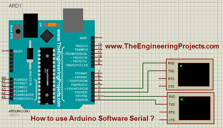
Now design a small circuit in Proteus, you will need Arduino Library for Proteus to use Arduino in Proteus, as shown in the below figure:
Now get the Arduino Hex File and upload it to your Proteus software.
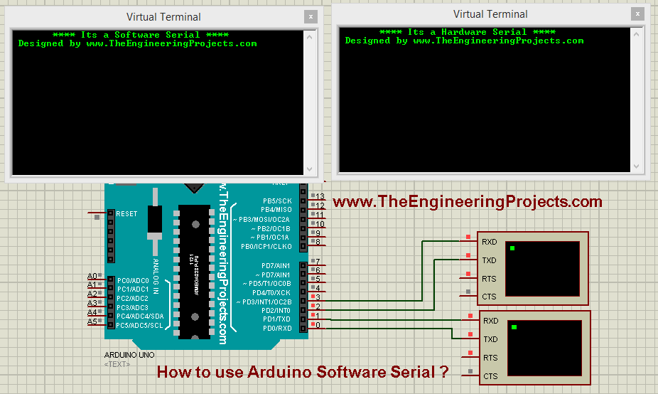
Now run your Proteus Simulation and you will get something as shown in the below figure:
So, it’s printed there that one is hardware serial and second is software serial and you can see the software serial is connected to Pin # 2 and Pin # 3.
Now when you write something in the Hardware Serial, it will also get printed in the Software Serial, that’s the code which we have added in the loop() section.
So, that’s all for today, I hope you have enjoyed this Arduino Software Serial example. Download the Simulation from the above button and try to design it on your own. Take care and have fun . :)
Монитор порта, отладка
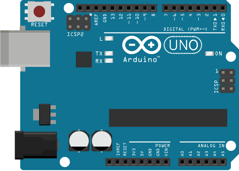
Как мы с вами знаем из урока “Что умеет микроконтроллер“, у многих микроконтроллеров есть интерфейс UART, позволяющий передавать и принимать различные данные. У интерфейса есть два вывода на плате – пины TX и RX. На большинстве Arduino-плат к этим пинам подключен USB-UART преобразователь (расположен на плате), при помощи которого плата может определяться компьютером при подключении USB кабеля и обмениваться с ним информацией. На компьютере создаётся виртуальный COM порт (последовательный порт), к которому можно подключиться при помощи программ-терминалов и принимать-отправлять текстовые данные. Таким же образом кстати работают некоторые принтеры и большинство станков с ЧПУ.
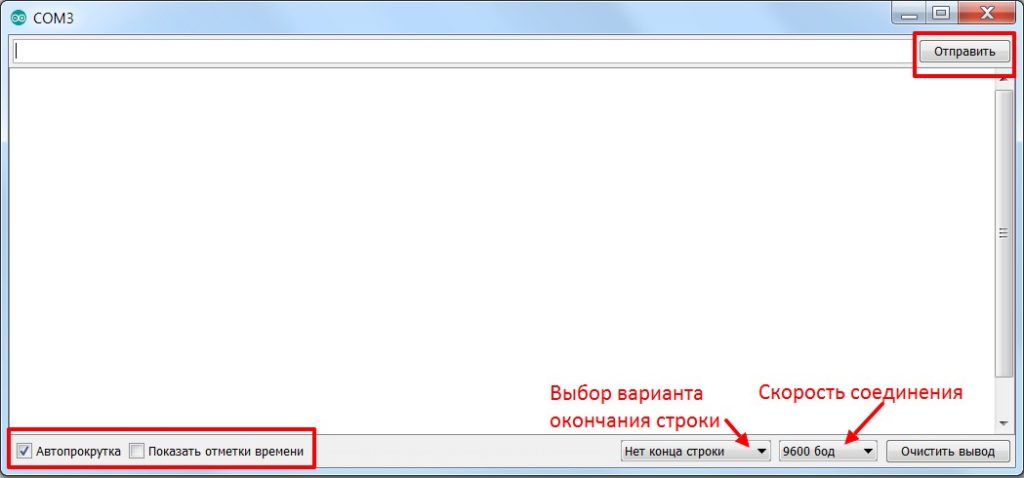
В самой Arduino IDE есть встроенная “консоль” – монитор порта, кнопка с иконкой лупы в правом верхнем углу программы. Нажав на эту кнопку мы откроем сам монитор порта, в котором будут настройки:
Если с отправкой, автопрокруткой, отметками времени и кнопкой очистить вывод всё и так понятно, то конец строки и скорость мы рассмотрим подробнее:
Конец строки: тут есть несколько вариантов на выбор, чуть позже вы поймёте, на что они влияют. Лучше поставить нет конца строки, так как это позволит избежать непонятных ошибок на первых этапах знакомства с платформой.
Нет конца строки – никаких дополнительных символов в конце введённых символов после нажатия на кнопку отправка или клавишу Enter.
NL – символ переноса строки в конце отправленных данных.
CR – символ возврата каретки в конце отправленных данных.
NL+CR – и то и то.
Скорость – тут на выбор нам даётся целый список скоростей, т.к. общение по Serial может осуществляться на разных скоростях, измеряемых в бод (baud), и если скорости приёма и отправки не совпадают – данные будут получены некорректно. По умолчанию скорость стоит 9600, её и оставим.
Объект Serial
Начнём знакомство с одним из самых полезных инструментов Arduino-разработчика – Serial, который идёт в комплекте со стандартными библиотеками. Serial позволяет как просто принимать и отправлять данные через последовательный порт, так и наследует из класса Stream кучу интересных возможностей и фишек, давайте сразу их все рассмотрим, а потом перейдём к конкретным примерам.
Запустить связь по Serial на скорости speed (измеряется в baud, бит в секунду). Скорость можно поставить любую, но есть несколько “стандартных” значений. Список скоростей для монитора порта Arduino IDE:
300
1200
2400
4800
9600 чаще всего используется, можно назвать стандартной
19200
38400
57600
115200 тоже часто встречается
230400
250000
500000
1000000
2000000 – максимальная скорость, не работает на некоторых китайских платах
Похожие записи
Датчик движения для включения освещения Включать освещение в некоторых помещениях или на улице на весь
Проверка датчика температуры охлаждающей жидкости Датчик температуры охлаждающей жидкости — дешевая
Как разобрать ноутбук MSI CX500, CX600 Если вы впервые приступаете к разборке ноутбука, рекомендуем