winneymj/SH1106
Use Git or checkout with SVN using the web URL.
Work fast with our official CLI. Learn more.
Launching GitHub Desktop
If nothing happens, download GitHub Desktop and try again.
Launching GitHub Desktop
If nothing happens, download GitHub Desktop and try again.
Launching Xcode
If nothing happens, download Xcode and try again.
Launching Visual Studio Code
Your codespace will open once ready.
There was a problem preparing your codespace, please try again.
This branch is 10 commits ahead of adafruit:master.
Open a pull request to contribute your changes upstream.
Latest commit
Git stats
Files
Failed to load latest commit information.
README.md
| MCU | Tested Works | Doesn’t Work | Not Tested | Notes |
|---|---|---|---|---|
| Atmega328 @ 16MHz | X | |||
| Atmega328 @ 12MHz | X | |||
| Atmega32u4 @ 16MHz | X | |||
| Atmega32u4 @ 8MHz | X | |||
| ESP8266 | X | change OLED_RESET to different pin if using default I2C pins D4/D5. | ||
| Atmega2560 @ 16MHz | X | |||
| ATSAM3X8E | X | |||
| ATSAM21D | X | |||
| ATtiny85 @ 16MHz | X | |||
| ATtiny85 @ 8MHz | X | |||
| Intel Curie @ 32MHz | X | |||
| STM32F2 | X |
- ATmega328 @ 16MHz : Arduino UNO, Adafruit Pro Trinket 5V, Adafruit Metro 328, Adafruit Metro Mini
- ATmega328 @ 12MHz : Adafruit Pro Trinket 3V
- ATmega32u4 @ 16MHz : Arduino Leonardo, Arduino Micro, Arduino Yun, Teensy 2.0
- ATmega32u4 @ 8MHz : Adafruit Flora, Bluefruit Micro
- ESP8266 : Adafruit Huzzah
- ATmega2560 @ 16MHz : Arduino Mega
- ATSAM3X8E : Arduino Due
- ATSAM21D : Arduino Zero, M0 Pro
- ATtiny85 @ 16MHz : Adafruit Trinket 5V
- ATtiny85 @ 8MHz : Adafruit Gemma, Arduino Gemma, Adafruit Trinket 3V
About
SH1106 oled driver library for ‘monochrome’ 128×64 OLEDs
Arduino Voltmeter using SH1106 OLED display
A voltmeter is an important tool on the workbench of every electronics hobbyist, maker or hardware design engineer. As its name suggests, allows the user to measure the voltage difference between two points. For today’s tutorial, we will look at how you can build an Arduino based DIY voltmeter, for use in situations where you don’t have the standard meters around.
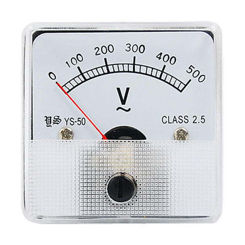 An analog voltmeter
Measuring a DC voltage, should probably be as easy as connecting the voltage to be measured to an analog pin on the Arduino, but this becomes complicated when voltages are higher than the Arduino’s operational voltage (5V). When applied to an analog pin, Arduino will not only give a false reading but it could also damage the board. To solve this, today’s project uses the principle of voltage divider such that only a fraction of the voltage to be measured is applied to the Arduino. This fraction of voltage that goes in is determined by the ratio of the resistors used, as such, there is usually a limit to the maximum voltage that can be applied. For this tutorial, we will use a combo of a 100k and 10k resistor, with the 10k resistor on the “output side”. Feel free to experiment with other resistor values as well.
To make the voltmeter fully functional, we will add a third part, which is an SH1106 controller-based, 1.3″ OLED display, to show the value of the voltage being measured by the voltmeter.
It is important to note that this voltmeter can only monitor DC voltages within the range of 0-30v due to the values of the voltage divider used. It will require a voltage conversion circuit to be able to measure AC voltages.
Required Component
The following components are required to build this project;
- An Arduino UNO board
- 1.3″ (132×64) OLED Display
- 10k Resistor
- 100k Resistor
- A breadboard
- Jumper wires
These components can be bought from any electronics component store online.
Schematics
The schematics for this project is pretty straightforward. The output of the voltage divider is connected to an analog pin on the Arduino while the OLED display is connected to the I2C bus on the Arduino.
Connect the components as shown in the schematics below:
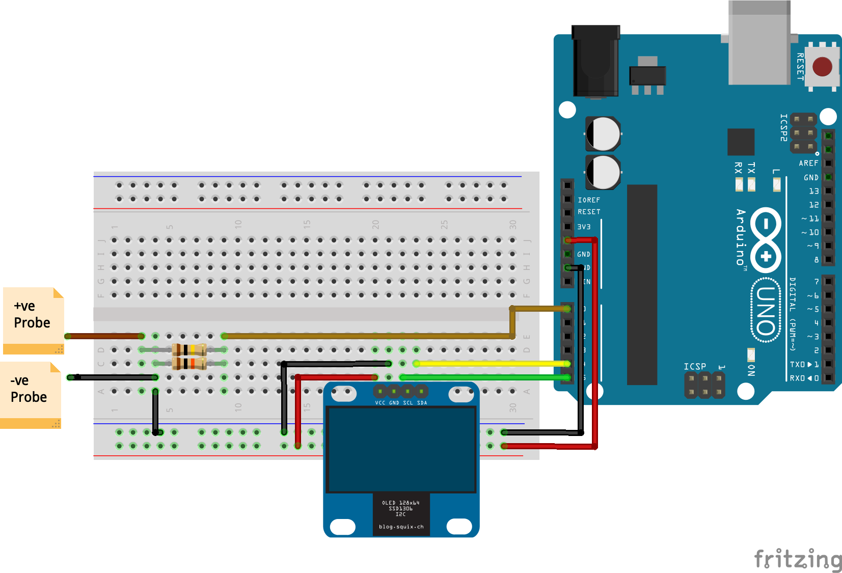 Schematics
As usual, a pin to pin description of the connection between the Arduino and the OLED display is illustrated below.
OLED – Arduino
Go over the connections once again to ensure everything is as it should be.
With the schematics complete we can now write the code for the project. The idea behind the code is simple, read the analog value, process it, then determine the Vin using the voltage divider equation and display it on the OLED display.
To reduce the complexity of the code to interact with the OLED, we will use the U8glib library. The library contains functions which make displaying text and images on the display easy.
To do a quick explanation of the code; We start as usual by including the library that will be used for the project, which in this case is, just the U8glib library.

Next, we specify the analog pin to which the output of our voltage divider is connected and also create variables to hold different parameters including the Vout, Vin and the values of the resistors, correctly initializing their values.
Next, we create an instance/object of the U8glib library, which we will use to interact with the display.
With this done, we move to the void setup() function. While you could do without this content, we proceed to declare the analog pin to which our voltage divider is connected as input.
Next, we proceed to the void loop() function. This is where the main action takes place. We start the function by reading the pin to which the output of the voltage divider is connected. since the value will be expressed in terms of the ADC, we multiply it by 5 and divide by the resolution of the ADC which is 1024 to obtain the decimal value of the voltage at the output of the voltage divider.
We then work our way backward using the Vout and the values of the resistors to determine the value of the input voltage.
To ensure that the value is authentic, we check to ensure that the value is greater than 0.09. If the value is lesser than this, it is rounded up to zero.
Next, we refresh the OLED display and call the draw() function, which is used to print the value of the voltage on the OLED.
A small delay of 500ms is then added to stabilize operations. The loop goes on and on updating the value as soon as there is a change.
The void draw() function is key to the performance of the project’s objectives. The function starts by setting the font in which the texts will be displayed. Next, it displays the text “voltage” and then sets the cursor some few pixels in front of it to display the determined Vin.
The complete code for the project is available below and attached under the download section.
Go over the schematics once again to make sure everything is as it should be, then plug the Arduino to the computer and upload the code. You should see the display come up. At this point, you can now test the voltmeter by connecting the positive (+ve) probe to the positive wire of a battery and the negative probe to the negative wire of the battery. The voltage of that battery should now be displayed on the OLED.
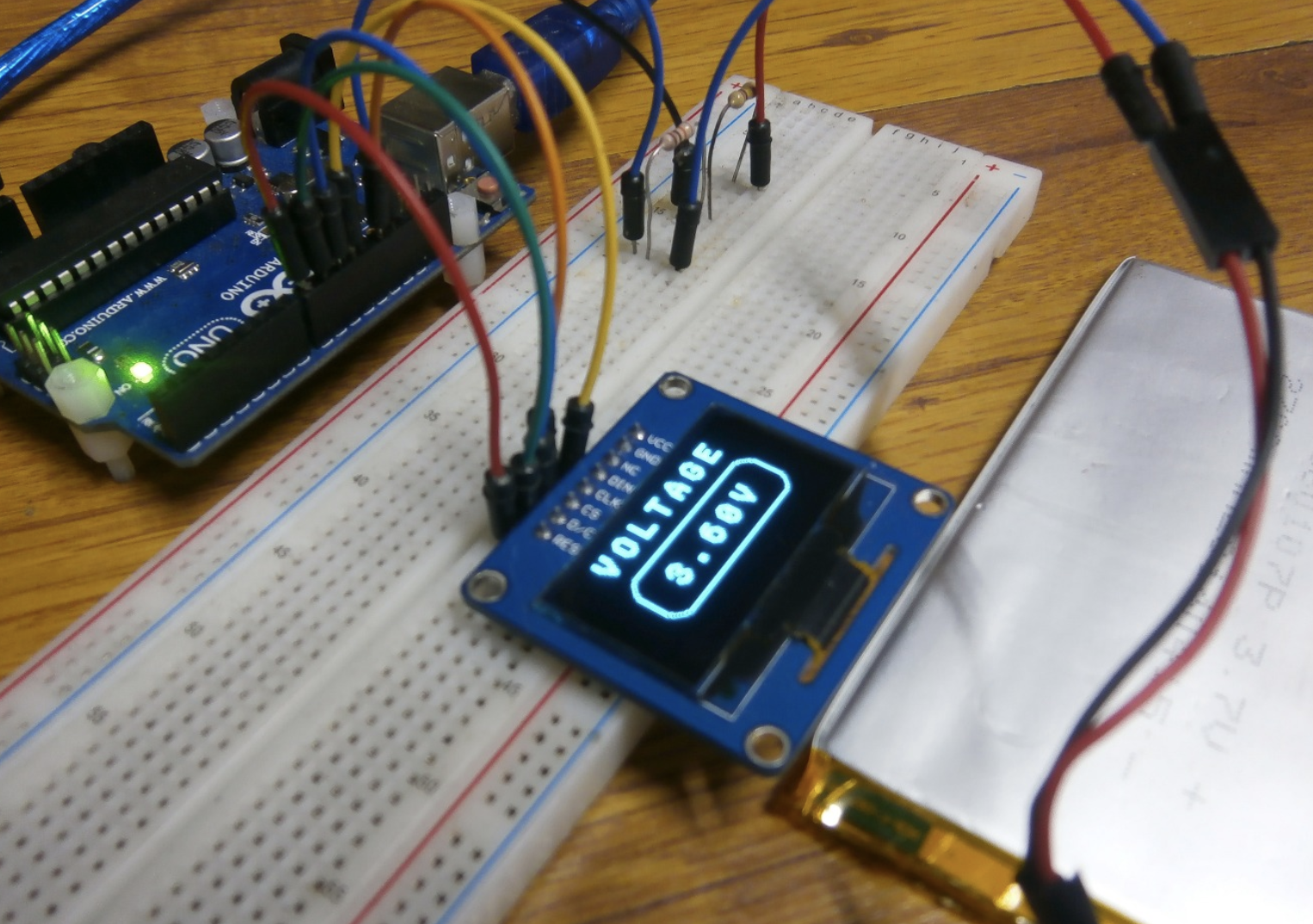 Demo Photo Credit: Konstantin Dimitrov
As mentioned during the introduction, this voltmeter can only be used to measure DC voltages, as such, one improvement that can be made to it going forward is to add the necessary circuits to give it the ability to measure AC voltages or even take it further and add features that allow it measures current, turning it into a full-blown multimeter.
That’s it for this tutorial guys. Feel free to ask whatever questions you might have about the project via the comment section.
notisrac/SH1106Lib
Use Git or checkout with SVN using the web URL.
Work fast with our official CLI. Learn more.
Launching GitHub Desktop
If nothing happens, download GitHub Desktop and try again.
Launching GitHub Desktop
If nothing happens, download GitHub Desktop and try again.
Launching Xcode
If nothing happens, download Xcode and try again.
Launching Visual Studio Code
Your codespace will open once ready.
There was a problem preparing your codespace, please try again.
Latest commit
Git stats
Files
Failed to load latest commit information.
README.md
No buffer SH1106 OLED display driver
An Arduino library for the SH1106 I2C OLED display, for the lower end of the Atmel AVR MCU range that has limited resources. The size is achieved by using libraries that are modular and are size conscious themselves, restricting the featuer list, and eliminating the buffer alltogether.
- Absolutely no buffer
- Minimal RAM (33 bytes) and flash (
2300 bytes) requirement
You must install the following libraries first:
This is the minimal code required to make the library work:
The bare minimum configuration you have to do is telling the SoftI2CMaster what pins to use:
To confugre the underlying two other libraries, check their readmes:
Draw a filled rectangle
Display a bitmap
Converting fonts and bitmaps
To be able to use your fonts/bitmaps with this library, you need to convert it to a specified format. For this you can use the File to C style array converter like this:
- Load the image into the converter («Browse. «, select image, «Open»)
- Set the code format to your liking
- Set the palette mod to 1bit line art
- Tick the Optimize for column read checkbox
- Click «Convert»
- Click «Save as file» OR Click «Copy to clipboard»
- Much slower than a bufferd lib like the U8g2
- Printing text that don’t span the page boundary (aka y % 8 == 0) lines are about 50% faster
- Displaying an image that don’t span the page boundary (aka y % 8 == 0) lines are about 50% faster
- Plotting individual pixels in large numbers is slow
- If constanty updating a text/image on screen, if the design allows it, set the background to SOLID. This is much faster, than clearing the area with fillRect
- Keep in mind, that enabling functions, and adding your own code can increase the size of the binaries pretty fast. So if you can, choose a uc with at least 8k of program space, just to be on the safe side.
Note: all measurements are made on an Arduino UNO with I2C_FASTMODE on, I2C_HARDWARE, I2C_TIMEOUT = 10 and I2C_MAXWAIT = 10
| Library | Prog storage (bytes) | Memory (bytes) | Device support | Comment |
|---|---|---|---|---|
| U8g2 Page buffer mode (Picture Loop) | 9156 | 581 | Almost all of them | Empty example sketch, with lib and init |
| Adafruit_SH1106 | 8726 | 1299 | SH1106 OLED display only | Empty example sketch, init code. This is the Adafruit SSD1306 lib converted to SH1106 |
| SH1106LIB (this lib) | 2312 | 33 | SH1106 OLED display only | Empty example sketch, init code, HW I2C support off, tinyprint off |
Below is a list or AVRs that meet the criteria of running this library — based on their flash and the sram sizes! (4
Initializes the display
void sendCommand(byte c)
Sends a single command to the display
- command: the command (byte) that needs to be sent to the device
void sendData(byte data)
Sends a single byte of data to the display
- data: the data (byte) that needs to be sent to the device
Clears the display
fillRect(uint8_t left, uint8_t top, uint8_t width, uint8_t height, uint8_t color)
Displays a filled rectangle
- left: x coordinate of the top left corner of the rectangle
- top: y coordinate of the top left corner of the rectangle
- width: width of the rectangle
- height: height of the rectangle
- color: color of the rectangle
void drawBitmap(uint8_t x, uint8_t y, const byte *bitmap, uint8_t w, uint8_t h, uint8_t color, uint8_t backgroundType)
Draws a bitmap from the program memory to the display
- x: the x coordinate to put the bitmap
- y: the y coordiante to put the bitmap
- bitmap: the byte array representing the image
- w: the width of the image
- h: the height of the image
- color: the color which the image should be displayed (BLACK/WHITE)
- backgroundType: SOLID or TRANSPARENT background
void drawPixel(uint8_t x, uint8_t y, uint8_t color)
Draws a single pixel on th display
- x: the x coordinate to put the pixel
- y: the y coordiante to put the pixel
- color: the color of the pixel (WHITE or BLACK)
void setCursor(uint8_t x, uint8_t y)
Sets the text cursor to this position
- x: the x coordinate
- y: the y coordiante
void setFont(const unsigned char *font, uint8_t width, uint8_t height, int8_t offset = 0, uint8_t flags = FONT_FULL)
Sets the font to write with
- font: pinter to the array containing the font
- width: the width of the font in pixels
- height: the height of the font in pixels
- offset: signed value to offset the position the character is found in the font
- flags: set of flags describing the properties of the font
void setTextWrap(bool enableWrap)
Sets whether the text should continue on the next row, if it has reached the end of the current one
- enableWrap: true to enable, false to disable
void setTextColor(uint8_t color, uint8_t backgroundType)
Sets whether the text should continue on the next row, if it has reached the end of the current one
- color: the color of the text
- backColor: the color of the background of the text. Set it to TRANSPARENT to have a transparend background
virtual byte write(uint8_t) override
Inherited via TinyPrint Displays a single character
- c: the character to display
- returns: 1
void drawChar(uint8_t x, uint8_t y, uint8_t character, uint8_t color, uint8_t backgroundType)
Draws a character on the screen from the font
- x: x coordinate where the character should be displayed
- y: y coordinate where the character should be displayed
- character: The character to display
- color: the color of the character
- backgroundType: SOLID or TRANSPARENT
- FONT_NUMBERS: the font has numbers
- FONT_UPPERCASECHARS: the font has upper case characters
- FONT_LOWERCASECHARS: the font has lower case characters
- FONT_HASSPACE: the font has a separate character for the space (‘ ‘)
- FONT_FULL: a full font (this has all of the above)
- Write display initialization code
- Implement single pixel drawing
- Implement clearDisplay
- Implement text printing functionality
- Use SoftwareI2CLibrary
- Display bitmaps
- Implement drawLine
- Implement drawCircle
- Implement drawRect
- Put the whole thing into a library format
- Write example codes for lib
- Figure out how the Read Modify Write (RMW) mode works
- Implement fillRect with RMW mode
- Change drawChar to use RMW mode
- Change drawBitmap to use RMW mode
- Do measurements on different devices
About
A no buffer Arduino library for the SH1106 I2C OLED display, for the lower end AVR devices