PIR Motion Sensor
Using a PIR w/Arduino
New Subscription
Please sign in to subscribe to this guide.
You will be redirected back to this guide once you sign in, and can then subscribe to this guide.
Connecting PIR sensors to a microcontroller is really simple. The PIR acts as a digital output, it can be high voltage or low voltage, so all you need to do is listen for the pin to flip high (detected) or low (not detected) by listening on a digital input on your Arduino
Its likely that you’ll want reriggering, so be sure to put the jumper in the H position!
Power the PIR with 5V and connect ground to ground. Then connect the output to a digital pin. In this example we’ll use pin 2.

This guide was first published on Jan 28, 2014. It was last updated on Jan 28, 2014.
This page (Using a PIR w/Arduino) was last updated on Oct 07, 2022.
Text editor powered by tinymce.


OUT OF STOCK NOTIFICATION
You have been successfully subscribed to the Notification List for this product and will therefore receive an e-mail from us when it is back in stock!
For security reasons, an e-mail has been sent to you acknowledging your subscription. Please remember that this subscription will not result in you receiving any e-mail from us about anything other than the restocking of this item.
If, for any reason, you would like to unsubscribe from the Notification List for this product you will find details of how to do so in the e-mail that has just been sent to you!
Interfacing Arduino uno with PIR motion sensor © GPL3+
In this basic tutorial we are going to see how to interface Arduino uno with PIR motion sensor ( HC-SR501 ). So let’s start .
First of all we need to know what is motion sensor and how it works ?
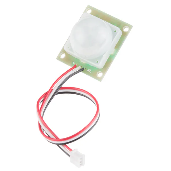
A passive infrared sensor (PIR ) also called as motion sensor is an electronic device which senses motion using a pair of pyroelectric sensors to detect heat energy in the surrounding environment. These two sensors sit beside each other, and when the signal differential between the two sensors changes ( suppose if a person enters the room), the sensor will engage. It basically catches movement. It has three terminals namely Gnd, Vcc and signal pin with 3V regulator, time delay controller, sensitivity controller and BIS001.
PIR terminals — Gnd, Vcc and signal pin. Gnd is considered as the negative pin and is connected to the ground of the system. Vcc basically powers up the pin typically 5V. Signal pin is the output pin.
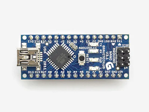
Arduino uno : Arduino Uno is a microcontroller board based on the ATmega328. It has 20 digital input/output pins (of which 6 can be used as PWM outputs and 6 can be used as analog inputs), a 16 MHz resonator, a USB connection, a power jack, an in-circuit system programming (ICSP) header, and a reset button.
Now we can start working on the circuit :
PIR connections — Connect the Gnd pin of sensor to the ground of Arduino. Vcc pin of the sensor to 5V of Arduino. And signal / output pin to digital pin 5 of Arduino board.
Led connections — Positive terminal of the led to digital pin 9 of Arduino. Negative terminal should be connected to any one leg of resistor. Another leg of the resistor should be connected to Gnd of Arduino.
Refer the circuit diagram for better understanding. Circuit diagram is also uploaded in the hardware section so that you can download.
PIR Sensor Tutorial — With Or Out Arduino
Just before creating my next tutorial, which will be using a PIR sensor, I thought I might create a separate tutorial for PIR Sensor.
 |
| × | 1 | |
 |
| × | 1 | |
 |
| × | 1 | |
| × | 1 | ||
| × | 1 | ||
 |
| × | 1 | |
| × | 1 |
Just before creating my next projects tutorial, which will be using a PIR sensor, I thought I might create a separate tutorial explaining the working of a PIR sensor. By doing that I will be able to keep my other tutorial short and to the point. So, without wasting time let’s discuss what is a PIR sensor and how we can use it in our project.
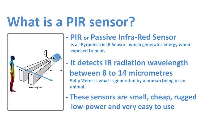
What is a PIR sensor?PIR or «Passive Infra-Red» sensor is a «Pyroelectric IR Sensor» which generates energy when exposed to heat. Everything emits some low level of radiation, the hotter the object is, the more radiation is emitted. When a human or an animal (with IR radiation wavelength of 9.4µMeter) approaches the sensors range the sensor detects the heat in the form of infrared radiation. The sensor only detects the energy emitted by other objects and don’t produce any, that’s why the sensor is called a PIR or «Passive Infra-Red» sensor. These sensors are small, cheap, rugged, low-power and very easy to use.
Step 2: Hardware
For this tutorial we need:
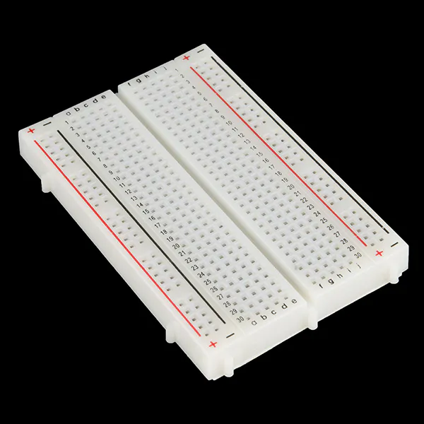
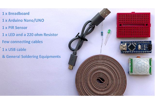
- 1 x Breadboard
- 1 x Arduino Nano/UNO (Whatever is handy)
- 1 x PIR Sensor
- 1 x LED and a 220 ohm current limiting resistor to test the connectivity
- Few connecting cables
- A USB cable to upload the code to the Arduino
- General Soldering Equipment
Step 3: Architecture
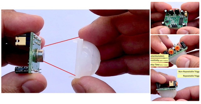
As we can see the sensor has two sides:
- Top or the Sensor Side
- Bottom or the Components Side
The Top consist of a specially designed ‘High-Density Polythene’ cover called «Fresnel Lens». This lens focuses the infrared rays to the underlying ‘Pyroelectric Sensor’. 9.4 µMeter infrared rays can easily pass through the polyethylene cover. The sensors sensitivity range between 6 to 7 meters (20 feet) and the detection angle is 110 degrees x 70 degrees. The actual sensor is inside a sealed metal can. The can basically protects the sensor from noise, temperature and humidity.
There is a tiny window made of IR-transmissive material to allow the IR signals to reach the sensor. Behind this window are ‘two’ balanced PIR sensors. In idle state, both sensors detect the same amount of IR radiation. When a warm body passes by, it first intercepts one of the two sensors, causing a positive differential change between the two halves. And then, when it leaves the sensing area, the reverse happens, and the sensor generates a negative differential change. When the pulse changes or in other words the PIR sensor detects motion, the output pin changes to «digital high» or 3.3V.The bottom bit consists of a bunch of circuitry. Few of them are of our interest
Most PIR sensors have 3-pins: VCC, GND and OUT. VCC and GND are to power the module (Operating voltage: DC 5V to 20V). The OUTPUT pin is the one which communicates with the micro-controller by sending digital pulse high (3.3v) when a motion is detected and digital low (0v) when no motion is detected. The pin-outs may vary between modules so always triple-check the pin-outs.- The BISS0001 or the «Micro Power PIR Motion Detector IC» gets the output from the sensor and after doing some minor processing it produces the digital output.- The module has two potentiometers one to adjust the sensitivity (which is up to 7m) and the other to adjust the time for which the output signal should stay high when an object is detected (it ranges from 0.3s to 5 mins).- There are 3 more pins on this module with a jumper between them to select the trigger modes.> 1st one is called «non-repeatable trigger» — this one goes low as soon as the delay time is over.> 2nd one is called «repeatable trigger» — it stays high as long as the object is in the proximity and will turn off once the object is gone and the delay is over. I will be using this mode for this project.If you want to do a quick test before going ahead with this tutorial please follow the steps below.A testing is also a good idea to test the range and duration of sensing.
Step 4: Connecting Without Arduino
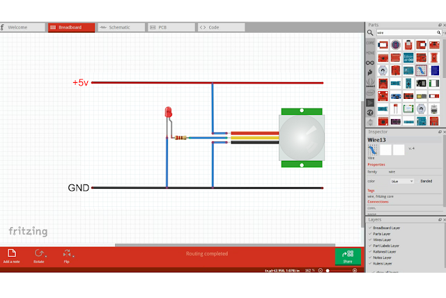
- Connect the VCC to the +5v rail of the breadboard
- Connect the GND to the -ve rail
- Connect the LED along with a 220 ohm resistor to the OUT pin of the sensorNow, when the sensor detects a motion, the output pin will go «high» and the LED will light up.
Move back and forward to find out the sensing the range. Then to test the duration walk in front of the sensor and then walk away and use a stopwatch to find out how long the LED stayed on. You can adjust the time or sensitivity by adjusting the POTs on the board.
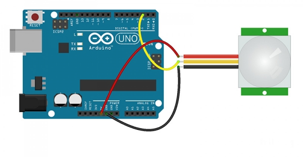
Step 5: Connecting With Arduino
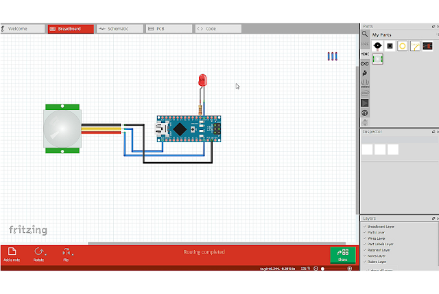
Now, to do the same with Arduino connect the VCC of the PIR sensor to the 5v pin of Arduino.Then connect the OUTput pin to D13 and GND to the Ground pin of the Arduino. Now, connect the LED along with a 220 ohm resistor to the D2 pin of the Arduino. Thats it, now you just need to upload the code and test if everything works the way it should. You can replace the LED with a Buzzer (to raise an alarm when an object is detected) or a Relay to drive a high voltage circuit.To learn more about relays please have a look at my tutorial Number 4 — «Driving a Relay with an Arduino». https://www.instructables.com/id/Driving-a-Relay-W.
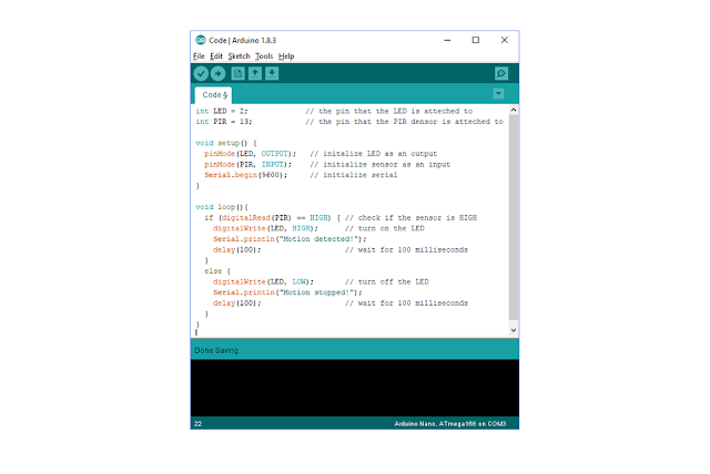
The code is very simple* Start by defining the pin number 2 and 13 as LED pin and PIR pin respectively* Then we need to define the pin modes. LED pin to be the OUTPUT pin and PIR pin to be the INPUT pin* Next we need to read the value of the PIR pin and see if it is HIGH* If the value is HIGH, then turn ON the LED otherwise turn it OFF
Step 7: Areas of Application of PIR Sensors
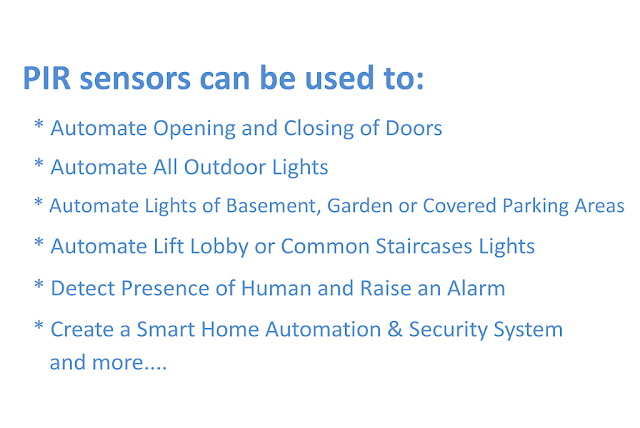
PIR sensors can be used to:
- Automate Opening and Closing of Doors
- Automate All Outdoor Lights
- Automate Lights of Basement, Garden or Covered Parking Areas
- Automate Lift Lobby or Common Staircases Lights
- Detect Presence of Human and Raise an Alarm
- Create a Smart Home Automation & Security System, and many more.
PIR Motion Sensor: How to Use PIRs w/ Arduino & Raspberry Pi © GPL3+
Learn how to use a PIR motion sensor to detect movement. You will also learn how PIR motion sensors work and how to use them.
You can read this and other amazing tutorials on ElectroPeak’s official website
How PIR Motion Sensors Work
Passive Infra Red sensors can detect movement of objects that radiate IR light (like human bodies). Therefore, using these sensors to detect human movement or occupancy in security systems is very common. Initial setup and calibration of these sensors takes about 10 to 60 seconds.
The HC-SR501’s infrared imaging sensor is an efficient, inexpensive and adjustable module for detecting motion in the environment. The small size and physical design of this module allow you to easily use it in your project.
The output of PIR motion detection sensor can be connected directly to one of the Arduino (or any microcontroller) digital pins. If any motion is detected by the sensor, this pin value will be set to “1”. The two potentiometers on the board allow you to adjust the sensitivity and delay time after detecting a movement.
_f6ucGPuaDx.jpg)
PIR modules have a passive infrared sensor that detects the occupancy and movement from the infrared radiated from human body. You can use this module in security systems, smart lighting systems, automation, etc. There are different PIR modules available in the market, but all of them are basically the same. They all have at least a Vcc pin, GND pin, and digital output. In some of these modules, there is a ball like a lens on the sensor that improves the viewing angle.
_nYXUc5buTZ.jpg)
Using a PIR Sensor with Arduino
Circuit
You can connect PIR output to any digital pin.
There is a jumper behind this module. If you move the jumper to L position, the sensor will ‘toggle’ (change state) whenever motion is detected. This is unlikely to be of much use in a practical applications. This mode is called non-triggering or Single Triggering mode.
Moving the jumper to the H position will result in the more usual sensor logic. The sensor will turn on when motion is detected and turn off a while after the last motion is detected. This sensor will reset the timer (which would otherwise turn the output off) each time motion is detected; this would be applicable, for example, for room occupancy lighting control where you don’t want the lights to blink off while the unit resets. This is called Retriggering mode. (or repeatable trigger mode).
There are also two potentiometers behind this module. By changing the SENSITIVITY potentiometer, you can reduce or increase the sensitivity of the sensor (clockwise increase), and also by changing TIME potentiometer the output delay after movement detection will be changed.
Code
You must add the library and then upload the code. If it is the first time you run an Arduino board, Just follow these steps:
- Go to www.arduino.cc/en/Main/Software and download the software of your OS. Install the IDE software as instructed.
- Run the Arduino IDE and clear the text editor and copy the following code in the text editor.
- Choose the board in tools and boards, then select your Arduino Board.
- Connect the Arduino to your PC and set the COM port in tools and port.
- Press the Upload (Arrow sign) button.
- You are all set!
For proper calibration, there should not be any movement in front of the PIR sensor for up to 15 seconds (until pin 13 is turned off). After this period, the sensor has a snapshot of its viewing area and it can detect movements. When the PIR sensor detects a movement, the output will be HIGH, otherwise, it will be LOW.