Учебное пособие по акселерометру и гироскопу MPU6050. Подключение к Ардуино
В этой статье мы узнаем, как использовать акселерометр и датчик гироскопа MPU6050 совместно с Ардуино. Объясним, как работает MPU6050 и как считывать с него данные.
MPU6050 — как это работает
MPU6050 имеет 3-осевой акселерометр и 3-осевой гироскоп, интегрированные в один чип. Гироскоп измеряет скорость вращения или скорость изменения углового положения во времени по осям X, Y и Z. Для измерения используется технология MEMS и эффект Кориолиса.
Выходные данные гироскопа измеряются в градусах в секунду, поэтому для получения углового положения нам просто нужно интегрировать угловую скорость.
С другой стороны, акселерометр MPU6050 измеряет ускорение. Вкратце, он может измерять гравитационное ускорение по трем осям, и используя некоторую тригонометрию, мы можем вычислить угол, под которым расположен датчик. Итак, если мы объединим данные акселерометра и гироскопа, мы сможем получить очень точную информацию об ориентации датчика в пространстве.

MPU6050 также называют устройством слежения за движением по шести осям или устройством с 6 степенями свободы (шесть степеней свободы) из-за его 6 выходов, или 3 выхода акселерометра и 3 выхода гироскопа.
Ардуино и MPU6050
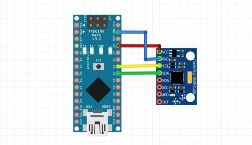
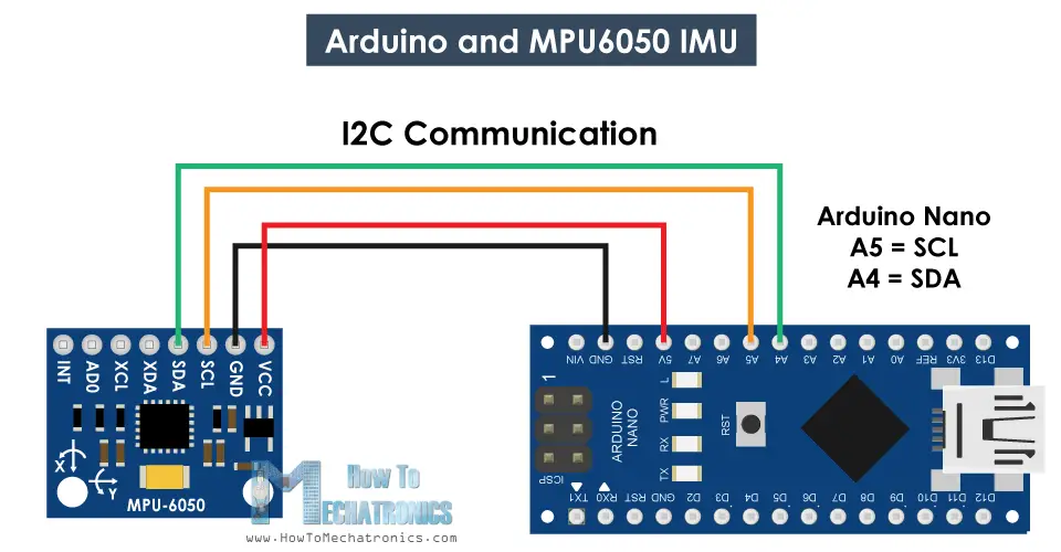
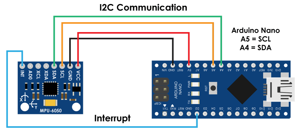
Давайте посмотрим, как мы можем подключить и прочитать данные с датчика MPU6050 с помощью Ардуино. Для связи с Ардуино мы используем протокол I2C, поэтому нам нужны всего два провода для подключения по линии данных и два провода для питания.

Скетч MPU6050 Ардуино
Ниже приведем полный код, а после разъясним его поподробнее:
Описание кода: Итак, сначала нам нужно подключить библиотеку Wire.h, которая используется для I2C связи, и определить некоторые переменные, необходимые для хранения данных.
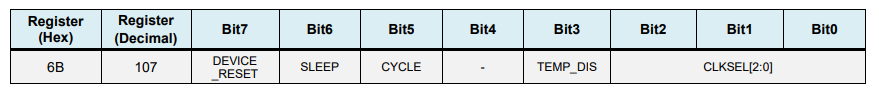
В разделе setup() нам нужно инициализировать библиотеку Wire.h и сбросить датчик через регистр управления . Для этого нам нужно взглянуть в datasheet, где мы можем увидеть адрес регистра:

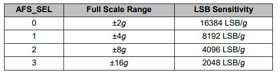
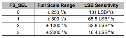
Также, если мы хотим, мы можем выбрать полный диапазон для акселерометра и гироскопа, используя их регистры конфигурации. В этом примере мы будем использовать диапазон по умолчанию + — 2g для акселерометра и диапазон 250 градусов/с для гироскопа, поэтому оставим эту часть кода закомментированной:
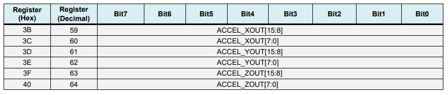
В разделе loop() мы начинаем с чтения данных акселерометра. Данные для каждой оси хранятся в двух байтах или регистрах, и мы можем видеть адреса этих регистров в datasheet датчика:

Чтобы прочитать их все, мы начинаем с первого регистра и с помощью функции RequiestFrom() запрашиваем чтение всех 6 регистров для осей X, Y и Z. Затем мы читаем данные из каждого регистра, и, поскольку выходные данные состроят из старшего и младшего байта, мы соответствующим образом объединяем их, чтобы получить правильные значения:
Чтобы получить выходные значения от -1g до + 1g, подходящие для расчета углов, мы делим выходной сигнал с предварительно выбранной чувствительностью.

Наконец, используя две формулы, мы вычисляем углы крена и тангажа на основе данных акселерометра:
Далее тем же методом получаем данные гироскопа:

Мы считываем шесть регистров гироскопа, соответствующим образом объединяем их данные и делим их на предварительно выбранную чувствительность, чтобы получить результат в градусах в секунду:

Здесь вы можете заметить, что выходные значения корректируются на величину ошибок (объясним далее). Поскольку выходные данные выражаются в градусах в секунду, то нам нужно умножить их на время, чтобы получить только градусы. Значение времени фиксируется перед каждой итерацией чтения с помощью функции millis().
Наконец, мы объединяем данные акселерометра и гироскопа с помощью дополнительного фильтра. Здесь мы берем 96% данных гироскопа, потому что они очень точны и не подвержены внешним воздействиям.
Обратной стороной гироскопа является то, что он дрейфует или вносит ошибку в выходной сигнал с течением времени. Поэтому в долгосрочной перспективе мы используем данные акселерометра, в данном случае 4%, что достаточно для устранения ошибки дрейфа гироскопа.
Однако, поскольку мы не можем рассчитать рыскание по данным акселерометра, мы не можем реализовать для него дополнительный фильтр.
Прежде чем мы взглянем на результаты, объясним, как получить значения коррекции ошибок. Для вычисления этих ошибок мы можем вызвать пользовательскую функцию calculate_IMU_error(), когда датчик находится в неподвижном положении.
Здесь мы делаем 200 измерений для всех выходов, суммируем их и делим на 200. Поскольку мы удерживаем датчик в горизонтальном неподвижном положении, ожидаемые выходные значения должны быть 0. Таким образом, с помощью этого расчета мы можем получить среднюю ошибку датчика.
Мы просто печатаем значения на последовательном мониторе, и, узнав их, мы можем реализовать их в коде, как показано ранее, как для расчета крена, так и для тангажа, а также для трех выходов гироскопа.
MPU 6050 Tutorial | How to Program MPU 6050 With Arduino © CC BY-NC
Hello all, welcome to another Arduino Sensor Tutorial, in this Blog, we will learn how to wire and code MPU 6050, lets start!
Hello all, welcome to another Arduino Sensor Tutorial, in this Blog, we will learn how to wire and code MPU 6050 which is a 6 axis Accelerometer, with our Arduino Board, in detail, so follow till end!
Hardware
Software
Step 1: Watch the Video Tutorial
Step 2: Introduction
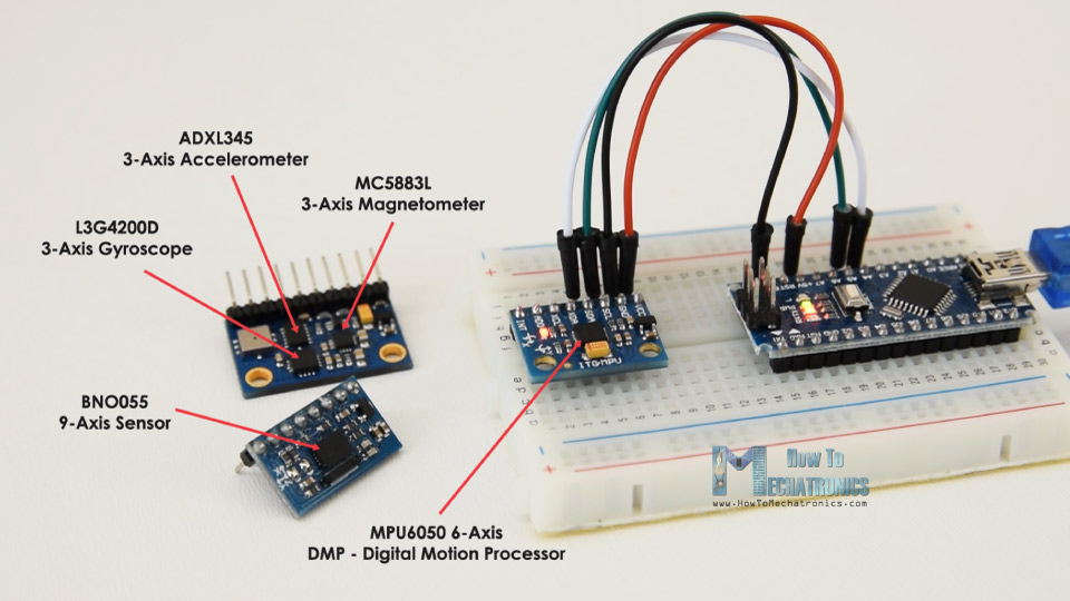
MPU6050 is the world’s first integrated 6-axis Motion Tracking device that combines a 3-axis gyroscope, 3-axis accelerometer, and a Digital Motion Processor™ (DMP) all in a small 4x4x0.9mm package which is theIntegrated Circuit in Middle, it is based on I2C communication protocol, rather than discussing the specifics, refer the Datasheet of MPU 6050 .
Step 3: Hardware
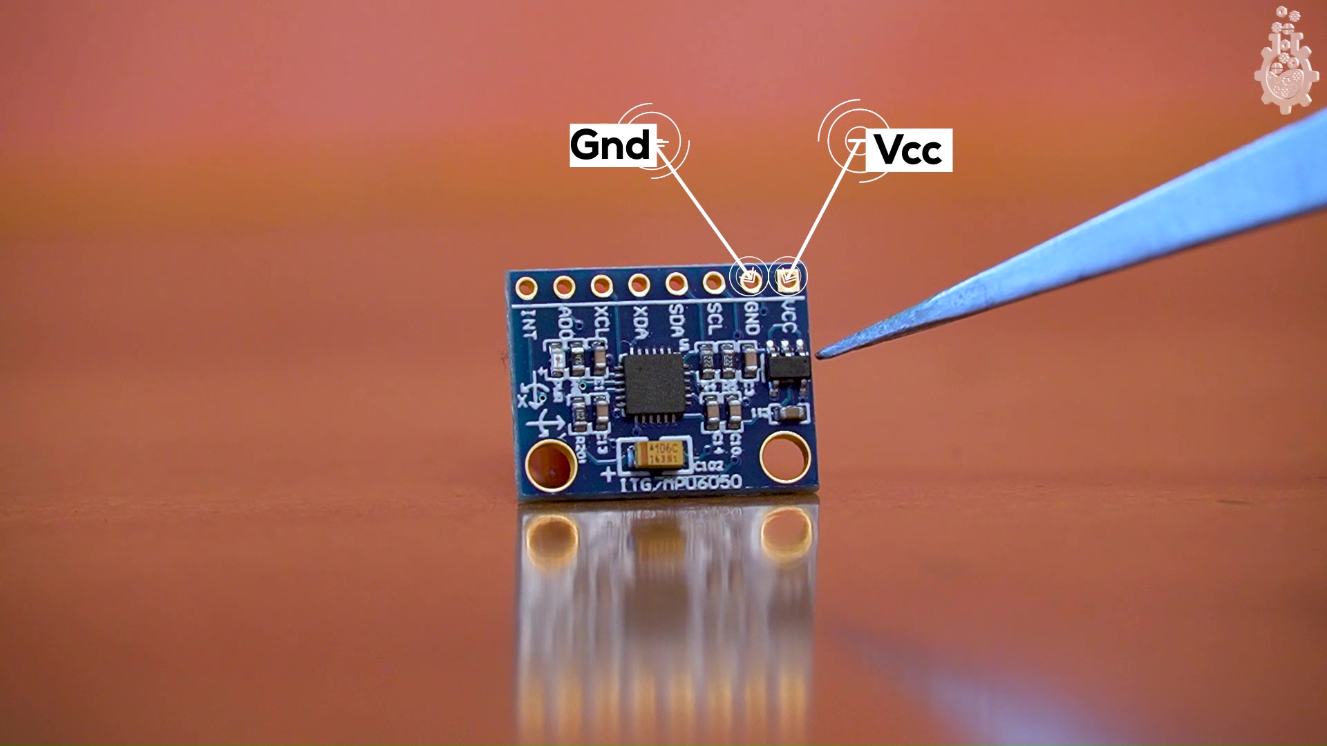
MPU 6050 comes in a Module form, with 8 pins, but don’t worry, we will use only 4 important pins and it will be sufficient to integrate with our Arduino Board.
So we have VCC, ground, which takes any input from 2v to 5v, since this board has a voltage regulator on board and thus supports 3.3v logic high and 5v logic high.
Next we have few complimentary resistors and capacitors in SMD package and the most important PART the MPU6050 IC, which is a MEMS or say micro electro mechanical system, which changes voltage depending on change in axis position.
This IC also has SCL SDA, which are I2C pins and XDA and XCL which are auxiliary Serial pins, we won’t use them with Arduino for this tutorial, we have AD0 which is address select between Auxiliary and Primary ports, lastly we have INT interrupt pin,
connections for our Arduino UNO and NANO are as following:
(only SDA and SCL pins change for other Arduino boards.)
Работа с Arduino и MPU6050
Arduino и датчик MPU6050
MPU6050 представляет собой 3-х осевой гироскоп и 3-х же осевой акселерометр в одном корпусе. Сразу поясню, что это и для чего:
- Гироскоп измеряет угловую скорость вращения вокруг оси, условно в градусах/секунду. Если датчик лежит на столе – по всем трём осям будет значение около нуля. Для нахождения текущего угла по скорости нужно интегрировать эту скорость. Гироскоп может чуть привирать, поэтому ориентироваться на него для расчёта текущего угла не получится даже при идеальной калибровке.
- Акселерометр измеряет ускорение вдоль оси, условно в метрах/секунду/секунду. Если датчик лежит на столе или движется с постоянной скоростью – на оси будет спроецирован вектор силы тяжести. Если датчик движется с ускорением – вдобавок к ускорению свободного падения получим составляющие вектора ускорения. Если датчик находится в свободном падении (в том числе на орбите планеты) – величины ускорений по всем осям будут равны 0. Зная проекции вектора силы тяжести можно с высокой точностью определить угол наклона датчика относительно него (привет, школьная математика). Если датчик движется – однозначно определить направление вектора силы тяжести не получится, соответственно угол тоже.
Модуль стоит в районе 150 рублей на нашем любимом AliExpress (ссылка, ссылка), а также входит в Arduino набор GyverKIT.
Итак, по отдельности акселерометр и гироскоп не могут обеспечить точное измерение угла, но вместе – ещё как могут! Об этом мы поговорим ниже. А начнём с подключения и базового общения с датчиком.
Подключение
Датчик подключается на шину i2c (SDA -> A4, SCL -> A5, GND -> GND). На плате стоит стабилизатор, позволяющий питаться от пина 5V (VCC -> 5V).
На модуле выведен пин AD0. Если он никуда не подключен (или подключен к GND) – адрес датчика на шине i2c будет 0x68, если подключен к питанию (VCC) – адрес будет 0x69. Таким образом без дополнительных микросхем можно подключить два датчика на шину с разными адресами.
Arduino and MPU6050 Accelerometer and Gyroscope Tutorial
In this tutorial we will learn how to use the MPU6050 Accelerometer and Gyroscope sensor with the Arduino. First, I will explain how the MPU6050 works and how to read the data from it, and then we will make two practical examples.
You can watch the following video or read the written tutorial below.
Overview
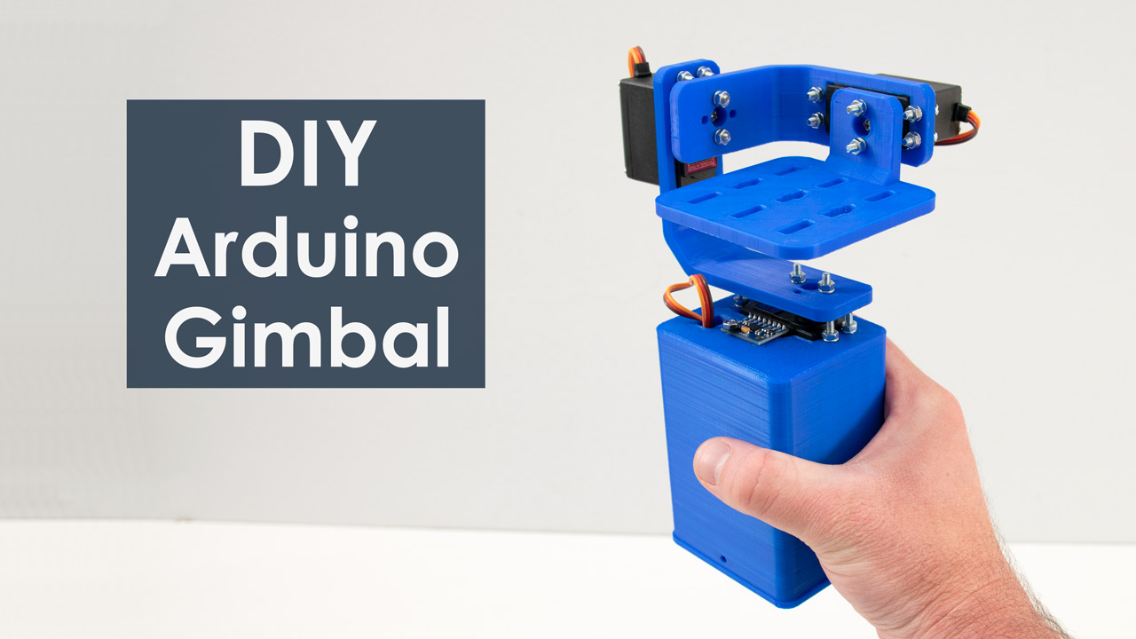
In the first example, using the Processing development environment, we will make a 3D visualization of the sensor orientation, and in the second example we will make a simple self-stabilizing platform or a DIY Gimbal. Based on the MPU6050 orientation and its fused accelerometer and gyroscope data, we control the three servos that keep the platform level.
How It Works
The MPU6050 IMU has both 3-Axis accelerometer and 3-Axis gyroscope integrated on a single chip.
The gyroscope measures rotational velocity or rate of change of the angular position over time, along the X, Y and Z axis. It uses MEMS technology and the Coriolis Effect for measuring, but for more details on it you can check my particular How MEMS Sensors Work tutorial. The outputs of the gyroscope are in degrees per second, so in order to get the angular position we just need to integrate the angular velocity.
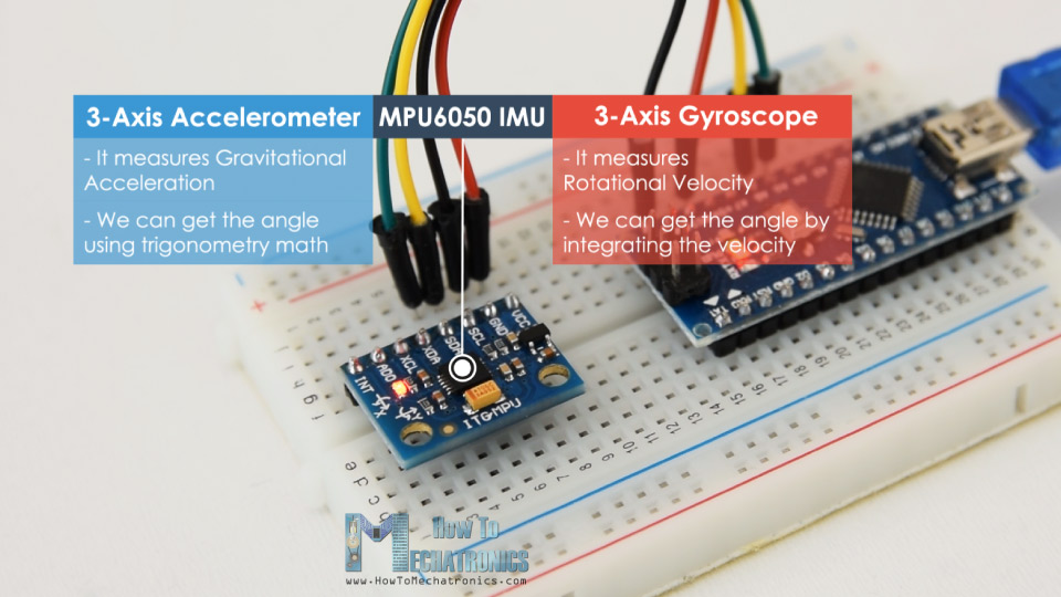
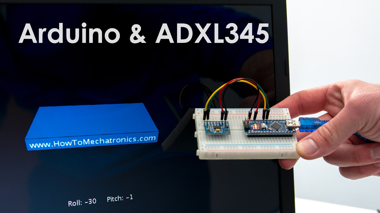
On the other hand, the MPU6050 accelerometer measures acceleration in the same way as explained in the previous video for the ADXL345 accelerometer sensor. Briefly, it can measure gravitational acceleration along the 3 axes and using some trigonometry math we can calculate the angle at which the sensor is positioned. So, if we fuse, or combine the accelerometer and gyroscope data we can get very accurate information about the sensor orientation.
The MPU6050 IMU is also called six-axis motion tracking device or 6 DoF (six Degrees of Freedom) device, because of its 6 outputs, or the 3 accelerometer outputs and the 3 gyroscope outputs.
Arduino and MPU6050
Let’s take a look how we can connect and read the data from the MPU6050 sensor using the Arduino. We are using the I2C protocol for communication with the Arduino so we need only two wires for connecting it, plus the two wires for powering.
You can get the components needed for this Arduino Tutorial from the links below:
Disclosure: These are affiliate links. As an Amazon Associate I earn from qualifying purchases.
MPU6050 Arduino Code
Here’s the Arduino code for reading the data from the MPU6050 sensor. Below the code you can find a detail description of it.
Code Description: So first we need to include the Wire.h library which is used for the I2C communication and define some variables needed storing the data.
In the setup section, we need initialize the wire library and reset the sensor through the power management register. In order to do that we need to take a look at the datasheet of the sensor from where we can see the register address.
Also, if we want, we can select the Full-Scale Range for the accelerometer and the gyroscope using their configuration registers. For this example, we will use the default +- 2g range for the accelerometer and 250 degrees/s range for the gyroscope, so I will leave this part of the code commented.
In the loop section we start by reading the accelerometer data. The data for each axis is stored in two bytes or registers and we can see the addresses of these registers from the datasheet of the sensor.
In order to read them all, we start with the first register, and using the requiestFrom() function we request to read all 6 registers for the X, Y and Z axes. Then we read the data from each register, and because the outputs are twos complement, we combine them appropriately to get the correct values.
In order to get output values from -1g to +1g, suitable for calculating the angles, we divide the output with the previously selected sensitivity.
Finally, using these two formulas, we calculate the roll and pitch angles from the accelerometer data.
Next, using the same method we get the gyroscope data.
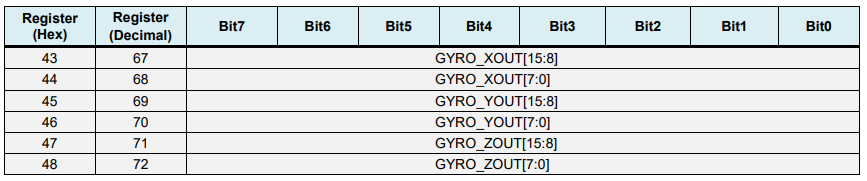
We read the six gyroscope registers, combine their data appropriately and divide it by the previously selected sensitivity in order to get the output in degrees per second.
Here you can notice that I correct the output values with some small calculated error values, which I will explain how we get them in a minute. So as the outputs are in degrees per second, now we need to multiply them with the time to get just degrees. The time value is captured before each reading iteration using the millis() function.
Finally, we fuse the accelerometer and the gyroscope data using a complementary filter. Here, we take 96% of the gyroscope data because it is very accurate and doesn’t suffer from external forces. The down side of the gyroscope is that it drifts, or it introduces error in the output as the time goes on. Therefore, on the long term, we use the data from the accelerometer, 4% in this case, enough to eliminate the gyroscope drift error.
However, as we cannot calculate the Yaw from the accelerometer data, we cannot implement the complementary filter on it.
Before we take a look at the results, let me quickly explain how to get the error correction values. For calculate these errors we can call the calculate_IMU_error() custom function while the sensor is in flat still position. Here we do 200 readings for all outputs, we sum them and divide them by 200. As we are holding the sensor in flat still position, the expected output values should be 0. So, with this calculation we can get the average error the sensor makes.
We simply print the values on the serial monitor and once we know them, we can implement them in the code as shown earlier, for both the roll and pitch calculation, as well as for the 3 gyroscope outputs.
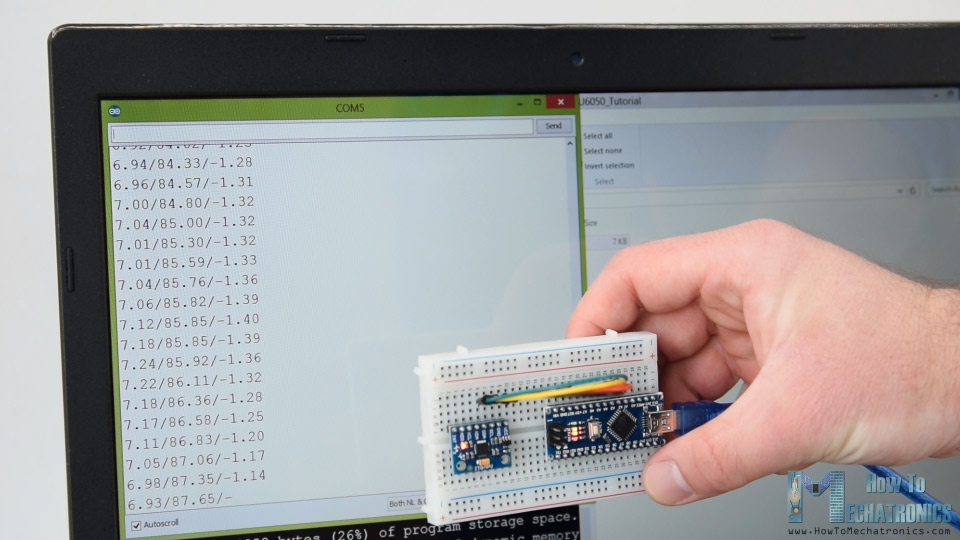
Finally, using the Serial.print function we can print the Roll, Pitch and Yaw values on the serial monitor and see whether the sensor works properly.
MPU6050 Orientation Tracking – 3D Visualization
Next, in order to make the 3D visualization example we just need accept this data the Arduino is sending through the serial port in the Processing development environment. Here’s the complete Processing code:
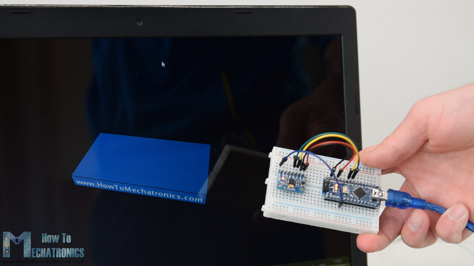
Here we read the incoming data from the Arduino and put it into the appropriate Roll, Pitch and Yaw variables. In the main draw loop, we use these values to rotate the 3D object, in this case that’s a simple box with a particular color and text on it.
If we run the sketch, we can see how good the MPU6050 sensor is for tracking orientation. The 3D object tracks the orientation of the sensor quite accurate and it’s also very responsive.
![]()
As I mentioned, the only down side is that the Yaw will drift over time because we cannot use the complementary filter for it. For improving this we need to use an additional sensor. That’s usually a magnetometer which can be used as a long-term correction for the gyroscope Yaw drift. However, the MPU6050 actually have a feature that’s called Digital Motion Processor which is used for onboard calculations of the data and it’s capable of eliminating the Yaw drift.
Here’s the same 3D example with the Digital Motion Processor in use. We can see how accurate the orientation tracking is now, without the Yaw drift. The onboard processor can also calculate and output Quaternions which are used for representing orientations and rotations of objects in three dimensions. In this example we are actually using quaternions for representing the orientation which also doesn’t suffer from Gimbal lock which occurs when using Euler angles.
Nevertheless, getting this data from the sensor is a bit more complicated than what we explained earlier. First of all, we need to connect and additional wire to an Arduino digital pin. That’s an interrupt pin which is used for reading this data type from the MPU6050.
The code is also a bit more complicated so that’s why we are going to use the i2cdevlib library by Jeff Rowberg. This library can be downloaded from GitHub and I will include a link to in on the website article.
Once we install the library, we can open the MPU6050_DMP6 example from the library. This example is well explained with comments for each line.
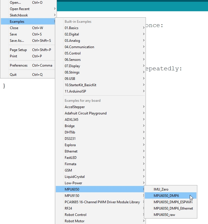
Here we can select what kind of output we want, quaternions, Euler angles, yaw, pitch and roll, accelerations value or quaternions for the 3D visualization. This library also includes a Processing sketch for the 3D visualization example. I just modified it to get the box shape as in the previous example. Here’s the 3D visualization Processing code that works with the MPU6050_DPM6 example, for selected “OUTPUT_TEAPOT” output:
So here using the serialEvent() function we receive the quaternions coming from the Arduino, and in the main draw loop we use them to rotate the 3D object. If we run the sketch, we can see how good quaternions are for rotating objects in three dimensions.
In order not to overload this tutorial, I placed the second example, the DIY Arduino Gimbal or Self-Stabilizing platform, on a separate article.
Feel free to ask any question related to this tutorial in the comments section below and also don’t forget to check my collection of Arduino Projects.