Круглый светодиодный модуль RGB WS2812 / 7×LED
Используйте круглые светодиодные модули WS2812 для создания динамичной подсветки.

Пример для Arduino
В качестве мозга для управления светодиодами WS2812 рассмотрим платформу Arduino Uno.
Схема подключения
Исходный код
Прошейте платформу Arduino скетчем приведённым ниже.
Пример для Espruino
В качестве мозга для управления светодиодами WS2812 рассмотрим платформу Iskra JS.
Схема подключения
Исходный код
Прошейте платформу Iskra JS скриптом приведённым ниже.
Элементы платы

Светодиод
На каждом кластере расположено по три светодиода SMD 5050 (5×5 мм). Светодиод — полупроводниковый источник света, предназначенный для конструирования в различных осветительных устройств. Светодиод стабилен при перепадах температуры и влажности, выдерживает длительное воздействие солнечных лучей и вибрации.
Чип светодиода SMD 5050 состоит из трёх кристаллов. Каждый кристалл имеет два отдельных вывода (анод и катод), что дает возможность для независимой регулировки их яркости. 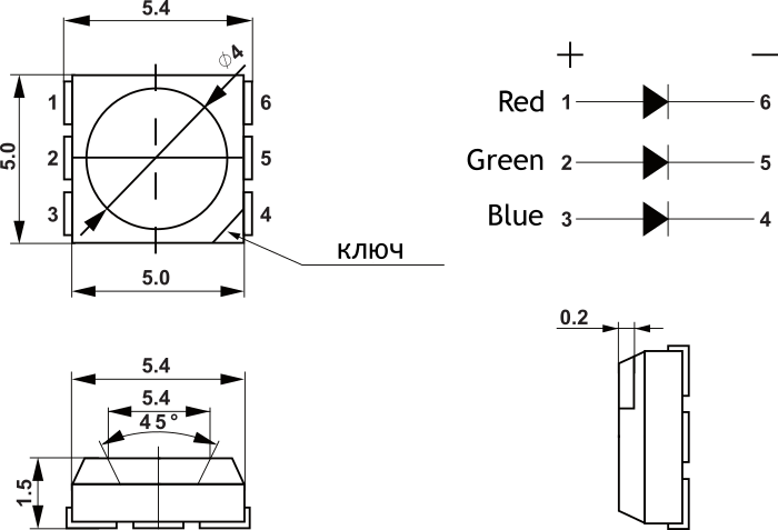
Светодиоды изготавливается в двух вариациях:
Многоцветные или RGB-светодиоды состоят из трёх кристаллов разных цветов: синего, красного и зелёного(Red, Green, Blue). Изменяя ток одного, двух или трёх кристаллов одновременно, можно получить практически любой цвет излучения из видимого спектра.
Arduino Lesson 1. Blink
Overview
New Subscription
Please sign in to subscribe to this guide.
You will be redirected back to this guide once you sign in, and can then subscribe to this guide.

Parts


The ‘L’ LED
The Arduino has rows of connectors along both sides that are used to connect to electronic devices and plug-in ‘shields’ that allow the Arduino to do more.
However, the Arduino also has a single LED that you can control from your sketches. This LED is built onto the Arduino board and is often referred to as the ‘L’ LED as this is how it is labelled on the board.
The position of this LED is circled in red on the pictures of the Arduino Uno and Leonardo below.


Loading the ‘Blink’ Example
You may find that your Arduino board’s ‘L’ LED already blinks when you connect it to a USB plug. This is because Arduino boards are generally shipped with the ‘Blink’ sketch pre-installed.
In this lesson, we will reprogram the Arduino with our own Blink sketch and then change the rate at which it blinks.
In Lesson 0, you setup your Arduino IDE and made sure that you could find the right serial port for it to connect to your Arduino board. The time has now come to put that connection to the test and program your Arduino board.
The Arduino IDE includes a large collection of example sketches that you can load up and use. This includes an example sketch for making the ‘L’ LED blink.
Load the ‘Blink’ sketch that you will find in the IDE’s menu system under File → Examples → 01.Basics


Saving a Copy of ‘Blink’
The example sketches included with the Arduino IDE are ‘read-only’. That is, you can upload them to an Arduino board, but if you change them, you cannot save them as the same file.
We are going to change this sketch, so, the first thing you need to do is save your own copy that you can change however you like.
From the File menu on the Arduino IDE select the option ‘Save As..’ and then save the sketch with the name ‘MyBlink’.


Uploading Blink to the Board
Attach your Arduino board to your computer with the USB cable and check that the ‘Board Type’ and ‘Serial Port’ are set correctly. You may need to refer back to Lesson 0.
The Arduino IDE will show you the current settings for board at the bottom of the window.


The clue is at the top here, it probably means that your board is not connected at all, or the drivers have not been installed (if necessary) or that the wrong serial port is selected.
If you get this, go back to Lesson 0 and check your installation.
Once the upload has completed, the board should restart and start blinking.
How ‘Blink’ Works
The first thing to note is that quite a lot of this sketch is what is called ‘comments’. Comments are not actual program instructions, they are just comments about how the program works. They are there for out benefit, so that there is some explanation to accompany the sketch.
Everything between /* and */ at the top of the sketch is a block comment, that explains what the sketch is for.
There are also single line comments that start with // and everything up intil the end of the line counts as being a comment.
The first actual line of code is:
Every Arduino sketch must have a ‘setup’ function, and the part of it where you might want to add instructions of your own is between the < and the >.
In this case, there is just one command there, which, as the comment states tells the Arduino board that we are going to use the LED pin as an output.
It is also mandatory for a sketch to have a ‘loop’ function. Unlike the ‘setup’ function that only runs once, after a reset, the ‘loop’ function will, after it has finished running its commands, immediately start again.