Display Custom Bitmap graphics on an Arduino Touch Screen and other Arduino compatible Displays
Displaying a custom image or graphic on a LCD display is a very useful task as displays are now a premium way of providing feedback to users on any project. With this functionality, we can build projects that display our own logo, or display images that help users better understand a particular task the project is performing, providing an all-round improved User Experience (UX) for your Arduino or ESP8266 based project. Today’s tutorial will focus on how you can display graphics on most Arduino compatible displays.
The procedure described in this tutorial works with all color displays supported by Adafruit’s GFX library and also works for displays supported by the TFTLCD library from Adafruit with little modification. Some of the displays on which this procedure works include:
While these are the displays we have, and on which this tutorial was tested, we are confident it will work perfectly fine with most of the other Arduino compatible displays.
For each of the displays mentioned above, we have covered in past how to program and connect them to Arduino. You should check those tutorials, as they will give you the necessary background knowledge on how each of these displays works.
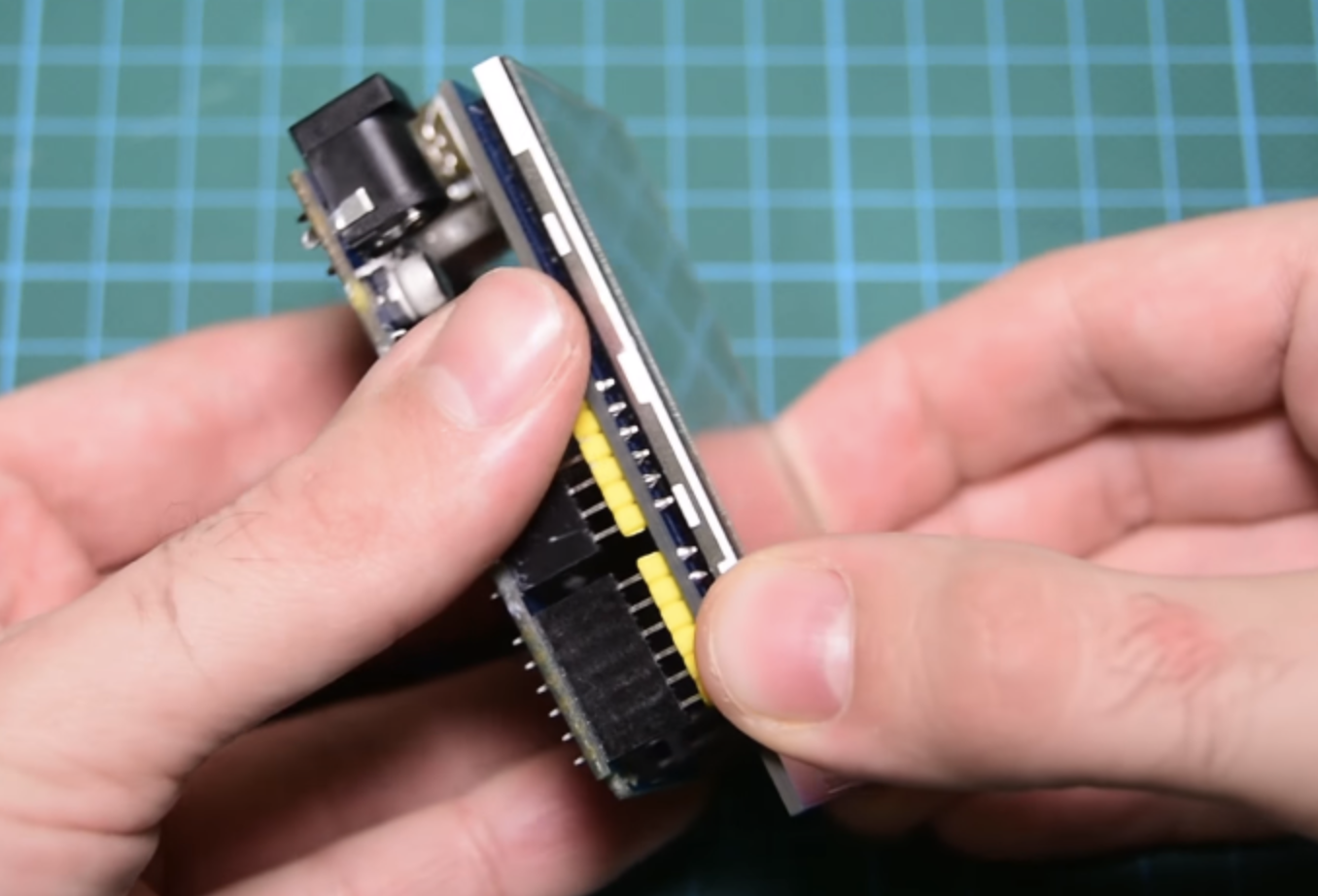
For this tutorial, we will use the 2.8″ ILI9325 TFT Display which offers a resolution of 320 x 340 pixels and we will display a bitmap image of a car.
 2.8″ ILI9325 TFT Display
Required Components
To demonstrate how this works with different displays, you can use some of the most popular displays:
As usual, each of the components listed above can be bought from the links attached to them. While having all of the displays listed above may be useful, you can use just one of them for this tutorial.
Schematics
To demonstrate how things work, we will use the 2.8″ TFT Display. The 2.8″ TFT display comes as a shield which plugs directly into the Arduino UNO as shown in the image below.
 Connect the Display to the Arduino
Not all Arduino displays are available as shields, so when working with any of them, connect the display as you would when displaying text (we recommend following the detailed tutorial for the display type you use of the above list). This means no special connection is required to display graphics.
With the screen connected, we then proceed to prepare the graphics images to be displayed.
Preparing the Graphics
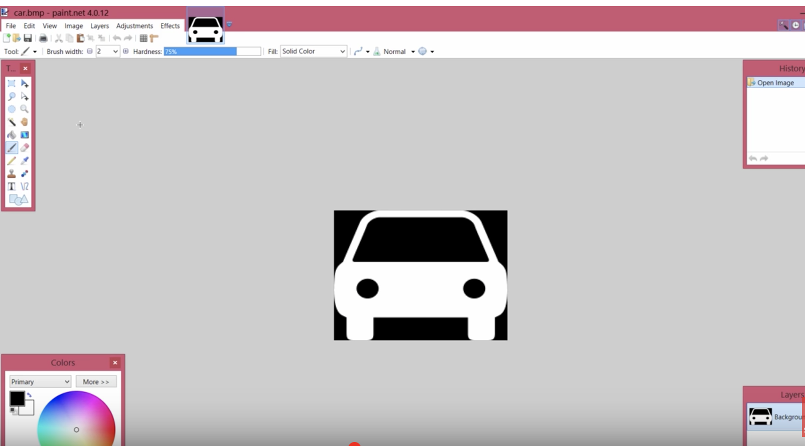
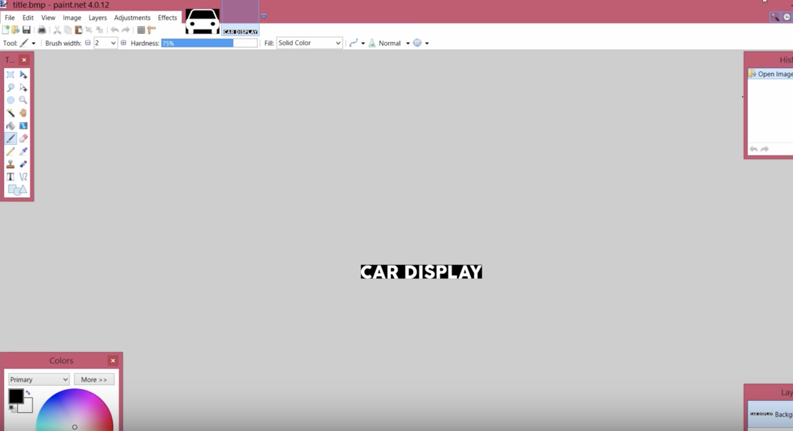
Before an image is displayed on any of the Arduino screens, it needs to be converted to a C compatible hex file and that can only happen when the image is in bitmap form. Thus, our first task is to create a bitmap version of the graphics to be displayed or convert the existing image to a bitmap file. There are several tools that can be used for creation/conversion of bitmap images including, Corel Draw and Paint.net, but for this tutorial, we will use the Paint.net.
Our demo graphics today will be a car. We will create the car on a black background and use a white fill so it’s easy for us to change the color later on.
 Using Paint.Net
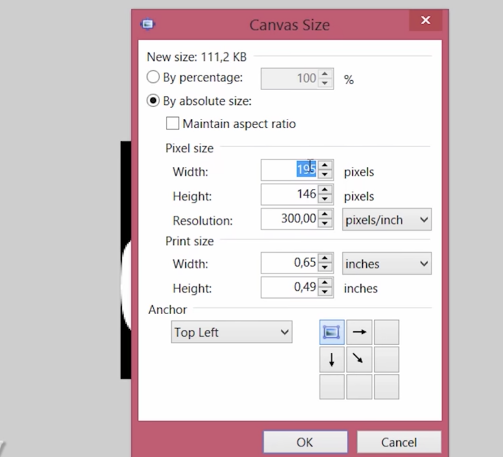
The resolution of the graphics created should be smaller than the resolution of your display to ensure the graphics fit properly on the display. For this example, the resolution of the display is 320 x 340, thus the resolution of the graphics was set to 195 x 146 pixels.
 Set the Resolution to Match Your Display
Your graphics could also include some text. Just ensure the background is black and the fill color is white if you plan to change the color within your Arduino code.
 Displaying graphical Text
With the graphics done, save both files as .bmp with 24bits color. It is important to keep in mind that large bitmaps use up a lot of memory and may prevent your code from running properly so always keep the bitmaps as small as possible.
The next task is to convert the graphics into byte arrays so they can be used in the code.
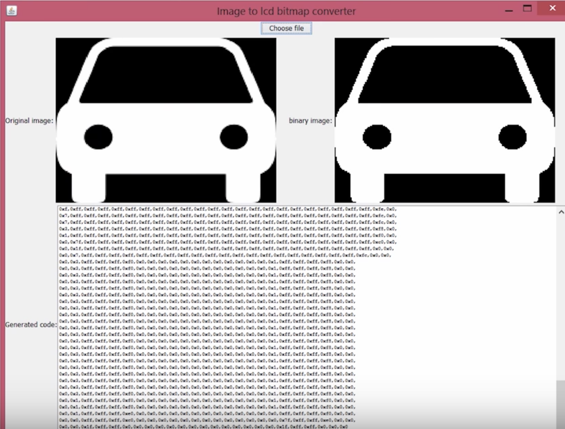
To do this, we will use the “Image2Code” Java utility developed by Adafruit.
Image2Code is an easy-to-use, small Java utility to convert images into a byte array that can be used as a bitmap on displays that are compatible with the Adafruit-GFX or Adafruit TFTLCD (with little modification) library.
All we have to do is to load the graphics into the software by clicking the “Choose file” button and it will automatically generate a byte array equivalent to the selected bitmap file.
 Conversion from Image to Data
Copy the generated bit array, and create a graphics.c file in the same Arduino project folder where the code will reside.
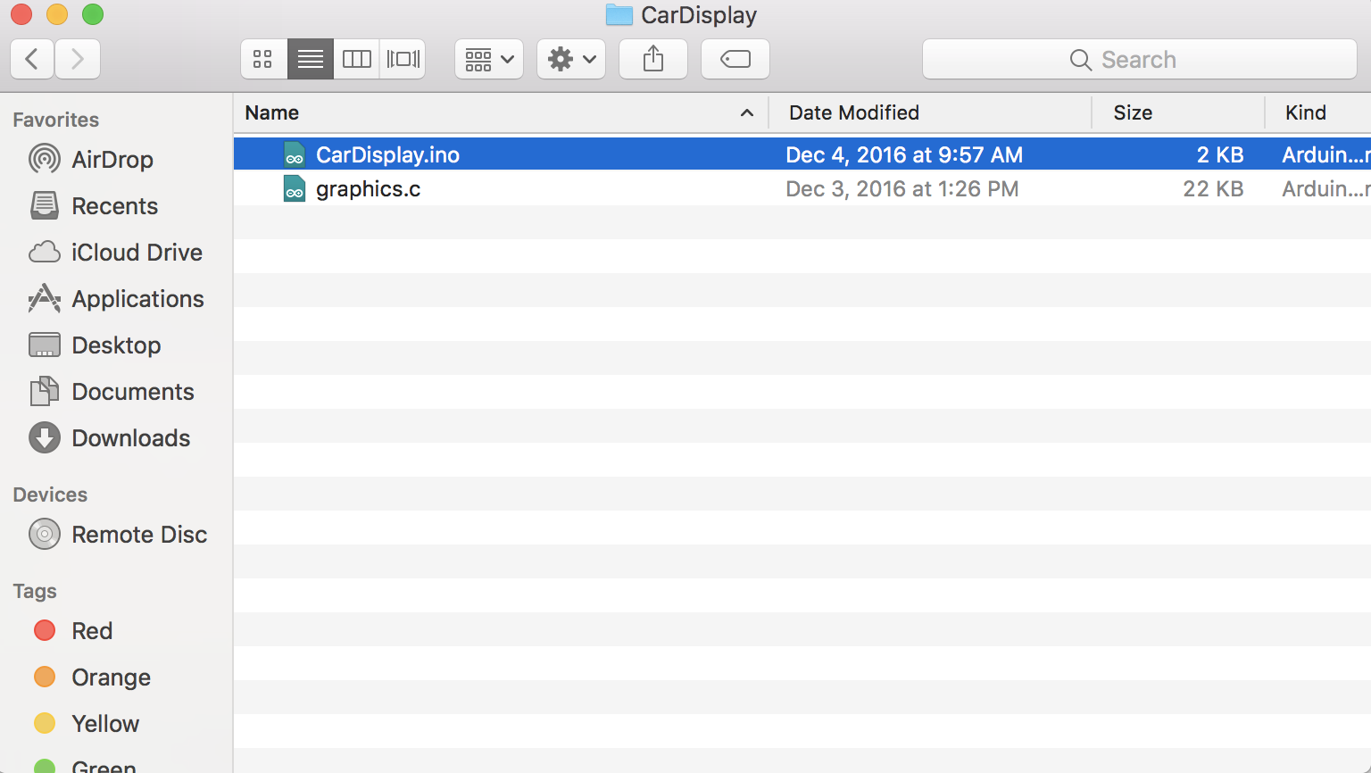 Ensure the File is in the Same Directory as your main code
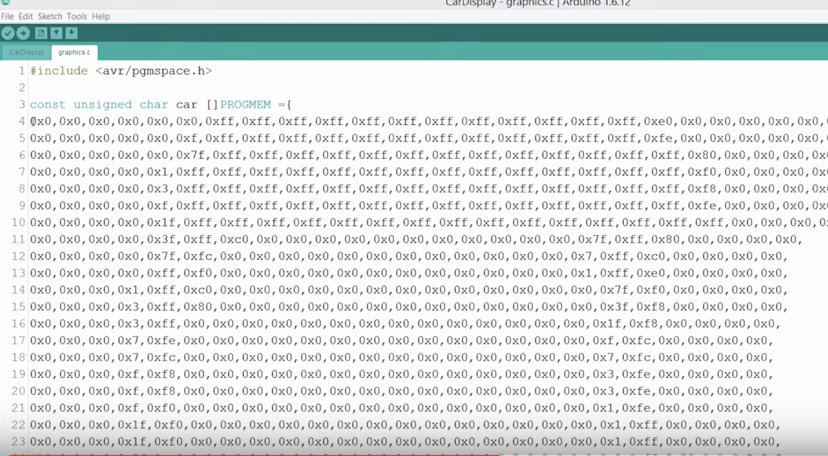
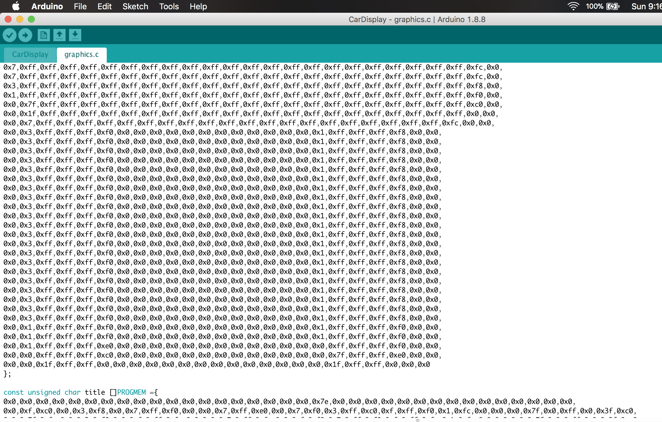
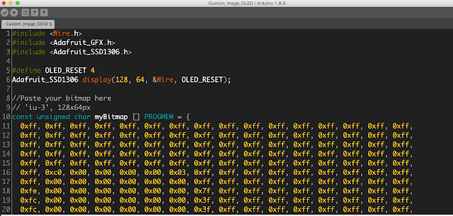
Paste the bit array in the graphics.c file and save. Since we have two graphics (the car and the text), You can paste their data array in the same file. check the graphics.c file attached to the zip file, under the download section to understand how to do this. Don’t forget to declare the data type as “const unsigned char“, add PROGEM in front of it and include the avr/pgmspace.h header file as shown in the image below. This instructs the code to store the graphics data in the program memory of the Arduino.
 Copying the Hex file to the Arduino IDE
With this done, we are now ready to write the code. Do note that this procedure is the same for all kind of displays and all kind of graphics. Convert the graphics to a bitmap file and use the Img2code utility to convert it into a hex file which can then be used in your Arduino code.
To reduce the amount of code, and stress involved in displaying the graphics, we will use two wonderful libraries; The GFX library and the TFTLCD library from Adafruit.
The GFX library, among several other useful functions, has a function called drawBitmap(), which enables the display of a monochrome bitmap image on the display. This function allows the upload of monochrome only (single color) graphics, but this can be overcome by changing the color of the bitmap using some code.
The Adafruit libraries do not support all of the displays but there are several modifications of the libraries on the internet for more displays. If you are unable to find a modified version of the library suitable for your the display, all you need do is copy the code of the drawBitmap() function from the GFX library and paste it in the Arduino sketch for your project such that it becomes a user-defined function.
The drawBitmap function takes 6 arguments as shown in the code snippet below;
The first two are the x and y coordinates of a point on the screen where we want the image to be displayed. The next argument is the array in which the bitmap is loaded in our code, in this case, it will be the name of the car and the text array located in the graphics.c file. The next two arguments are the width and height of the bitmap in pixels, in other words, the resolution of the image. The last argument is the color of the bitmap, we can use any color we like. The bitmap data must be located in program memory since Arduino has a limited amount of RAM memory available.
Since using a display without the GFX library is more complex, it’s probably better to do an explanation of how to write the code for this procedure.
As usual, we start writing the sketch by including the libraries required. For this procedure, we will use the TFTLCD library alone, since we are assuming you are using a display that is not supported by the GFX library.
Next, we declare the pins of the Arduino to which the LCD is connected.
Next, we create the colors to be used, specifying the matching hex values and then create an instance of the TFTLCD library.
Next, we specify the name of the graphics to be displayed; car and title. At this stage, you should have added the bit array for these two bitmaps in the graphics.c file and the file should be placed in the same folder as the Arduino sketch.
Next, we write the void setup function. All we do here is to initialize the screen and rotate it to a preferred orientation.
With that done, we proceed to the void loop function, under the loop function, we call the drawbitmap() function to display the car and the text bitmap using different colors.
The last section of the code is the drawBitmap function itself, as earlier mentioned, to use the drawbitmap() function with the Adafruit TFTLCD library, we need to copy the function’s code and paste into the Arduino sketch.
The complete code for the project is available below and also attached under the download section at the end of the tutorial.
Plug in your screen as shown above. If you are using any other display, connect it as shown in the corresponding linked tutorial. With the schematics in place, connect the Arduino board to your PC and upload the code. Don’t forget the graphics file needs to be in the same folder as the Arduino sketch.
With that done, you should see your screen come up as shown in the image below.
That’s it for this tutorial guys. The procedure is the same for all kinds of Arduino compatible displays. If you get stuck while trying to replicate this using any other display, feel free to reach out to me via the comment sections below.
The video version of this tutorial is available on Youtube.
FoxExe/Image2Bitmap
Use Git or checkout with SVN using the web URL.
Work fast with our official CLI. Learn more.
Launching GitHub Desktop
If nothing happens, download GitHub Desktop and try again.
Launching GitHub Desktop
If nothing happens, download GitHub Desktop and try again.
Launching Xcode
If nothing happens, download Xcode and try again.
Launching Visual Studio Code
Your codespace will open once ready.
There was a problem preparing your codespace, please try again.
Latest commit
Git stats
Files
Failed to load latest commit information.
README.md
Image to byte array (bitmap) converter. Usable for Arduino, STM32, ESP8266, RaspberryPI, OrangePI and other controllers with small LCD screens like PCD8544, SSD1306 and others.

Supported conversion formats:
- Monochrome, 8 pixels/byte, Horisontal byte compression
- Monochrome, 8 pixels/byte, Vertical byte compression (PCD8544 / Nokia 3310/5110 LCD)
- Color, RGB332 (8 bit: RRRGGGBB, 256 colors)
- Color, RGB444 (16bit: —-RRRRGGGGBBBB, 4096 colors)
- Color, RGB565 (16bit: RRRRRGGGGGGBBBBB, 65536 colors)
- Two-way conversion (Image-to-byteArray and byteArray-to-Image)
- Zoom/crop preview
- More formats?
- Howto, About, Contacts and other info
About
Image to bit array converter (For Arduino and others)
Interfacing and Displaying Images on OLED © GPL3+
Interfacing an OLED 128×64 display with Arduino UNO and displaying images.
In this tutorial, we are going to learn to interface Arduino UNO with OLED 128×64 I2C monochrome display and display images.
Connect the pins of OLED with the following pins of Arduino UNO, as shown below.
Arduino UNO OLED
Install Required Libraries
- Adafruit_GFX.h https://github.com/adafruit/Adafruit-GFX-Library
- Adafruit_SSD1306.h https://www.github.com/adafruit/Adafruit_SSD1306
- Wire.h this library will be installed by default
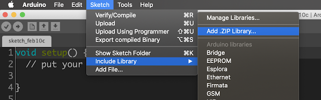
Either you can download the libraries from Github and add the ZIP file in Arduino IDE using add.zip library option.
Or you can install the libraries directly from Arduino IDE from Manage Libraries.
Follow the below steps to install.
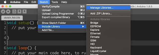
Open manage library from sketch -> include library -> manage libraries
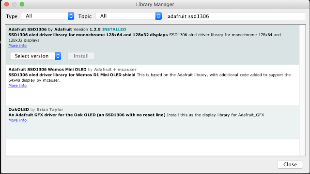
Then Search for AdafruitSSD1306 and click on the install button.
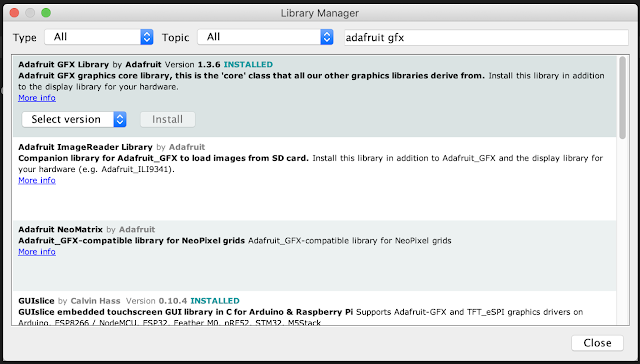
Then Search for the AdafruitGFX and click the install button. Now we have successfully installed the required libraries for this project.
Adafruit Example Code
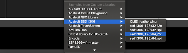
Let’s upload the adafruitSSD1306 library example program and test our setup.Open the example program from File -> Examples -> Adafruit SSD1306 -> ssd1306_128x64_i2c, because We are using OLED display with I2C interface with the screen size of 128×64.
Now Let’s Upload the Code
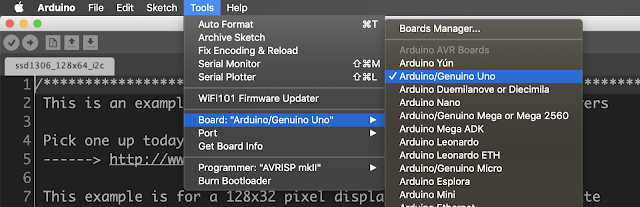
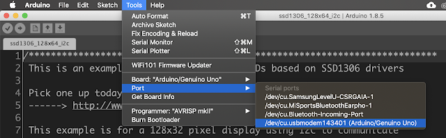
Go to tool menu -> Boards select Arduino UNO, then from Port select the port to which the Arduino is connected
Displaying Images on OLED
To display an image on OLED display first We need to convert the image to HEX code, for that purpose We need to use a converter like image2cpp by javl Image2cpp
Converting Image to Bitmap HEX Code
Step 1: Open Converter
Click on the image2cpp button and open the application in a new tab.
Step 2: Choose Image File
Click on choose files and choose the image file which you need to display in the OLED.

Step 3: Image Settings
Below is the screenshot of the default settings when We open the facebook logo.
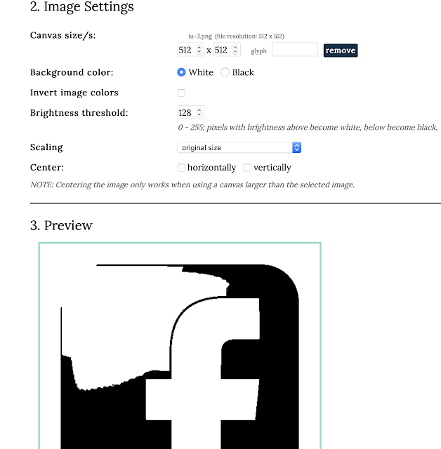
Here We need to change at least the canvas size, scaling, and brightness threshold to get a proper output in our OLED display.
Canvas Size: it is the size of our OLED display in my case its 128×64 is you are using any other OLED display then change the settings accordingly
Brightness Threshold: It is for adjusting the intensity with respect to the background, You can understand it correctly with using the application.
Scaling: It is for adjusting the image size with respect to the Canvas Size.
Below is the screenshot after updating the settings.
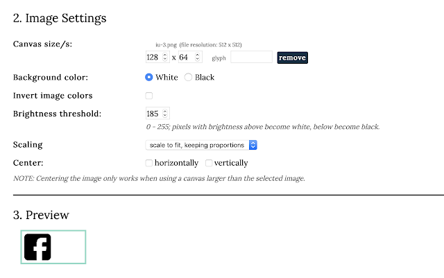
Now We got our nice looking facebook logo, I have to change the canvas size to «128 x 64», brightness threshold to «185», scaling to «scale to fit, keeping proportion». The other settings like center, background color and invert image colors are for tweaking, play with it to understand :).
Step 4: Generate Code
From code output, formate dropdown menu selects the Arduino code and click on the Generate code button.
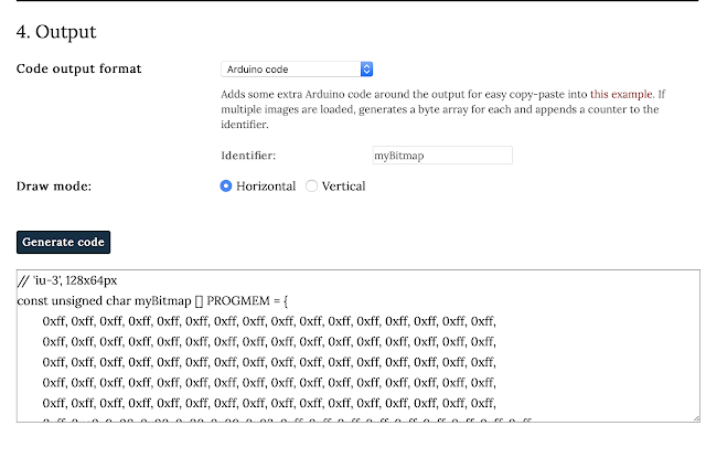
Now We have successfully generated the HEX code for our image, Let’s move to Arduino coding.
Copy the code below to a new Arduino sketch, then copy the above-generated HEX code just above the void Setup() function in the Arduino code.so it will look like this.
Now select the board and port from the tools menu and upload the code, that’s it now Our OLED will start displaying the image.