Digitrode
цифровая электроника вычислительная техника встраиваемые системы

ESP32 и часы реального времени DS3231
В этом уроке мы узнаем о работе часов реального времени (RTC) и их взаимодействии с ESP32 и дисплеем OLED.

Мы будем использовать модуль DS3231 RTC, чтобы отслеживать правильное время и отображать его на OLED дисплее, используя ESP32 в качестве нашего микроконтроллера. ESP32 – это больше, чем микроконтроллер. Он имеет функции Wi-Fi и Bluetooth и 39 контактов GPIO. Также он поддерживает все протоколы связи, такие как SPI, I2C, UART и т. д.
DS3231 – это модуль часов реального времени. Он используется для поддержания актуальной даты и времени для большинства проектов в области электроники. Этот модуль имеет собственный источник питания типа батирейка-таблетка, с помощью которого он поддерживает дату и время, даже когда основное питание отключено или микроконтроллер прошел полный сброс. Поэтому, как только мы установим дату и время в этом модуле, он всегда будет поддерживать их. Существует несколько типов микросхем RTC, таких как DS1307, DS3231 и т. д.

Для вывода даты и времени будем использовать OLED дисплей. Термин OLED обозначает «Органический светоизлучающий диод», он использует ту же технологию, которая используется в большинстве наших телевизоров, но имеет меньше пикселей по сравнению с ними.


Мы используем монохромный 7-контактный OLED-дисплей SSD1306 0,96”. Причина выбора этого дисплея заключается в том, что он может работать с тремя различными протоколами связи, такими как трехпроводной режим SPI 3, четырехпроводной режим SPI и I2C. В этом руководстве будет рассказано, как использовать модуль в 4-проводном режиме SPI, так как это самый быстрый и стандартный режим связи.
Сообщество Arduino уже предоставило нам много библиотек, которые можно напрямую использовать с ESP32. Например, библиотека Adafruit_SSD1306 очень проста в использовании и имеет несколько графических опций, поэтому мы будем использовать ее в этом руководстве. Но если у вашего проекта есть ограничение памяти/скорости, попробуйте использовать библиотеку U8g, поскольку она работает быстрее и занимает меньше памяти.
Принципиальная схема подключения модуля RTC3231 на основе DS3231 и OLED-дисплея SSD1306 к ESP32 представлена далее.

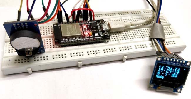
Физически все это может выглядеть следующим образом.

Код программы часов реального времени на ESP32 и DS3231 приведен далее.
Часы реального времени на ESP32 и модуле DS3231
В данной статье мы рассмотрим создание часов на основе микроконтроллера ESP32 и модуля часов реального времени DS3231. Информация о времени будет выводиться на экран OLED дисплея.

ESP32 – это больше чем обычный микроконтроллер. Он имеет встроенные чипы для Wi-Fi и Bluetooth связи, а также 39 контактов ввода/вывода (GPIO). Также он поддерживает множество протоколов связи: SPI, I2C, UART и т.д. Если вы только начинаете свое знакомство с модулем/микроконтроллером ESP32, то советуем прочитать руководство по началу работы с ним.
Необходимые компоненты
- Модуль ESP32 (купить на AliExpress).
- Модуль часов реального времени DS3231 (купить на AliExpress).
- Модуль OLED дисплея (SSD1306) 128×64 с 7-ю контактами (купить на AliExpress).
- Макетная плата.
- Соединительные провода.
Вместо модуля ESP32 в данном проекте можно также использовать плату NodeMCU ESP8266.
Что такое модуль DS3231
DS3231 – это модуль часов реального времени (Real Time Clock, RTC). Он используется для хранения информации о времени и дате во множестве электронных устройств во всем мире. В своем составе он имеет собственную батарейку, поэтому он сохраняет информацию о времени и дате даже когда питание основного устройства (в которое он входит) отключается или когда производится сброс устройства (микроконтроллера). То есть если мы один раз установим дату и время в модуле он будет хранить их постоянно, до тех пор пока не истощится его батарейка. В настоящее время существует несколько различных микросхем реального времени: DS1307, DS3231 и т.д.
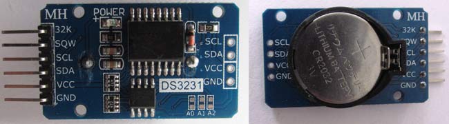
Внешний вид модуля DS3231 показан на следующем рисунке.

Ранее на нашем сайте мы рассматривали применение модуля DS3231 в следующих проектах:
Примечание : в данном проекте вместо модуля DS3231 можно также использовать модуль DS1307, на нашем сайте мы рассматривали его подключение к плате Arduino.
Общие сведения об OLED дисплеях
Технология OLED (Organic Light emitting diode – органический светоизлучающий диод) в настоящее время является самой распространённой для создания различных дисплеев, которые используются в современных телевизорах, ноутбуках, смартфонах и т.д. Небольшие по размеру OLED дисплеи находят применение и в различных электронных проектах – по сравнению с обычными алфавитно-цифровыми ЖК дисплеями они обеспечивают более наглядное отображение информации.
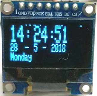
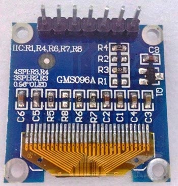
Внешний вид модуля OLED дисплея с 7-ю контактами показан на следующем рисунке.
 |  |
В нашем проекте мы будем использовать 7-контактый модуль OLED дисплея SSD1306 0.96”. Данный модуль поддерживает 3 режима связи с ним: 3-х проводный SPI, 4-х проводный SPI и IIC. Мы будем использовать интерфейс SPI с 4-мя проводами – он обеспечивает самую быструю передачу информации среди рассмотренных.
Назначение контактов данного дисплея приведено в следующей таблице.
| Номер контакта | Название контакта | Альтернативное название контакта | Назначение контакта |
| 1 | Gnd | Ground | земля |
| 2 | Vdd | Vcc, 5V | напряжение питания (в диапазоне 3-5 В) |
| 3 | SCK | D0, SCL, CLK | контакт синхронизации (clock pin). Применяется в интерфейсах I2C и SPI |
| 4 | SDA | D1, MOSI | контакт данных. Применяется в интерфейсах I2C и SPI |
| 5 | RES | RST, RESET | контакт сброса модуля. Применяется в интерфейсе SPI |
| 6 | DC | A0 | контакт команд (Data Command pin). Применяется в интерфейсе SPI |
| 7 | CS | Chip Select (выбор чипа) | используется когда несколько устройств взаимодействуют по интерфейсу SPI |
В данном проекте для взаимодействия с OLED дисплеем мы будем использовать библиотеку Adafruit_SSD1306 – она проста в использовании и обеспечивает много возможностей по работе с графикой. Но если ваш проект имеет жесткие ограничения по используемой памяти/быстродействию, то рекомендуем использовать библиотеку U8g – она работает быстрее и использует значительно меньше памяти.
Ранее на нашем сайте мы рассматривали подключение OLED дисплея к платам Arduino и Raspberry Pi, а также к модулю ESP8266.
Схема проекта
Схема часов реального времени на ESP32 и модуле DS3231 представлена на следующем рисунке.
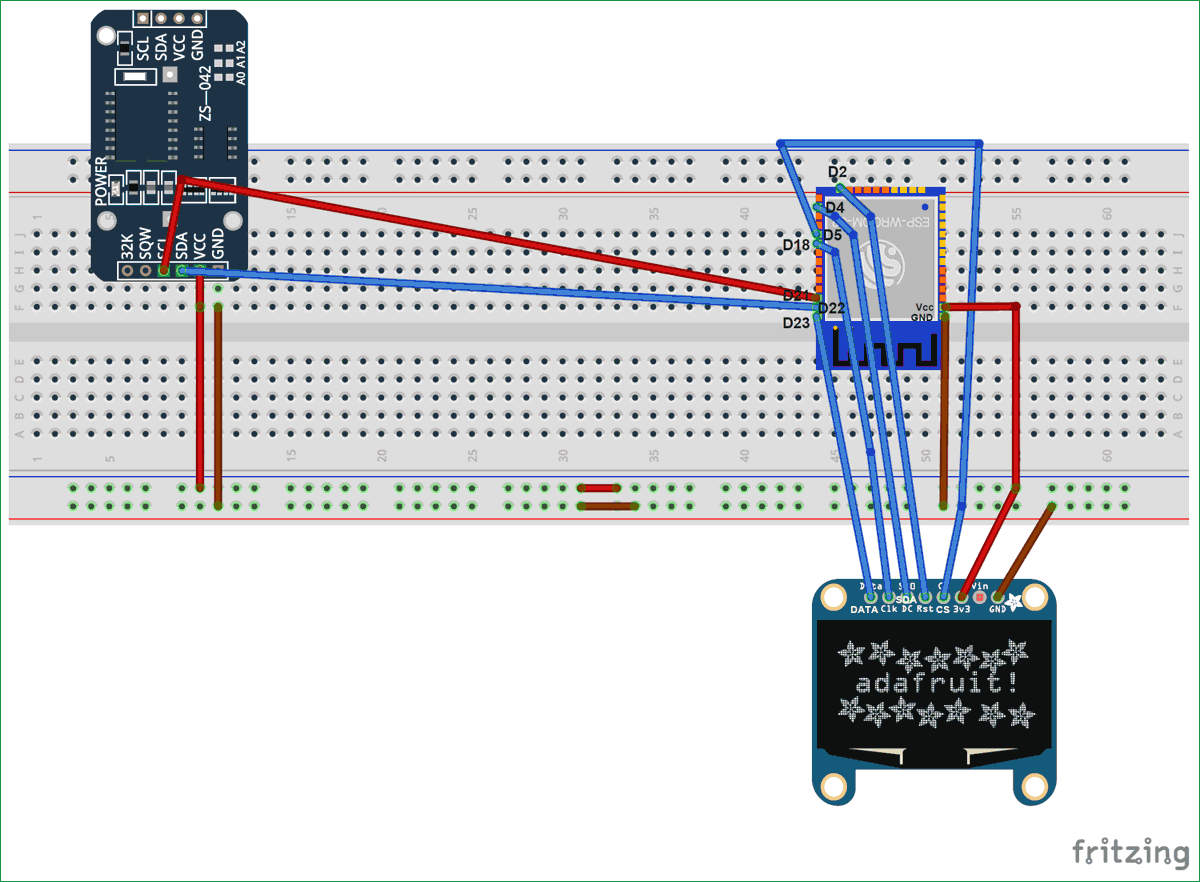
Микросхема модуля часов реального времени DS3231 использует для взаимодействия с другими устройствами протокол I2C по контактам SCL, SDA, Vcc и GND. Необходимо сделать следующие ее соединения с модулем ESP32:
- SCL of RTC -> SCL of ESP32 (Pin D22)
- SDA of RTC -> SDA of ESP32 (Pin D21)
- GND of RTC -> GND of ESP32
- Vcc of RTC -> Vcc of ESP32
В нашем проекте мы используем протокол SPI для взаимодействия между модулем ESP32 и OLED дисплеем. В схеме необходимо сделать следующие соединения между ними:
- CS (Chip select) pin of OLED -> PIN D5 модуля ESP32
- DC pin of OLED -> PIN D4 модуля ESP32
- RES pin of OLED -> PIN D2 модуля ESP32
- SDA pin of OLED -> PIN D23 (MOSI) модуля ESP32
- SCK pin of OLED -> PIN D18 (SCK) модуля ESP32
- Vdd of OLED -> Vcc модуля ESP32
- GND of OLED -> GND модуля ESP32
Внешний вид собранной на макетной плате конструкции проекта показан на следующем рисунке.
Объяснение программы для модуля ESP32
Полный код программы приведен в конце статьи, здесь же мы кратко рассмотрим его основные фрагменты.
Для данного проекта нам понадобится ряд библиотек, скачать которые можно по следующим ссылкам:
Далее в коде программы подключим эти библиотеки.
ESP32 Real Time Clock using DS3231 Module
In this tutorial, we will learn about Real Time Clock (RTC) and its interfacing with the ESP32 and OLED display.
We will use DS3231 RTC module to keep track of the correct time and display it on SPI OLED by using ESP32 as our microcontroller. ESP32 is more than a microcontroller. It has Wi-Fi and Bluetooth chip inside it and 39 GPIO pins. It supports all communication protocols like SPI, I2C, UART, etc. If you are new to ESP32 then first go through our Getting started with ESP32 tutorial.
What is RTC??
DS3231 is a RTC (Real Time Clock) module. It is used to maintain the date and time for most of the Electronics projects. This module has its own coin cell power supply using which it maintains the date and time even when the main power is removed or the MCU has gone through a hard reset. So once we set the date and time in this module it will keep track of it always. There are several types of RTC ICs available like DS1307, DS3231 etc.
We have previously used DS3231 RTC with Arduino in below projects:
Note: When using this module for the first time you have to set the date and time. You can also use RTC IC DS1307, we have previously used DS1307 with Arduino.
Getting to know about OLED Displays:
The term OLED stands for “Organic Light emitting diode” it uses the same technology that is used in most of our televisions but has fewer pixels compared to them. It is real fun to have these cool looking display modules since it will make our projects look cool. We have covered a full Article on OLED displays and its types here.
We are using a Monochrome 7-pin SSD1306 0.96” OLED display. The reason for choosing this display is that it can work on three different communications Protocols such as the SPI 3 Wire mode, SPI four wire mode and IIC mode. This tutorial will cover how to use the module in SPI 4-wire mode as it is the fastest mode of communication and the default one.
The pins and its functions are explained in the table below.
Pin Number
Pin Name
Other Names
Usage
1
Ground pin of the module
2
Power pin (3-5V tolerable)
3
Acts as the clock pin. Used for both I2C and SPI
4
Data pin of the module. Used for both IIC and SPI
5
Resets the module (useful during SPI)
6
Data Command pin. Used for SPI protocol
7
Useful when more than one module is used under SPI protocol
In this tutorial we will simply operate the module in 4-Wire SPI mode, we will leave the rest for some other tutorial.
Arduino community has already given us a lot of Libraries which can be directly used to make this a lot simpler. I tried out a few libraries and found that the Adafruit_SSD1306 Library was very easy to use and had a handful of graphical options hence we will use the same in this tutorial. But, if your project has a memory/speed constraint try using the U8g Library as it works faster and occupies less program memory.
Material Required:
- ESP32
- DS3231 RTC module
- 7 pin 128×64 OLED display Module (SSD1306)
- Male-female wires
- Breadboard
Circuit Diagram:
Circuit diagram to connect RTC3231 to ESP board is given below:

RTC DS3231 IC uses I2C mode of communication. It has SCL, SDA, Vcc and GND pins coming out of it. Connection of RTC module with ESP32 is given below:
- SCL of RTC -> SCL of ESP32 i.e. Pin D22
- SDA of RTC -> SDA of ESP32 i.e. Pin D21
- GND of RTC -> GND of ESP32
- Vcc of RTC -> Vcc of ESP32
Here, we are using SPI mode to connect our 128×64 OLED display Module (SSD1306) to ESP32. So, it will use 7 pins. Connections with ESP32 are given as:
- CS(Chip select) pin of OLED -> PIN D5 of ESP32
- DC pin of OLED -> PIN D4 of ESP32
- RES pin of OLED -> PIN D2 of ESP32
- SDA pin of OLED -> PIN D23 i.e. MOSI of ESP32
- SCK pin of OLED -> PIN D18 i.e. SCK of ESP32
- Vdd of OLED -> Vcc of ESP32
- GND of OLED -> GND of ESP32
You need board files for your ESP32. Check in board manager drop down menu of Arduino IDE for ESP32 dev kit. If it is not there follow the steps given in the link below:
You can also use ESP12 for this project, learn here to use ESP12.
Code Explanation:
Complete code for ESP32 is given at the end of the article. Here we are explaining few important parts of code.
We need several libraries to use in our code which can be downloaded from the below links:
So we have included all the libraries
Then define all the pins of OLED. You don’t need to define pins for RTC module because these pins are already defined in WIRE library.
In setup function, we will call a function rtc.adjust(DateTime(__DATE__, __TIME__)) which will set the time according to our PC time.
After that we call display functions to show on OLED.
Then finally in loop function, we will store our time in DateTime now pre-defined variable and display the time using display functions like setTextSize, setCursor, etc. Set these according to your need and use display.println function to show on OLED.
So this is how you can display time on OLED using ESP32 and as you know ESP is known for its IoT capabilities, so you can use this to publish the time on internet. In next article we will show you to display Internet Time on ESP without using any RTC Module.
if (! rtc.begin()) <
Serial.println(«Couldn’t find RTC»);
while (1);
>
rtc.adjust(DateTime(__DATE__, __TIME__));
display.begin(SSD1306_SWITCHCAPVCC);
display.clearDisplay();
display.setTextColor(WHITE);
//display.startscrollright(0x00, 0x0F);
display.setTextSize(2);
display.setCursor(0,5);
display.print(» Clock «);
display.display();
delay(3000);
>
void loop()
<
DateTime now = rtc.now();
display.clearDisplay();
display.setTextSize(2);
display.setCursor(75,0);
display.println(now.second(), DEC);
display.setTextSize(2);
display.setCursor(25,0);
display.println(«:»);
display.setTextSize(2);
display.setCursor(65,0);
display.println(«:»);
display.setTextSize(2);
display.setCursor(40,0);
display.println(now.minute(), DEC);
display.setTextSize(2);
display.setCursor(0,0);
display.println(now.hour(), DEC);
display.setTextSize(1);
display.setCursor(0,15);
display.println(now.day(), DEC);
display.print(daysOfTheWeek[now.dayOfTheWeek()]);
display.setTextSize(1);
display.setCursor(25,15);
display.println(«-«);
display.setTextSize(1);
display.setCursor(40,15);
display.println(now.month(), DEC);
display.setTextSize(1);
display.setCursor(55,15);
display.println(«-«);
display.setTextSize(1);
display.setCursor(70,15);
display.println(now.year(), DEC);
Comments
Submitted by dumaz on Wed, 03/27/2019 — 03:46
why use rtc?
the esp32 has an inbuilt RTC, so why would you want to use an external one?
Submitted by Leo Duivenvoorde on Sun, 08/25/2019 — 15:29
ESP32 DS3231 RTC
First a remark related to Mr. Duaz comment dated may-27. 2019:
I can understand the use of an external RTC, as I noticed that the ESP32-RTC is not that accurate. (I believe this is already generally known.)
I wrote a little sketch, writing 3 constanly same data-points to MySQL at 30 seconds intervals. I let it ran for 24 hrs and found that the actual interval is on average 32.5 sec. (Ranging from 31 to 36 sec.) (Part of this might be due to work the Synology-NAS was doing.)
Submitted by Leo Duivenvoorde on Sun, 08/25/2019 — 16:03
ESP32 DS3231 RTC Alarms
This is actually not a comment, but more a question.
First of all: I am a noob. I can do quite lot, but some things are beyond me.
I recently started working with ESP32.
I want to replace my Arduino Mega with an ESP32, doing the same work the Arduino is doing now.
The Arduino measures my Elec. Power and Gas consumption and posts this in MySQL every 5th minute. Data sent is: avg-W, hourly Wh, daily kWh, avg-dm3, hourly dm3 and daily m3. Measurements are reset at midnight. For this purpose I have a DS3231 attached to the Arduino.
I can get the ESP32 working with DS3231, time/date-wise. But I can not set ‘alarms’ for resetting. Because I have now clue how to set alarms, in combination with ESP32. (I can with Arduino.)
When I use the Arduino-script (or actually arduino libraries), I get all sort of fault-reports. It seems like that the libraries I use are not compatible with ESP32.(And I have used/downloaded a lot different ones.)
The only DS3231 librarie which seems to work is RTClib.h (made by JeeLab?), but I have no clue how to set the alartms. I have Googled a lot, but no succes.
Can one of you experts help or point me to the right librarie?
With best regards,
Submitted by John quinn on Tue, 12/28/2021 — 16:16
Greetings
The oled clock is great, but where do the leading ‘0’ on the hours min and sec go in the source code, also the seperation of the day date and year need adjustment.
Keep up the good work.
Submitted by Michail Wilson on Mon, 04/11/2022 — 04:30
Fritzing picture shows.
Fritzing picture shows.
SCL to D21 and SDA to D22
Just below that, the text says.
SCL of RTC -> SCL of ESP32 i.e. Pin D22
SDA of RTC -> SDA of ESP32 i.e. Pin D21
The text is correct. The Fritzing image is wrong.

Omron’s new G5PZ-X PCB relay comes in a compact package with 20 A at 200 VDC rated load
Tiny Size-vs-High Specs, this range of RECOM’s DC/DC Converters utilizes minimal PCB footprint
Microchip’s AVR-IoT Cellular Mini features Sequans Monarch 2 GM02S cellular module
KEMET’s C4AK series film capacitors feature long life and high voltage
Murata’s ultra-thin, high-efficiency, 72 W charge pump modules support 48 V Bus architecture
Belden’s rugged multi-conductor cables ensure system uptime in rugged environments
Littelfuse’s high-current, high-voltage cartridge fuses – 526 series and 527 series


