Hardware Support: DCC++
Overview
DCC++ is an Open Source Arduino-based Do-it-Yourself DCC Command Station.
Note: DCC++ is a separate project from JMRI. If you have questions about building a DCC++ system, operating it, etc, you should get help via the DCC++ TrainBoard thread and the the DCC++ Documentation TrainBoard thread. There’s also information on the DCC++ GitHub repository and associated documentation. There was also an older DCC++ Website and the DCC++ Trainboard discussion. The JMRI discussion groups can only provide limited support for DCC++ itself.
- Fully compliant with NMRA DCC standards
- 2-byte and 4-byte locomotive addressing
- Simultaneous control of multiple locomotives
- 128-step speed control
- Control all cab functions F0-F28
- Activate/de-activate all accessory function addresses 0-2048
- Programming on the Programming Track
-
- Write configuration variable bytes
- Set/clear specific configuration variable bits
- Read configuration variable bytes
- Programming on the Main Operations Track
-
- Write configuration variable bytes
- Set/clear specific configuration variable bits
- Control DCC turnouts and sensors
- Directly access and control Arduino IO pins for accessory functions and sensors
Supported Hardware
Command Stations
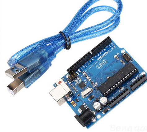
Currently DCC++ Base Stations can be built from either the Arduino Uno or Arduino Mega platforms. JMRI should support either platform via USB or Network connection.
Computer Interfaces
Simulator
To use the Simulator, simply choose that option in the JMRI Preferences. Note that some features do not work in the Simulator. For example, the Simulator does not (yet) support assigning, storing, and remembering Sensor and Turnout assignments. The Simulator interface is functional enough to keep JMRI «happy» while working on offline projects such as Operations or Panel and Logix design, but is not intended to be a full-fledged Base Station Emulator.
DCC++ Over TCP
For the DCC++ Over TCP, a host computer must be connected to the Base Station over a Serial or Network connection (or a simulator). This host computer then runs the DCC++ Over TCP Server. A remote computer (or several remote computers) can then use the DCC++ Over TCP (Server) interface to remotely access and control the Base Station.
Limitations
JMRI currently supports the V1.1 Base Station Interface. Some V1.0 commands may not work.
Connecting
Configuring an Arduino for use as a DCC++ Base Station
In order to use an Arduino as a Base Station, you must first assemble the device and download the Base Station firmware to it. Please follow the instructional videos linked below under Other Info.
Connecting to a DCC++ Base Station via USB
- To connect your computer to a DCC++ Base Station, first install the appropriate drivers.
-
- For the DCC++ Base Station with JMRI, you may need to install a device driver on your computer. Please refer to the Arduino Getting Started pages for instructions.
- Windows (See Step 4)
- Mac: No drivers should be required
- Linux
page
- For the DCC++ Base Station with JMRI, you may need to install a device driver on your computer. Please refer to the Arduino Getting Started pages for instructions.
Note: If you have already installed the Arduino IDE software, the device drivers should already be installed.
When the device drivers are installed, connect the Arduino Base Station to your computer using a standard USB cable.
Connecting to a DCC++ System using Network
- First, connect the DCC++ Base Station to wired or WiFi network and record the IP Address and Port number. You may need to connect the Arduino to a host computer temporarily and use the Arduino Serial Monitor to get this information.
- Now you are ready to configure JMRI. Start one of the JMRI-based programs, then go to the Preferences panel. This opens automatically the first time a JMRI program is run, or you can select it from the «Edit» menu (from the Application menu on OS X).
- Select «DCC++» from the top selection box («System Manufacturer»).
- Select «DCC++ Ethernet» from the second selection box («System Connection»).
- Input the IP Address and Port Number of the DCC++ Base Station.
- Click «Save». You’ll be asked if it’s OK for the program to quit, click «Yes».
- Restart the program. You should be up and running.
Connecting to a DCC++ System using DCC++ Over TCP
- First, connect the DCC++ Base Station to the host computer via the Serial or Network interface as described above.
- On the host computer select «Load DCC++ Over TCP Server» from the DCC++ Menu. Check the settings, then press the «Start Server» button. If you want the server to automatically start when JMRI is launched, click the checkbox provided.
- The Host computer must be running with the DCC++ Server active before launching the Client computer.
- On the client computer, launch JMRI on the Client computer.
- In the Connection Preferences, select DCC++ as the System Manufacturer.
- Select «DCC++ Server» as the System Connection Type.
- Enter the network name or IP address of the host computer and verify that the port number is the same as on the host computer.
- Save your Preferences and restart.
Once both the Host and Client instances of JMRI are configured, you can use the Client JMRI just the same as if it were directly connected to the Base Station. The client JMRI instance can be on the same computer, in the same house, or across the country from the host.
Connecting to the DCC++ Simulator
- Start one of the JMRI-based programs, Then go to the preferences panel. This opens automatically the first time a program is run, or you can select it from the «Edit» menu.
- Select «DCC++ Simulator» from the top selection box. There are no additional configuration steps required to use the DCC++ Simulator.
- Click «Save». You’ll be asked if it’s OK for the program to quit, click «Yes».
- Restart the program. You should be up and running.
JMRI DCC++ Tools
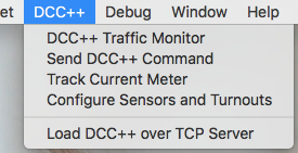
The DCC++ menu contains 5 tools:
- DCC++ Traffic Monitor
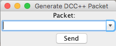
- Send DCC++ Command
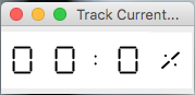
- Track Current Meter
- Configure Sensors and Turnouts
- Load DCC++ over TCP Server
Documentation
JMRI Help
Additional documentation will be provided on other pages linked here:
Third Party info
Thanks and congratulations to all who contributed! Contact us via the JMRI users Groups.io group.
Copyright © 1997 — 2022 JMRI Community. JMRI®, DecoderPro®, PanelPro™, DispatcherPro™, OperationsPro™, SignalPro™, SoundPro™, TrainPro™, Logix™, LogixNG™ and associated logos are our trademarks. Additional information on copyright, trademarks and licenses is linked here.
Dcc arduino uno
Arduino DCC Controller
Revised 09-23-14 & 3-12-15 & 9-20-15 & 2-29-16
| IMPORTANT Note (2-29-16)- You may want to look over the DCC++ system before building this unit — it is much more stable and is also much easier to build — see: |
| IMPORTANT Note (3-12-2015)- the IRRemote library will not work with newer versions of the Arduino program — I had to download version 1.0.1 from http://arduino.cc/en/Main/OldSoftwareReleases to get it to work. |
| Introduction I have been experimenting with using the Arduino to receive DCC commands in order to use small dedicated DCC decoders to operate animations and other non-locomotive things on my modular layout . |
Thanks to a posting by Geoff Bunza on the MRH forum. In that article Geoff describes how one can build a small decoder that can be used to trigger up to 17 discrete events. I have details about my experiments with this project here: http://www.trainelectronics.com/DCC_Arduino/
The next logical step is to create a dedicated DCC controller that can be used to trigger events. I found this listing http://railstars.com/software/cmdrarduino/ and have been testing the Arduino libraries and code with great success.
Please Note: The first design of a controller is shown on this web page: Arduino DCC Controller -first design
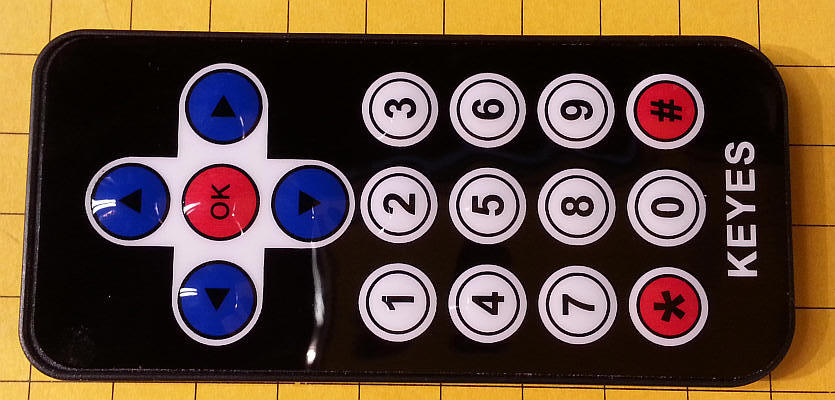
The design of the user interface must be considered before gathering parts and building any device. I have used infrared TV remote controls to operate any number of PIC and PICAXE based circuits and opted to do the same with this Arduino project. There are libraries available that make using them a trivial task. The software is set up to use just a few remote keys: the numbers 0-9, the four direction buttons (up, down, left, right), an OK button and the «*» & «#» keys. The basic remote is very compact:
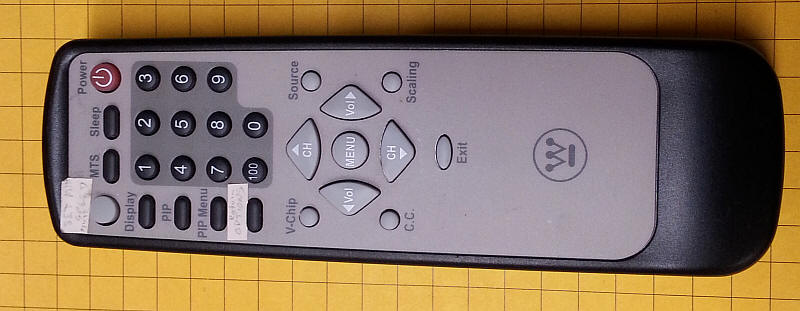
I also added codes for this Sony compatible remote. Those codes are the second code in each set as noted in the software.
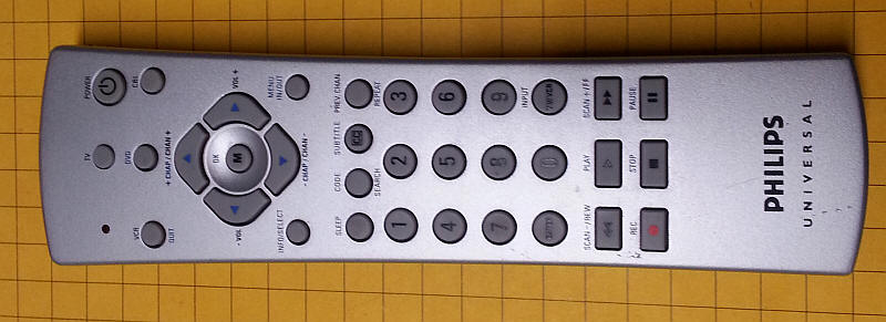
This universal remote is set for Sony codes and it works, too.
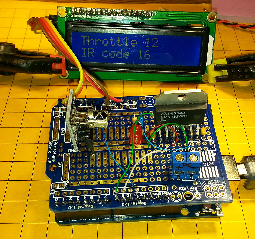
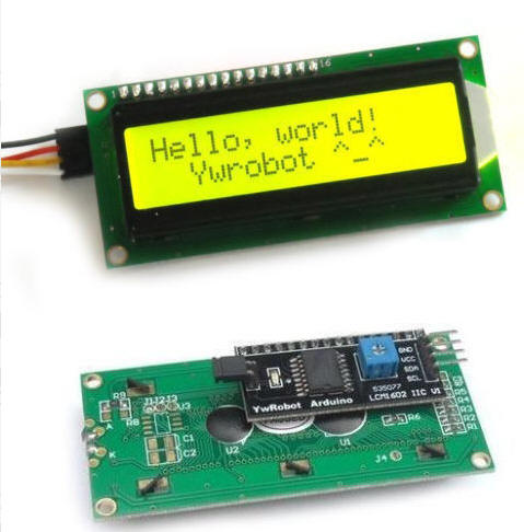
To give feedback on the controller’s settings and current state of operation a two line by 16 character LCD display was added. This is a device that only has four connections, +5 volts, ground and two for the I2C interface.
The up and down arrow keys accelerate or decelerate the locomotive. The «*» key stops the train and the number keys 1—9 activate auxiliary functions. The zero key («0») resets all functions to «off».
The locomotive’s DCC address is set by pressing the OK button. A two digit (00-99) address can be entered. Press OK again to return to the main screen. Note that the address is retained in memory until it is reset.
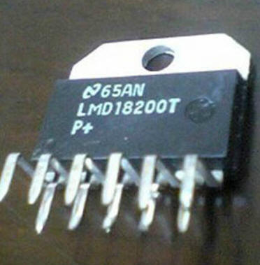
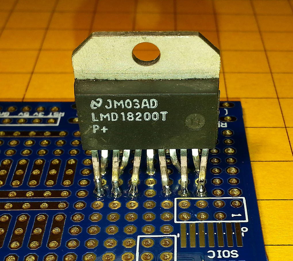
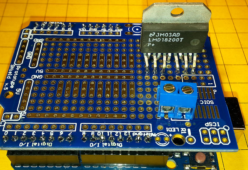
Since this is designed to be a stand-alone DCC controller power needs to be added to the DCC signals created by the Arduino. This functionality is provided by the 11 pin LMD18200 H-Bridge. This device is frequently used to power DC motors as it contains the electronic equivalent of a double pole, double throw toggle switch. This, along with the ability to change speed of a motor with a PWM signal, allows speed and direction control.
In this application the direction pin (pin 5) accepts the DCC signal and applies it to the track power. Note that the PWM pin (pin 5) is pulled high and that the brake pin (pin 4) is pulled low by the Arduino’s pin 8. This allows you to disable power to the track by changing pin 8 from low to high.
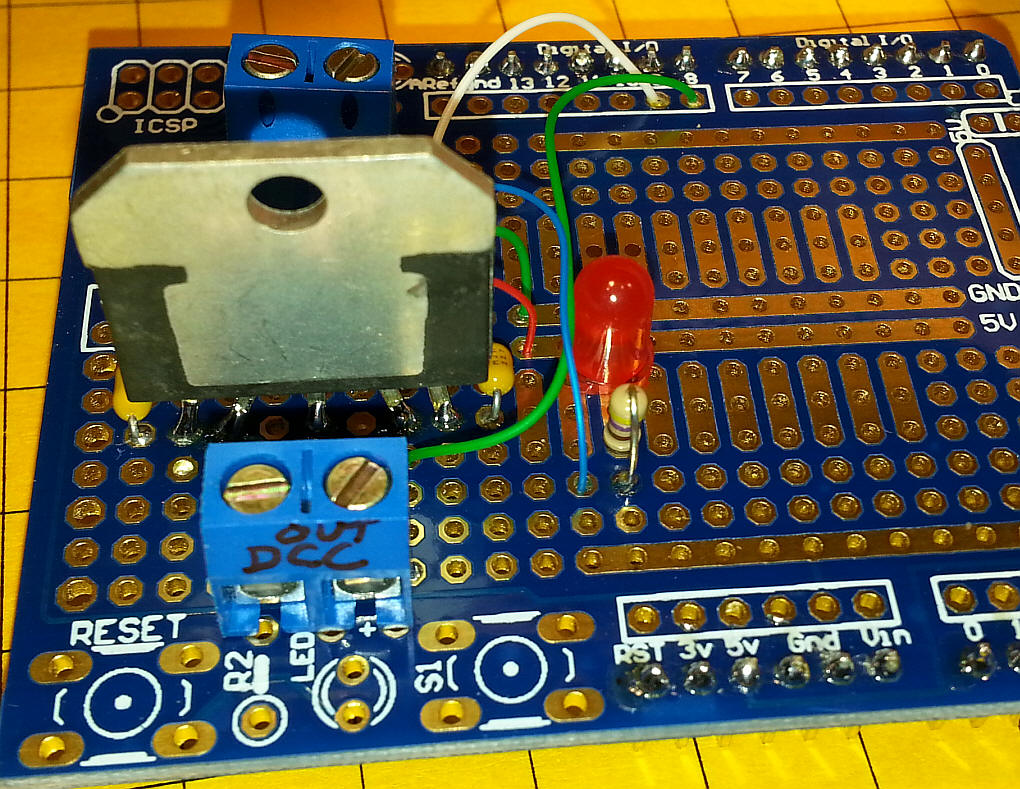
In keeping with the «shield» theory of building circuits for the Arduino I decided to build up a single board DCC controller circuit. The parts that were used are shown here.
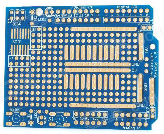

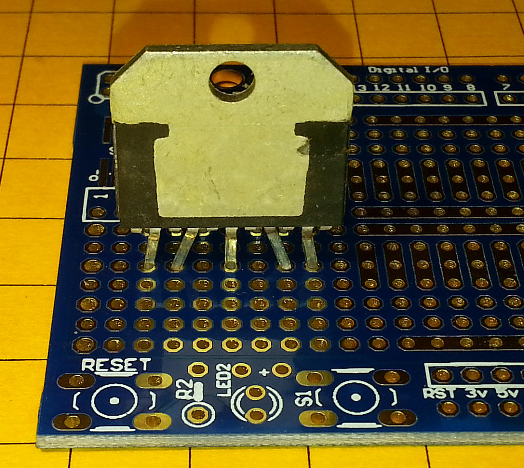
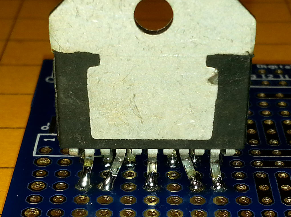
There is a row of unused holes between the front pins and the back pins.
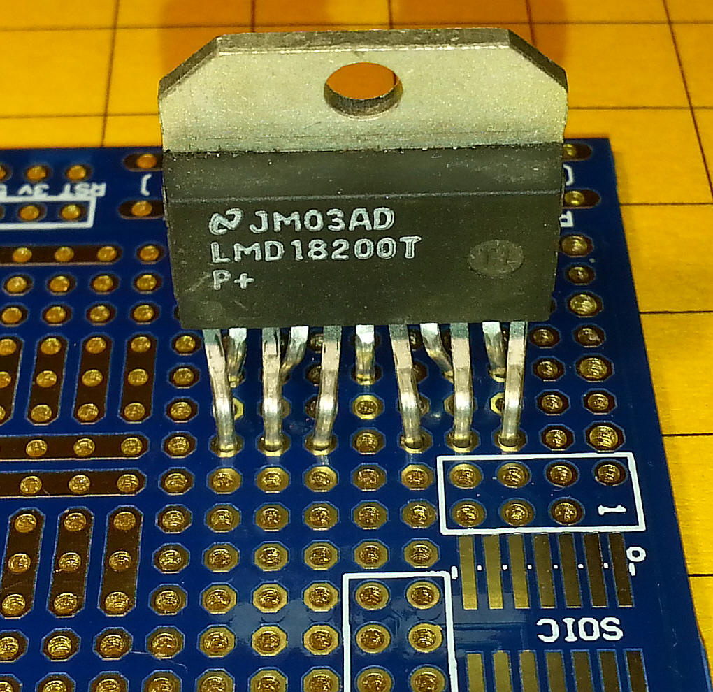
When you solder the pins make sure that solder is on both sides of the board.
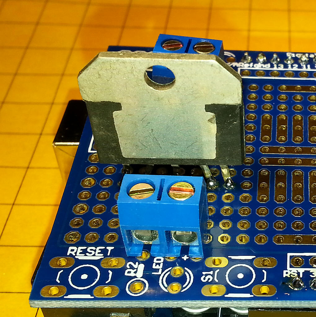
Two terminal blocks supply 12 volts DC (the block at the back of the photo) and connect DCC to the track (the block in the foreground).
Some of the wiring is on the top of the board.
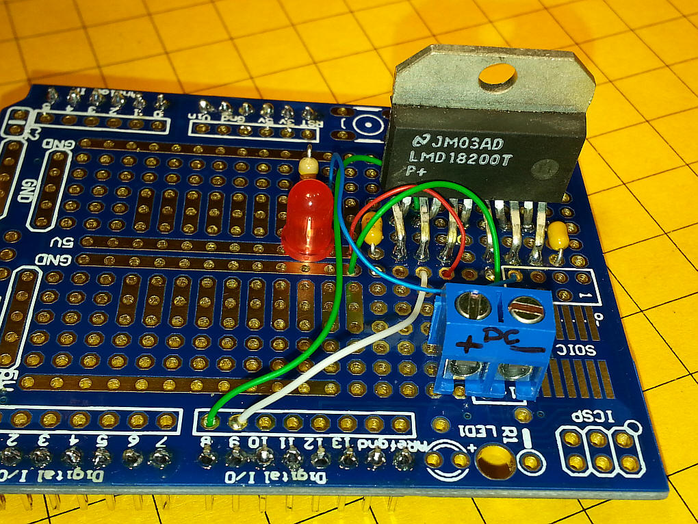
And some of the wiring is on the back. Heavier wire was used for the DC in and DCC out connections.
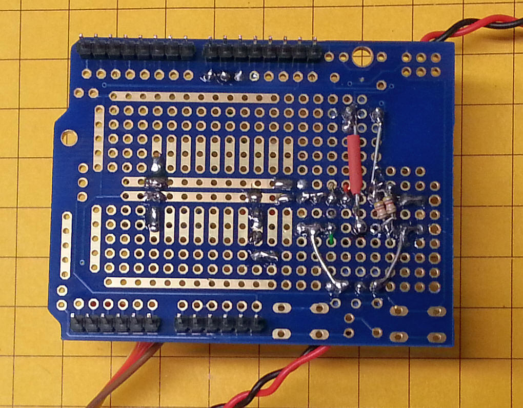
The red LED connects to the Thermal Warning pin on the LM18200.
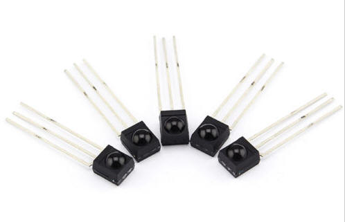
The little block to the left, labeled Keyes, contains the IR detector that «sees» the IR from the TV remote. The one shown came with the Keyes remote kit.
The power that goes to the DC terminals is separate from the USB power that goes to the Arduino. If you want to run the unit from one supply disconnect the USB and feed the power that goes to the DC in terminals to the power plug on the Arduino.

The LCD has four connections on its back. GND goes to ground, VCC to 5 volts, SDA to pin A1 and SCL to pin A0.
Adblockdetector