Arduino Capacitive Sensor In less Than 2 Minutes © GPL3+
Hello! Today I will show you how to make a capacitive sensor with Arduino UNO.
Today I will show you how to make a capacitive sensor with Arduino UNO.
Step 1: Watch the video .
Step 2: Parts for the project
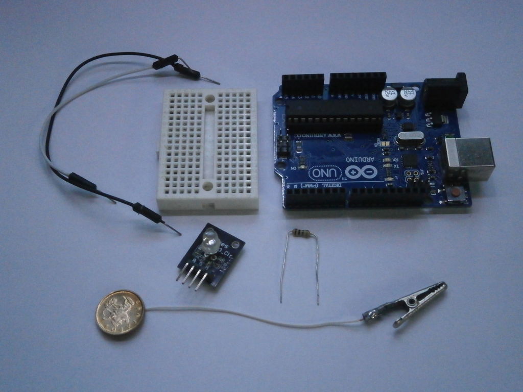
- 1 x Arduino board
- 1 x 1M resistor
- 1 x Touch plate
- 1x Breadboard
- 1 x LED
- 2 x Jumpers
Step 3: Put all together
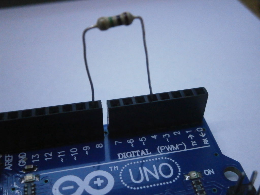
First plug in the resistor in pin 4 and pin 8 of the Arduino, then connect the touch plate with pin 8 of the Arduino.
Now plug in the LED to the breadboard, connect LED’s «-» to Arduino’s GND and «+» to pin 7.
Step 4: Upload the sketch
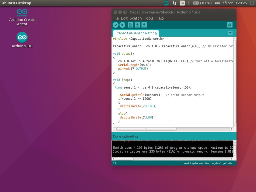
Connect your Arduino to a computer and upload the sketch which you can get from here .
You will also need this library .
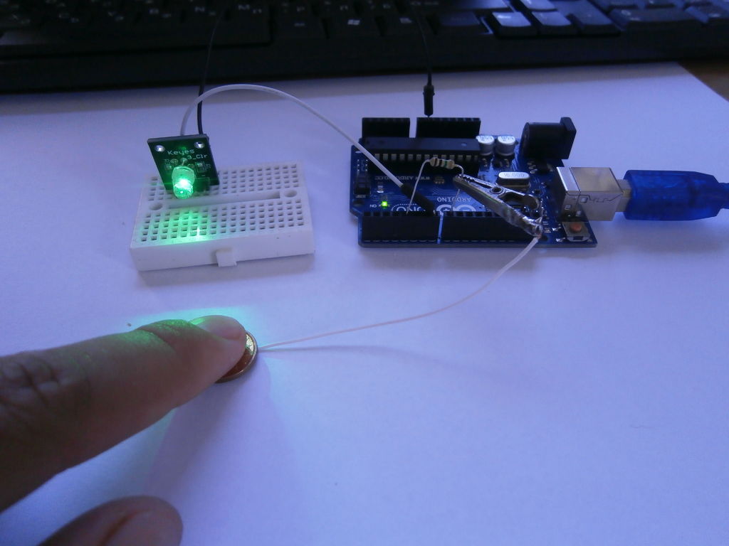
You are done, touch the plate and the LED should light up. You can modify the sketch and for other «capacitive» needs.
OUR PRIVACY POLICY HAS BEEN UPDATED
The playground is a publicly-editable wiki about Arduino.
Capacitive Sensing Library
Download
This updated CapacitiveSensor version 05 adds support for Arduino Due and other non-AVR boards.
Overview
The capacitiveSensor library turns two or more Arduino pins into a capacitive sensor, which can sense the electrical capacitance of the human body. All the sensor setup requires is a medium to high value resistor and a piece of wire and a small (to large) piece of aluminum foil on the end. At its most sensitive, the sensor will start to sense a hand or body inches away from the sensor.
Version 04 adds support for Arduino 1.0, and fixes an obscure possible race condition with Tone, Servo and other libraries that perform I/O in interrupt context.
Version 03 has been updated to C++ and supports multiple inputs. It also includes some utility functions to make it convenient to change timeout values.
Applications
Capacitive sensing may be used in any place where low to no force human touch sensing is desirable. An Arduino and the library may be used to sense human touch through more than a quarter of an inch of plastic, wood, ceramic or other insulating material (not any kind of metal though), enabling the sensor to be completely visually concealed.
A capacitive sensor covered with paper or other insulator also acts as fairly good (human touch) pressure sensor with an approximately logarithmic response. In this regard it may surpass force sensing resistors in some applications.
How it works
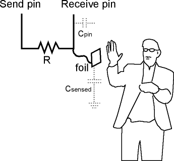
The capacitiveSensor method toggles a microcontroller send pin to a new state and then waits for the receive pin to change to the same state as the send pin. A variable is incremented inside a while loop to time the receive pin’s state change. The method then reports the variable’s value, which is in arbitrary units.
The physical setup includes a medium to high value (100 kilohm — 50 megohm) resistor between the send pin and the receive (sensor) pin. The receive pin is the sensor terminal. A wire connected to this pin with a piece of foil at the end makes a good sensor. For many applications, a more useful range of values is obtained if the sensor is covered with paper, plastic, or another insulating material, so that users do not actually touch the metal foil. Research has shown that a small capacitor (100 pF) or so from sensor pin to ground improves stability and repeatability.
When the send pin changes state, it will eventually change the state of the receive pin. The delay between the send pin changing and the receive pin changing is determined by an RC time constant, defined by R * C, where R is the value of the resistor and C is the capacitance at the receive pin, plus any other capacitance (e.g. human body interaction) present at the sensor (receive) pin. Adding small capacitor (20 — 400 pF) in parallel with the body capacitance, is highly desirable too, as it stabilizes the sensed readings.
Library Methods
The library contains three main methods and some utility methods:
CapacitiveSensor CapacitiveSensor (byte sendPin, byte receivePin)
CapacitiveSensor creates an instance of the library (please note the capital letters, this is not the same method as below)
long capacitiveSensorRaw(byte samples)
capacitiveSensorRaw requires one parameter, samples, and returns a long integer containing the absolute capacitance, in arbitrary units. The samples parameter can be used to increase the returned resolution, at the expense of slower performance. The returned value is not averaged over the number of samples, and the total value is reported.
capacitiveSensorRaw will return -2 if the capacitance value exceeds the value of CS_Timeout_Millis (in milliseconds). The default value for CS_Timeout_Millis 2000 milliseconds (2 seconds).
long capacitiveSensor(byte samples)
capacitiveSensor requires one parameter, samples, and returns a long containing the added (sensed) capacitance, in arbitrary units. capacitiveSensor keeps track of the lowest baseline (unsensed) capacitance, and subtracts that from the sensed capacitance, so it should report a low value in the unsensed condition.
The baseline is value is re-calibrated at intervals determined by CS_Autocal_Millis. The default value is 200000 milliseconds (20 seconds). This re-calibration may be turned off by setting CS_Autocal_Millis to a high value with the set_CS_AutocaL_Millis() method.
void set_CS_Timeout_Millis(unsigned long timeout_millis);
The set_CS_Timeout_Millis method may be used to set the CS_Timeout_Millis value, which determines how long the method will take to timeout, if the receive (sense) pin fails to toggle in the same direction as the send pin. A timeout is necessary because a while loop will lock-up a sketch unless a timeout is provided. CS_Timeout_Millis’ default value is 2000 milliseconds (2 seconds).
void reset_CS_AutoCal()
reset_CS_AutoCal may be used to force an immediate calibration of capacitiveSensor function.
void set_CS_AutocaL_Millis(unsigned long autoCal_millis)
The method set_CS_AutocaL_Millis(unsigned long autoCal_millis) may be used to set the timeout interval of the capacitiveSensor function. Re-calibration may be turned off by using set_CS_AutocaL_Millis to set CS_AutocaL_Millis to «0xFFFFFFFF».
Resistor Choice
Here are some guidelines for resistors but be sure to experiment for a desired response.
- Use a 1 megohm resistor (or less maybe) for absolute touch to activate.
- With a 10 megohm resistor the sensor will start to respond 4-6 inches away.
- With a 40 megohm resistor the sensor will start to respond 12-24 inches away (dependent on the foil size). Common resistor sizes usually end at 10 megohm so you may have to solder four 10 megohm resistors end to end.
One tradeoff with larger resistors is that the sensor’s increased sensitivity means that it is slower. Also if the sensor is exposed metal, it is possible that the send pin will never be able to force a change in the receive (sensor) pin, and the sensor will timeout.
Note that the hardware can be set up with one sPin and several resistors and rPin’s for calls to various capacitive sensors. See the example sketch.
Grounding and other known issues
The grounding of the Arduino board is very important in capacitive sensing. The board needs to have some connection to ground, even if this is not a low-impedance path such as a wire attached to a water pipe.
Capacitive sensing has some quirks with laptops unconnected to mains power. The laptop itself tends to become sensitive and bringing a hand near the laptop will change the returned values.
Connecting the charging cord to the laptop will usually be enough to get things working correctly. Connecting the Arduino ground to an earth ground (for example, a water pipe) could be another solution.
Another solution that seems to have worked well on at least one installation, is to run a foil ground plane under the sensor foil (insulated by plastic, paper, etc.), and connected by a wire to ground. This worked really well to stabilize sensor values and also seemed to dramatically increase sensor sensitivity.
Scroll Wheels (well, slide pots anyway)
Experiments with a slide pot type linear sensor have been successful with just two pins and a resistance ladder. The basic layout is shown in the Quantum Scrollwheel sensor datasheet.
The code uses this type of arrangement
Where the pins switch their send and receive positions. With a linear resistance ladder, a finger closer to the send pin will report lower values because resistance downstream from the capacitance is basically out of the circuit.
So in this manner when a finger is moved from one pin to the other the two calls to capacitiveSensorRaw will report complementary values that have an approximately constant value to them. The complication comes in when trying to deal with how much contact (capacitance) is present, which raises (or lowers) both values, but not necessarily in a linear manner.
At some point I’ll get the sketch posted here.
Error Messages
capacitiveSensor and capacitiveSensorRaw will return -1 with an invalid choice of pin parameter, but it appears that this feature is not working at this writing. Engineers are working on this, stand by.
capacitiveSensor and capacitiveSensorRaw will return -2 if the methods timeout. This is caused by the count exceeding the value of CS_Timeout_Millis, which is set at a default value of 2000 milliseconds (2 seconds). This is most often caused by a missing resistor or the resistor in the wrong pin. It could also be caused by a sensor that is grounded or connected to +5 V.
A timeout is necessary because the while loop that does the timing in the CapacitiveSensor method, will lock-up the sketch (the function will never return) if, for example, the resistor between sendPin and receivePin becomes disconnected.
Installation
- Download CapacitiveSensor04.zip
- Unzip, and add to Arduino/hardware/libraries/
- To add capacitiveSensor to a new sketch choose Sketch->Import Library-> CapacitiveSensor
Demo Sketch
Example code: Threshold
Instead of using capacitors, you may use a function to count relevant values, and reset the count when encountering lower values (interferences). This is a code example for a touch lamp. It require to either touch the pin 8 wire or to get close to an antenna, and it stops the readings when the threshold is reached. You might want to adjust values A, B and C according to your particular project.
Bugs, suggestions, applications
Please post bugs, suggestions, amazing feats on this forum thread
Capacitive Fingerprint Sensor with an Arduino or ESP8266 © GPL3+
Protect your projects by making them fingerprint-secured with sleek, compact and fast ID809 Capacitive Fingerprint Sensor.
Hey, what’s up, Guys! Akarsh here from CETech.
Today we are going to add a protective layer to our projects. Don’t worry we are not going to appoint any bodyguards for the same. It will be a cute little good looking fingerprint sensor from DFRobot.
So as I mentioned above, today we are going to interface a Capacitive Fingerprint Sensor from DFRobot with Arduino UNO and after that, we will test three functions of this sensor which are adding a fingerprint, Checking the added fingerprint, and after that deleting the added fingerprint.
So let’s get to the fun part now.
Get PCBs for Your Projects Manufactured
PCBGOGO, established in 2015, offers turnkey PCB assembly services, including PCB manufacturing, PCB assembly, components sourcing, functional testing, and IC programming.
Its manufacturing bases are equipped with the most advanced production equipment such as YAMAHA pick and place machine, Reflow oven, Wave soldering Machine, X-RAY, AOI testing machine; and the most professional technical personnel.
Though it’s only five years old, their factories have experience in the PCB industry for over 10 years in Chinese markets. It is a leading specialist in surface-mount, thru-hole, and mixed technology PCB assembly and electronic manufacturing services as well as turnkey PCB assembly.
PCBGOGO provides the order service from prototype to mass production, join them now.
About the Capacitive Fingerprint Sensor
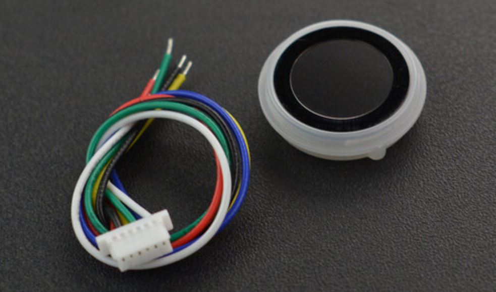
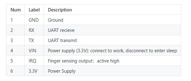
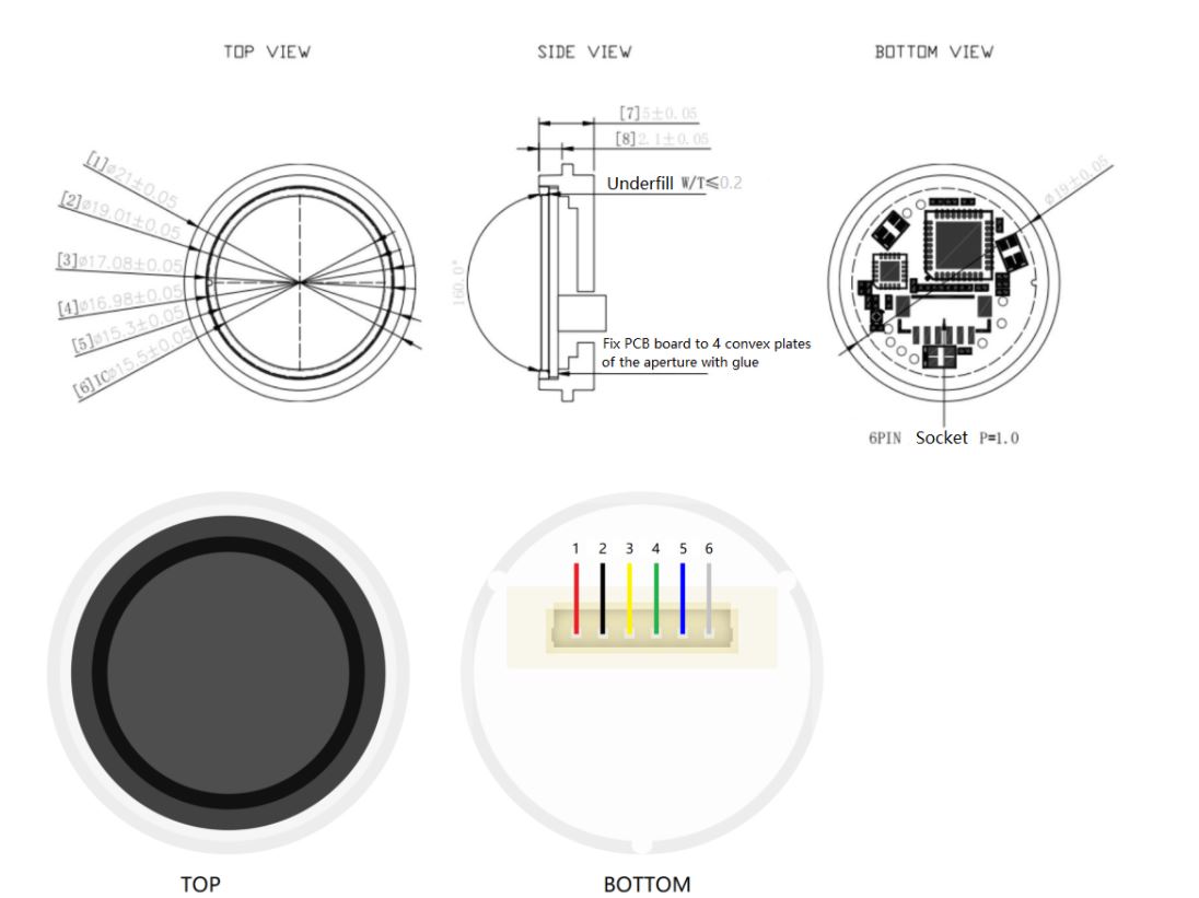
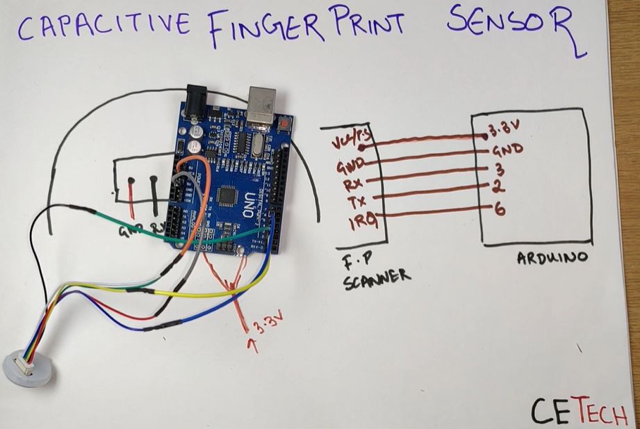
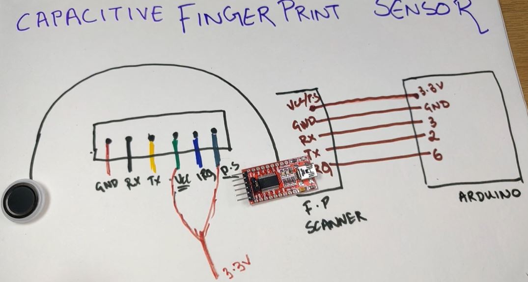
The Capacitive Fingerprint Sensor is a nice and compact one that is similar to the one at the back of your smartphone. It comes with round breathing LEDs and has a simple structure, small size, and delicate appearance. The sensor offers fast recognition speed and high security. It supports 360-degree arbitrary angle recognition and deep self-learning function, high performance, and low power consumption. Loaded with ID809 high-performance processor and semiconductor fingerprint sensor as the core, the sensor adopts a built-in IDfinger6.0 algorithm, which can complete all fingerprint identification work independently. This sensor supports UART communication and while working with the Arduino library, it can easily realize functions like fingerprint registration, fingerprint deletion, etc. It is a 6 pin device that can be easily connected to microcontrollers by virtue of the pitch connecter that comes with it. But one thing to keep in mind is that the color-coding of the wires that comes with this device is different from the normal coding. So we need to take care of it while doing the connections. The color coding is as given below:-
- Red Wire = Ground Pin
- Black Wire= Rx(Receiver Pin)
- Yellow Wire= Tx(Transmitter Pin)
- Green Wire= Vcc Pin
- Blue Wire= IRQ Pin(Interrupt Request Pin that is capable of receiving external Interrupts)
- White/Grey Wire= Power Supply Pin
So here we are using two pins which see to be similar but have different functions these are the Vcc and Power supply pin. The function of the Vcc pin is that it acts as an enabling pin. When there is a power input at this pin then only the sensor will work otherwise not. On the Other hand, the Power Supply Pin is there to Power Up the device or turn it ON.
Technical Specifications and Applications of the Sensor
The Technical Specifications of this Sensor are as given below:-
- Operating Voltage: 3.3V
- Operating Current: Connecting the Sensor With Arduino
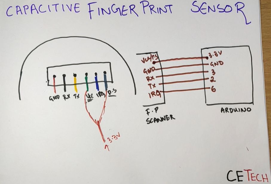
For performing the operations such as Fingerprint recording, Recognizing, and Deleting we first need to connect the Sensor to Arduino UNO by following the steps given below:-
- Connect the Vcc and Power Supply Pin(Green and White Wire respectively) of the Fingerprint Scanner to the 3.3V pin of the Arduino UNO.
- Connect the Ground Pin(Red Wire) of the Scanner to the GND pin of the Arduino.
- Connect the Rx Pin(Black Wire) of the Scanner to the Digital Pin 3 of the Arduino.
- Connect the Tx Pin(Yellow Wire) of the Scanner to the Digital Pin 2 of the Arduino.
- And at last, Connect the IRQ Pin(Blue Wire) of the Scanner to the Digital Pin 6 of the Arduino.
In this way, The Fingerprint Scanner is connected to the Arduino UNO and is ready to be coded. So now we need to connect the Arduino to our PC for the next step.
Coding the Arduino Board
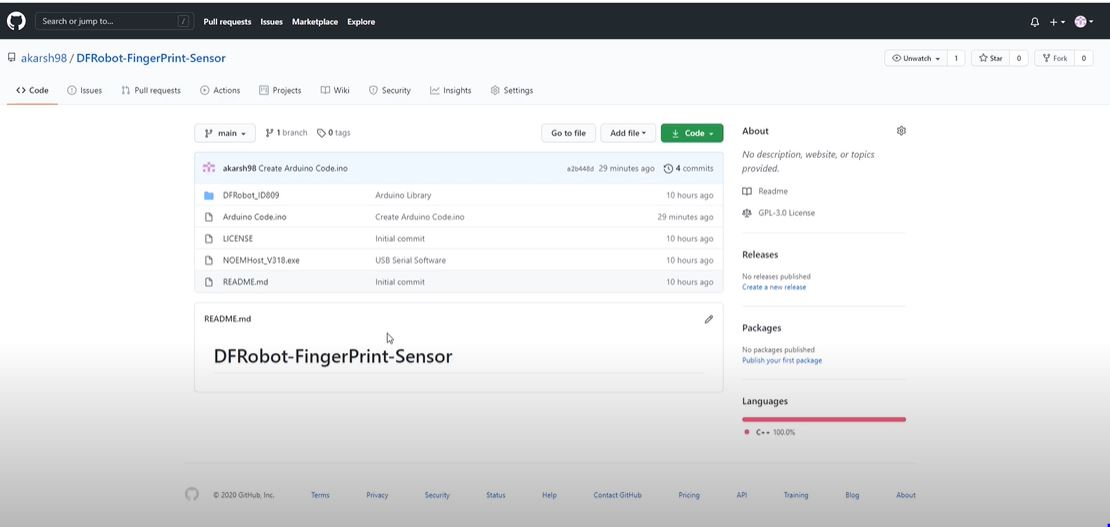
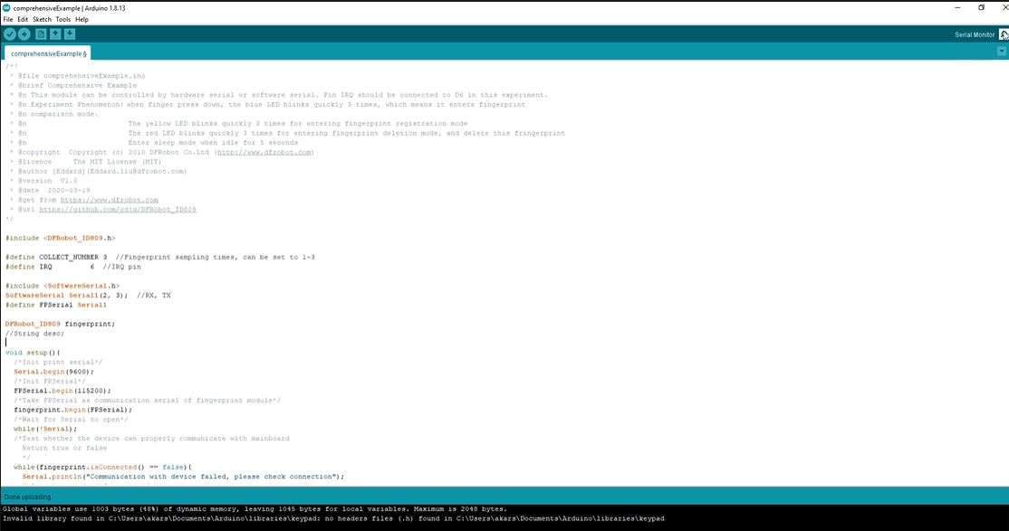
Now in this step, we are going to upload the code to our Arduino UNO board. As soon as the code gets uploaded, The Scanner will be capable of storing a new fingerprint, recognizing the fingerprint, and also deleting the same. For this step, you need to refer to the Github repository of this project from here and after that follow the steps given below:-
- First of all, you need to download the DFRobot_ID809 file from the Github repository. It is the Arduino library for the Fingerprint Scanner. After downloading this, you need to put it in the Arduino libraries folder.
- After that, you need to open the file named Arduino Code.ino. This is the code that needs to be uploaded to the Arduino. Paste this code in your Arduino IDE. Select the correct board, COM Port, and hit the upload button.
And with these steps, Our Fingerprint Scanner is ready to use and we will test the functions of it in the next step.
Playing With the Scanner
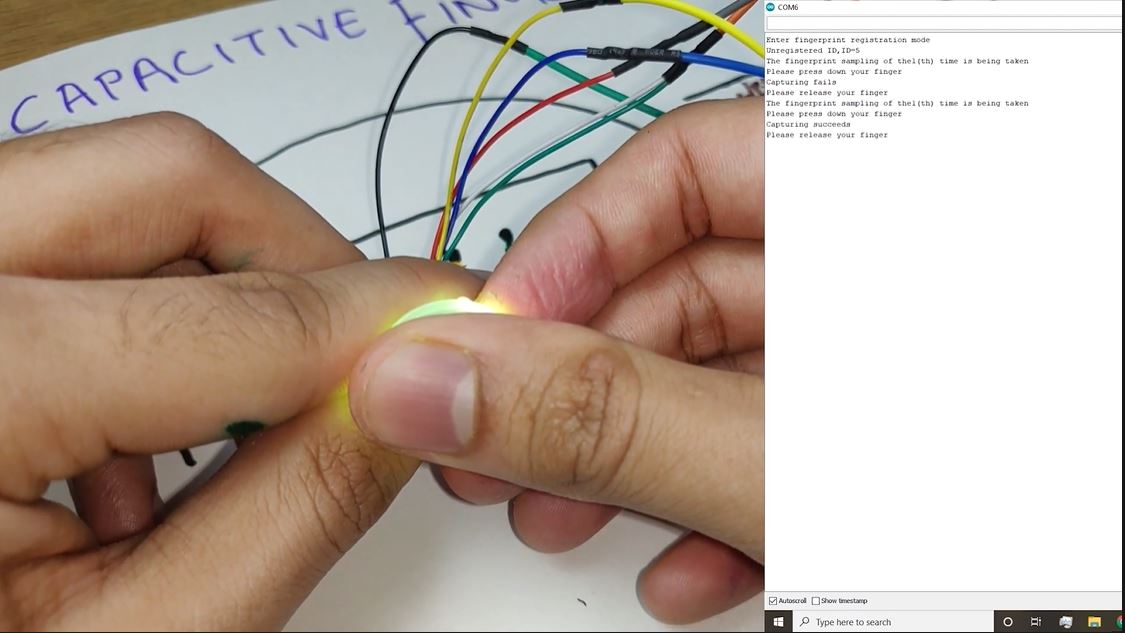
The code that we just uploaded had three functions in it. Those functions are Reading and Testing the Fingerprint, Adding a new fingerprint, and Deleting any added Fingerprint. So now we will be testing these functions. For that, we first need to open the Serial Monitor which will display messages according to the task performed. We will hover around each of the operations one by one.
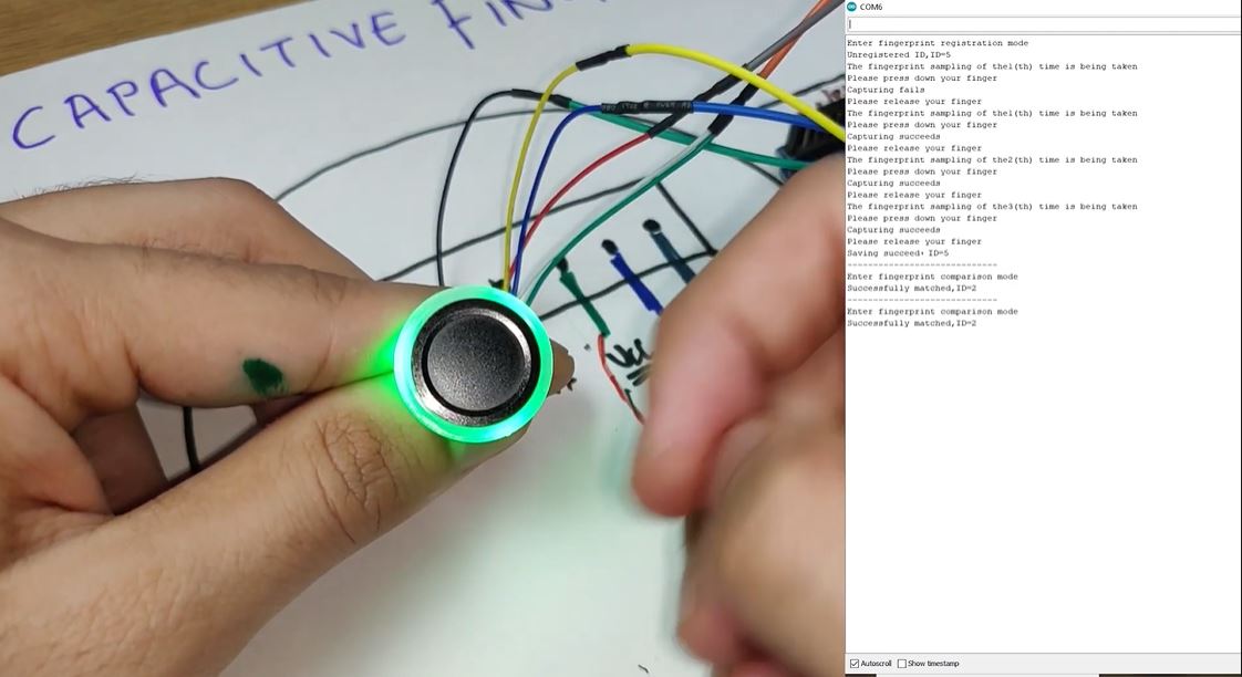
- Adding a new fingerprint : For this operation, we need to place our finger on the Scanner you will see a blue light blink. Keep finger placed there until the yellow light blinks three times and then release the finger. This shows that the scanner has entered the fingerprint adding mode and as our fingerprint is not already added to the scanner that’s why it would show unregistered on the Serial Monitor and assign an ID to the same. After that, we need to put our finger on the scanner again and wait till the yellow light blinks and then we can release the scanner. We need to repeat this process of placing the finger on the scanner and releasing two more times and in total three times to add our fingerprint. As we complete the scanning for the third time we will see a green light in place of the yellow light. This shows that the fingerprint is added successfully and the same can be seen on the serial monitor as well.
- Testing a Fingerprint : Now we can test the added fingerprint by placing the thumb on the scanner again. This time we have to remove our finger after the blinking of the blue light and we will see that the green light turns on and a message on the Serial monitor will appear saying successfully matched with the ID of the fingerprint.
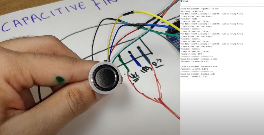
- Deleting the Fingerprint : For deleting the fingerprint we need to place our finger on the scanner and keep it placed there until the red light blinks. First of all, a blue light will blink which is the option for testing the fingerprint. After that, a yellow light will blink which is the option for adding a new fingerprint and in the end, the red light will blink which shows that the fingerprint is deleted and a message on the Serial monitor will show that the Fingerprint with ID No. is deleted. After deletion, If we place our finger on the scanner for testing, The red light will blink and the serial monitor would show a message saying that the Fingerprint not matched.
In this way, we will be able to interface the fingerprint scanner to the Arduino IDE and can add it to our projects wherever possible.
Another Way to Connect the Scanner
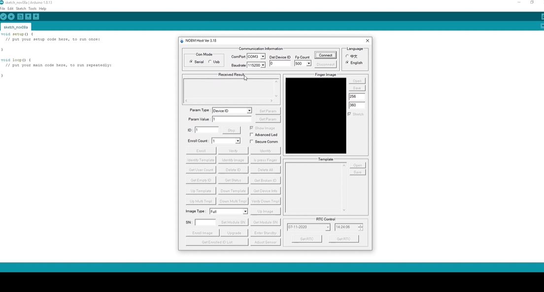
It is an alternative way of connecting the Fingerprint Scanner. What we can do is that we can connect the scanner to a USB to Serial Converter before connecting it directly to the Arduino. For that, we need to connect the Vcc and GND pins of the Scanner to the Vcc and GND pins of the Converter. After that, we need to connect the Rx pin of the Scanner to the Tx pin of the Converter and the Tx pin of the Scanner to the Rx pin of the converter and in this way, the scanner is connected to the converter. Now we can connect the converter to our laptop and after that, we need to open the NOEM Host Software. The Software is available on the Github repository of this project. You can refer to that from here. Download it and then open it.
There you need to select the COM Port and Baud rate and you are ready to use the software. There are a lot of operations that can be performed using that software such as viewing the image of the fingerprint captured, Perform a check of the fingerprint, and many more.
So in this way, we have learned how to interface a Capacitive fingerprint Sensor to the Arduino and use it in our projects. Hope you liked the Tutorial. Looking forward to seeing you next time. Until then enjoy Electronics.

