Ардуино: оптический датчик препятствия
Каждый робот, способный ездить, летать или плавать, должен видеть препятствия, находящиеся у него на пути. Чтобы робот смог это сделать, ему необходимы соответствующие датчики. В английской литературе такие устройства называют proximity sensor, мы же их будем называть датчиками препятствия.
На этом уроке мы рассмотрим один из самых распространенных датчиков препятствия, который работает по принципу отражения. Устроен он очень просто. Датчик содержит направленный источник света и детектор света. Источником часто служит инфракрасный светодиод с линзой, а детектором — фотодиод или фототранзистор.

Светодиод на датчике постоянно включен и излучает узкий пучок света в прямом направлении. Если перед датчиком есть препятствие (рисунок А), то на детектор попадает отраженный свет от источника, и на выходе датчика появляется положительный импульс. В противном случае, если препятствия нет, то датчик молчит (рисунок Б). Есть и третий вариант, когда препятствие есть, но свет от него не отражается! На рисунке В изображен как раз такой случай. Получается, матовую черную поверхность робот не увидит.
1. Подключение
Будем подключать самый простой датчик с цифровым выходом. Принципиальная схема подключения к выводам Ардуино Уно:

Внешний вид макета

2. Настройка чувствительности
Как известно, вокруг нас имеется множество источников инфракрасного излучения, включая лампы освещения и солнце. Фоточувствительный элемент датчика регистрирует это фоновое излучение, и может дать ложный сигнал срабатывания. Другими словами, датчик препятствия может сработать, когда никакого препятствия и нет вовсе.
Чтобы решить эту проблему, на датчике имеется возможность настроить чувствительность таким образом, чтобы воспринимать только свет достаточной силы. Обычно это реализуется с помощью компаратора — электронного устройства, позволяющего сравнивать два уровня напряжения. Одно напряжение подается на компаратор с фотодиода, а другое с делителя напряжения на основе потенциометра. Второе напряжение будем называть пороговым. Теперь датчик даст положительный сигнал только тогда, когда напряжение на фотодиоде станет больше, чем настроенное нами.
Для настройки порогового напряжения нам понадобится шлицевая отвертка (она же — плоская). В этой процедуре нам также поможет зеленый светодиод состояния, который загорается когда датчик регистрирует достаточный уровень инфракрасного света. Алгоритм настройки сводится к трем шагам:
- помещаем датчик в условия освещенности, в которых он будет работать;
- подключаем датчик к питанию, при этом на нем загорится красный светодиод;
- убираем перед датчиком все препятствия, и крутим потенциометр до тех пор, пока зеленый светодиод состояния не погаснет.
Для проверки поднесем к датчику ладонь, и на определенном расстоянии загорится зеленый светодиод. Уберем руку — светодиод погаснет. Расстояние на котором датчик регистрирует препятствие зависит от уровня фоновой засветки, от настройки чувствительности и от правильного расположения фотодиода и светодиода на датчике. Они должны быть расположены строго параллельно друг другу.
Теперь, когда датчик настроен должным образом, приступим к составлению программы.
3. Программа
Для примера, будем зажигать и гасить штатный светодиод №13 на Ардуино Уно, в зависимости от показаний датчика.
При использовании цифрового датчика, программа будет такой же, как и в случае работы с кнопками. На каждой итерации цикла loop мы считываем значение на выводе №2, и затем сравниваем это значение с уровнем HIGH. Если значение равно HIGH, значит датчик видит препятствие, и мы зажигаем светодиод на выводе №13. В противном случае — гасим светодиод.
4. Пример использования
Попробуем теперь применить цифровой датчик по прямому назначению. Заставим двухколесного робота реагировать на показания двух датчиков, размещенных слева и справа.

Сделаем так, чтобы при обнаружении препятствия робот отворачивал от него в противоположную сторону, а затем продолжал движение вперед. Оформим программу в виде блок-схемы процедуры loop.

Задания
Если все получилось, попробуйте выполнить еще несколько заданий с роботом.
- Направить датчики препятствия вниз, чтобы робот смог чувствовать край стола. Написать программу, которая предотвращает падение робота со стола.
- Снова направить датчики вниз, но на этот раз для другой цели. Как мы выяснили, датчик может отличить черную поверхность от белой. Воспользуйтесь этим свойством, чтобы сделать робота-следопыта (он же LineFollower).
- Направить датчики в стороны, и заставить робота двигаться вдоль стены.
К размышлению
На следующем уроке мы познакомимся с датчиком, который устроен практически так же, но больше подходит для детектирования черных и белых поверхностей. Попробуем считывать уже не цифровой, а аналоговый сигнал, чтобы сделать более совершенного робота-следопыта.
Как подключить датчик препятствия к Ардуино

Оптический датчик препятствия (KY-032) — это один из самых распространенных датчиков, который прекрасно подойдет роботу или машинке на Ардуино для объезда препятствий. Датчик очень прост по принципу своей работы и способу подключения к плате Arduino Uno. Рассмотрим устройство датчика, схему его подключения и рассмотрим несколько примеров программ для работы с avoid sensor arduino.
Характеристики датчика препятствия (KY-032)
Схема работы ИК датчика препятствий довольно простая. На модуле расположен инфракрасный светодиод с линзой, который постоянно включен и излучает узкий пучок ИК излучения. Детектором отраженного сигнала от препятствия служит фотодиод или фототранзистор. Также на печатной плате расположен светодиод для индикации и два подстроечных резистора для настройки чувствительности датчика ky-032.
Устройство излучает инфракрасный луч с частотой 38 кГц, который принимается приемником на плате. При приближении предмета к сенсору (необходимое расстояние регулируется потенциометром на модуле) на выходе платы «OUT» появляется низкий уровень напряжения и включается встроенный светодиод. Дальность срабатывания (чувствительность) датчика препятствия регулируется от 2 до 40 сантиметров.
Подключение датчика препятствия к Arduino
Для этого занятия потребуется:
- Arduino Uno / Arduino Nano / Arduino Mega;
- датчик препятствия KY-032;
- беспаечная макетная плата;
- светодиод и резистор;
- провода «папа-мама», «папа-папа».
Для подключения датчика обнаружения препятствий к Arduino имеется три или четыре контакта. Два контакта на модуле KY-032 служат для питания от 5V (схему подключения датчика смотри на картинке выше). Еще два контакта формируют импульсы для платы Arduino Mega или Arduino Uno. Для примера работы рассмотрим скетч, который будет включать светодиод при появлении препятствия.
Счетч для датчика препятствий (KY-032)
Пояснения к коду:
- для приема сигнала с датчика KY-032 используется порт A1, который можно поменять в программе на любой порт общего назначения;
- датчик отправляет сигнал «логическая единица» при появлении препятствия.
Заключение. Для создания шагающего робота или автономной машинки на Ардуино сенсор KY-032 отлично подойдет начинающему программисту. Датчик препятствия более прост в настройке и подключении, в отличии от дальномера HC-SR04. При этом сенсор хорошо справляется с распознаванием объектов перед ним и может использоваться в машинках для объезда препятствий или езде по лабиринту.
Infrared Obstacle Avoidance Sensor with Visuino © GPL3+
Connect Infrared Obstacle Avoidance Sensor to Arduino Nano and program it to detect obstacles — Quick and Easy!
Infrared Obstacle Avoidance sensors are cheap, small sensors often used in robots, and Arduino project to detect objects near the sensor.
The Infrared sensors work by sending an infrared light with some frequency, and then detecting if some of the light has reflected back to the sensor. The most common ones have a digital output indicating if object has been detected. Many of them have the option to be enabled or disabled.
In this tutorial, I will show you how easy it is to connect and use such sensor with Arduino.
Some of the sensors have a brief false detection when they are enabled. In the tutorial, I will also show you how you can suppress this false detection with Visuino .
Step 1: Components
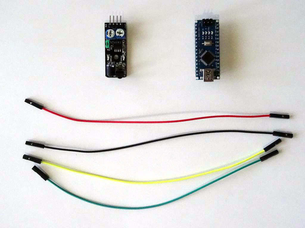
- One Arduino compatible board (I use Arduino Nano , because I have one, but any other will be just fine)
- One Infrared Obstacle Avoidance Sensor module I got from this cheap 37 sensors set
- 4 Female-Female jumper wires
Step 2: Understand the Infrared Obstacle Avoidance Sensor
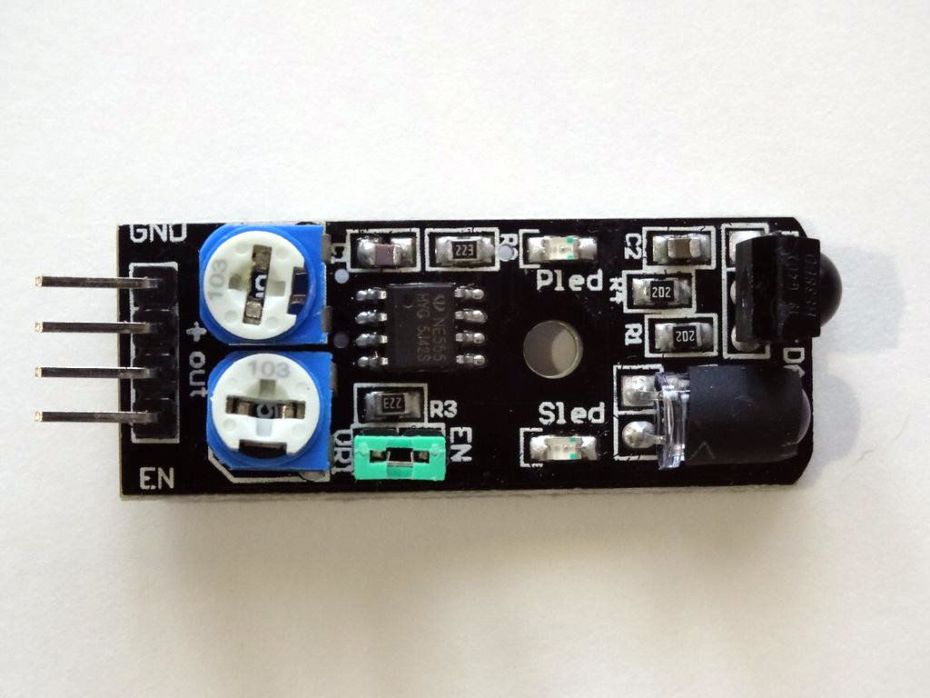
The Obstacle Avoidance Sensors usually come in two types — with 3 and 4 pins. The 3 pin version does not have the ability to be enabled/disabled. The 4 pin version has optional Enable pin. Here I am describing the 4 pin version that I have. The information should also be relevant to other versions of the sensor.
The Infrared Obstacle Avoidance Sensor has Power , Ground , Signal , and Enable pins.There are also 2 potentiometers , and one jumper on the board ( See the Picture ).The top potentiometer on the picture is used to adjust how sensitive the sensor is. You can use it to adjust the distance from the object at which the sensor detects it.
The bottom potentiometer on the picture usually should not be changed . It controls the frequency of the infrared signal, and is preset with a good setting. You may need to use it if there is infrared interference with other infrared sources, but otherwise, avoid changing it.
If the Enable pin of the board is not connected, the jumper should be placed on the board as seen on the picture . The jumper permanently enables the board, and if the jumper is placed the Enable pin can’t be used to enable/disable the board.
If you want to use the Enable pin, you have to remove the jumper.
Step 3: Connect the Sensor to Arduino
Arduino Nano: Infrared Obstacle Avoidance Sensor With Visuino

Introduction: Arduino Nano: Infrared Obstacle Avoidance Sensor With Visuino


Infrared Obstacle Avoidance sensors are cheap, small sensors often used in robots, and Arduino project to detect objects near the sensor.
The Infrared sensors work by sending an infrared light with some frequency, and then detecting if some of the light has reflected back to the sensor. The most common ones have a digital output indicating if object has been detected. Many of them have the option to be enabled or disabled.
In this Instructable, I will show you how easy it is to connect and use such sensor with Arduino.
Some of the sensors have a brief false detection when they are enabled. In the Instructable, I will also show you how you can suppress this false detection with Visuino.
Step 1: Components
- One Arduino compatible board (I use Arduino Nano, because I have one, but any other will be just fine)
- One Infrared Obstacle Avoidance Sensor module I got from this cheap 37 sensors set
- 4 Female-Female jumper wires
Step 2: Understand the Infrared Obstacle Avoidance Sensor
The Obstacle Avoidance Sensors usually come in two types — with 3 and 4 pins. The 3 pin version does not have the ability to be enabled/disabled. The 4 pin version has optional Enable pin. Here I am describing the 4 pin version that I have. The information should also be relevant to other versions of the sensor.
The Infrared Obstacle Avoidance Sensor has Power, Ground, Signal, and Enable pins.
There are also 2 potentiometers, and one jumper on the board (See the Picture).
The top potentiometer on the picture is used to adjust how sensitive the sensor is. You can use it to adjust the distance from the object at which the sensor detects it.
The bottom potentiometer on the picture usually should not be changed. It controls the frequency of the infrared signal, and is preset with a good setting. You may need to use it if there is infrared interference with other infrared sources, but otherwise, avoid changing it.
If the Enable pin of the board is not connected, the jumper should be placed on the board as seen on the picture. The jumper permanently enables the board, and if the jumper is placed the Enable pin can’t be used to enable/disable the board.
If you want to use the Enable pin, you have to remove the jumper.
Step 3: Connect the Sensor to Arduino
- Make sure the green Enable Jumper is placed on the Infrared Obstacle Avoidance sensor(Picture 1)
- Connect Ground(Black wire), Power(Red wire), and Signal(Yellow wire) to the Infrared Obstacle Avoidance Sensor Module(Picture 1)
- Connect the other end of the Ground wire(Black wire) to the Ground pin of the Arduino board(Picture 2)
- Connect the other end of the Power wire(Red wire) to the 5V power pin of the Arduino board(Picture 2)
- Connect the other end of the Signal wire(Yellow wire) to the Digital pin 2 of the Arduino board(Picture 3)
- Picture 4 shows where are the Ground, 5V Power, and Digital 2 pins of the Arduino Nano
Step 4: Start Visuino, and Select the Arduino Board Type
To start programming the Arduino, you will need to have the Arduino IDE installed from here: http://www.arduino.cc/ .
Make sure that you install 1.6.7 or higher, otherwise this Tutorial will not work!
- Start Visuino as shown in the first picture
- Click on the «Tools» button on the Arduino component (Picture 1) in Visuino
- When the dialog appears, select Arduino Nano as shown in Picture 2
Step 5: In Visuino: Connect the Digital 2 to Digital 13 Pin
Connect the «Out» pin of the Digital[ 2 ] channel of the Arduino component to the «Digital» input pin of the Digital[ 13 ] channel of the Arduino component as shown on the picture
Step 6: Generate, Compile, and Upload the Arduino Code
- In Visuino, Press F9 or click on the button shown on Picture 1 to generate the Arduino code, and open the Arduino IDE
- In the Arduino IDE, click on the Upload button, to compile and upload the code (Picture 2)
Step 7: And Play.
On Picture 1 you can see the completed and running project. The LED on Pin 13 is On.
If you put object at front of the sensor the LED on Pin 13 will turn Off (Picture 2)
On Picture 3 you can see the complete Visuino diagram.
Step 8: Connect the Enable Line of the Sensor to Arduino
- Remove the Enable Jumper from the Obstacle Avoidance Sensor Module(Picture 1)
- Connect Enable(Green wire) to the Infrared Obstacle Avoidance Sensor Module(Picture 1)
- Connect the other end of the Enable wire(Green wire) to the Digital pin 3 of the Arduino board(Picture 2)
- Picture 3 shows with Red Arrow where is the Digital pin 3 of the Arduino Nano
Step 9: Simple Option: in Visuino: Add and Connect Pulse Generator to Enable the Sensor
To test the Enable functionality of the sensor we can use a Pulse generator and set it to enable and disable the sensor periodically.
- Type «puls» in the Filter box of the Component Toolbox then select the «Pulse Generator» component (Picture 1), and drop it in the design area
- In the Object Inspector, set the value of the «Frequency» property of the PulseGenerator1 component to 0.2 (Picture 2)
- Connect the «Out» pin of the PulseGenerator1 component to the «Digital» input pin of the Digital[ 3 ] channel of the Arduino component(Picture 3)
Press F9 to Generate the code, and open the Arduino IDE, then compile and Upload the Sketch as you did in Step 6.
The project will work, but as you can also see in the second part of the Video, the sensor (At least the type, that I have) has a brief false detection when it gets enabled. This may be fine in some cases, but usually is not desirable, so move to the next step to see how you can avoid the problem.
Step 10: Avoid Flase Detection: in Visuino: Add and Connect Infrared(IR) Obstacle Avoidance Sensor Component
- Start with a new project, and select Arduino Nano as board type as you did in Step 4
- Type «infra» in the Filter box of the Component Toolbox then select the «Infrared(IR) Obstacle Avoidance Sensor» component (Picture 1), and drop it in the design area
- Connect the «Out» pin of the Digital[ 2 ] channel of the Arduino component to the «In» pin of the ObstacleAvoidance1 component (Picture 2)
- Connect the «Out» pin of the ObstacleAvoidance1 component to the «Digital» input pin of the Digital[ 13 ] channel of the Arduino component(Picture 3)
Step 11: In Visuino: Add and Connect Pulse Generator to Enable the Sensor
- Type «pul» in the Filter box of the Component Toolbox then select the «Pulse Generator» component (Picture 1), and drop it in the design area
- In the Object Inspector, set the value of the «Frequency» property of the PulseGenerator1 component to 0.2 (Picture 2)
- Connect the «Out» pin of the PulseGenerator1 component to the «Enable» input pin of the ObstacleAvoidance1 component(Picture 3)
- Connect the «Enable» output pin of the ObstacleAvoidance1 component to the «Digital» input pin of the Digital[ 3 ] channel of the Arduino component(Picture 4)
- You can optionally specify a different delay for ignoring false detection when enabling the Sensor, by setting a different value for the EnableDelay property of the ObstacleAvoidance1 component in the Object Inspector (Picture 5)
Step 12: And Play.
On Picture 1 you can see the completed and powered up project, and the sensor with the disconnected Enable Jumper.
In the last part of the video you can see that when the sensor is enabled it has a brief false detection, but that detection is not shown in the LED on Pin 13. The «Infrared(IR) Obstacle Avoidance Sensor» component in Visuino suppresses the false detection when enabling the sensor.
Congratulations! You have mastered using Infrared Obstacle Avoidance Sensor module with Arduino, and Visuino.
On Picture 2 you can see the complete Visuino diagram.