Введение в программирование 8051 с AT89C2051 (Гость в главной роли: Arduino): 7 шагов (с изображениями)
Diy 89S52 Programmer using Arduino Board
Оглавление:

8051 (также известный как MCS-51 ) — это дизайн MCU 80-х годов, который остается популярным и сегодня. Современные 8051-совместимые микроконтроллеры доступны от разных производителей, во всех формах и размерах и с широким спектром периферийных устройств. В этой инструкции мы рассмотрим микроконтроллер AT89C2051 от Atmel.
AT89C2051 — это небольшой (2 Кбайт флэш-память, 128-байтовый ОЗУ) дешевый (
1,40 долл. США на чип) микроконтроллер.
Особенности:
- 2.7-6 В режиме работы
- 15 линий ввода / вывода
- 2 таймера (16 бит)
- Внутренние и внешние прерывания
- УАПП
- Встроенный аналоговый компаратор
- До 2MIPS с тактовой частотой 24 МГц
Расходные материалы:
Шаг 1: Требования

- ПК с Linux (требуется программное обеспечение: Arduino IDE, git, make, sdcc)
- Arduino UNO
- Чип AT89C2051 (пакет DIP20)
- 20-контактный разъем ZIF
- Оптопара (желательно MOSFET-выход)
- Arduino прототип щита
- 12В блок питания
- 5В блок питания
- 16 МГц кварцевый генератор
- 2x 30pF конденсатор
- 100 нФ конденсатор
- Диод (например: 1N400X)
- Резисторы (1К, 3К3)
- печатная плата
- Перемычки
- Медная проволока
Проверьте наличие необходимого программного обеспечения:
какой python3 который делает какой sdcc какой мерзавец
Шаг 2: Сборка программиста

Этот раздел будет кратким, так как я построил свой программный щит некоторое время назад. Я приложил схему и изображения собранной платы. PDF схемы можно найти в хранилище.
Вам нужно будет запрограммировать плату программиста:
1. Клонировать репозиторий.
git clone http://github.com/piotrb5e3/AT89C2051_programmer.git
2. Откройте файл AT89C2051_programmer / AT89_prog / AT89_prog.ino в Arduino IDE.
3. Создайте и загрузите эскиз из среды разработки Arduino.
Шаг 3: Установка программного обеспечения для программиста

1. Создайте виртуальную среду Python.
python3 -m venv venv. venv / бен / активировать
2. Установите на89 overlord. at89overlord — программист с открытым исходным кодом для написанного мной чипа AT89C2051.
Его исходный код можно найти здесь.
pip install at89 overlord
3. Проверьте установку.
at89 overlord -h
Шаг 4: Программирование чипа

1. Клонировать простой проект Blink.
git clone http://github.com/piotrb5e3/hello-8051.git cd hello-8051 /
2. Создайте приложение.
3. Подключите Arduino к ПК, подключите источник питания 12 В, поместите чип AT89C2051 в гнездо ZIF.
4. Найдите последовательный порт Arduino.
5. Загрузите встроенный файл IntelHex на чип. Если порт вашего Arduino отличается от / dev / ttyACM0, вы должны передать правильное значение с параметром командной строки -p.
at89 overlord -f ./hello.ihx
Шаг 5: Сборка

Соберите схему согласно схеме. PDF-версию можно найти в хранилище.
Вы должны увидеть зеленую светодиодную вспышку с частотой около 0,5 Гц.
Шаг 6: Объяснение кода

Начнем с включения заголовка AT89X051 из sdcc. Он содержит макросы для взаимодействия с регистрами, как если бы они были переменными. Мы также включили stdint.h, который содержит определения целочисленных типов uint8_t и uint16_t.
// Предполагается, что частота генератора равна 16 МГц #define INTERRUPTS_PER_SECOND 5208
Прерывание происходит, когда Timer0 переполняется. Он настроен как один 8-битный таймер, так что это происходит каждые 2 ^ 8 тактов процессора. Один такт процессора занимает 12 тактов, и, таким образом, мы получаем 16000000/12/2 ^ 8 = 5208,33333.
volatile uint8_t led_state = 0; volatile uint16_t timer_counter = INTERRUPTS_PER_SECOND;
Мы объявляем переменные контроля состояния светодиодов и счетчика прерываний.
Каждый раз, когда Timer0 переполняется, счетчик уменьшается. Если он равен нулю, он сбрасывается, и светодиодное состояние изменяется. Это происходит примерно раз в секунду, что приводит к частоте мигания светодиода
Настраиваем модуль таймера и ждем изменений в управляющей переменной светодиодного состояния.
TMOD — это регистр управления режимом таймера. TL0 и TH0 — регистры управления Timer0. ET0 — это бит enable-timer0 в регистре управления таймером (TCON). TR0 и EA — это биты в регистре разрешения прерываний (IE).
piotrb5e3/AT89C2051_programmer
Use Git or checkout with SVN using the web URL.
Work fast with our official CLI. Learn more.
Launching GitHub Desktop
If nothing happens, download GitHub Desktop and try again.
Launching GitHub Desktop
If nothing happens, download GitHub Desktop and try again.
Launching Xcode
If nothing happens, download Xcode and try again.
Launching Visual Studio Code
Your codespace will open once ready.
There was a problem preparing your codespace, please try again.
Latest commit
Git stats
Files
Failed to load latest commit information.
README.md
Python & Arduino-based AT89C2051 programmer
- Aruino UNO board
- Optocoupler (strongly recommend MOSFET-pair output)
- 12V nominal power supply (actual voltage required
13.5V)
Flashing the programmer
- Open AT89_prog/AT89_prog.ino in Arduino IDE
- Flash onto the Arduino board
Installing the programmer software
- (recommended) Create a python virtualenv
- python3 -m venv venv
- . venv/bin/activate
- Install from PyPI pip install at89overlord
- Place chip in socket
- Connect the Arduino board to the computer
- Connect the 12V power supply
- On the computer run at89overlord -f PATH_TO_INTEL_HEX_FILE
Run at89overlord -h for the full list of commands and flags
Upgrading from an older version
- Check for changes in the schematic
- Reflash the Arduino board
- Reinstall the programming software
Running on Windows
It should be possible to use this programmer on Windows.
- Install cygwin with python3 and pip
- When running the at89overlord append -p COMn to the arguments list, where n is the number of Arduino board’s serial port.
About
Python & Arduino-based AT89C2051 programmer
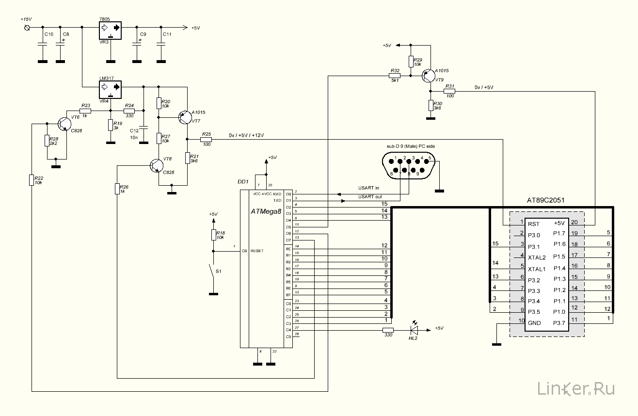
Простой программатор для AT89C2051 «на скорую руку» с использованием ATMega8
AT89C2051
ATMega8
Наконец внял просьбам в комментах и выкладываю всё, что относится к программатору AT89C2051, которым прошивал термометр из этого поста.
Схема, прошивка переделана с ATMega32 на ATMega8, сегодня проверено в железе еще раз, всё работает и шьётся. В программаторе за ненадобностью не реализованы функции Verify, Blank check и установка Lock bits. Функция Verify избыточна, т.к. проверка происходит по ходу записи.
В комплект поставки входит принципиальная схема программатора, проект для IAR с исходниками (на C) и сама прошивка для ATMega8, проект в IntelliJ Idea с исходниками программатора (на Java).
Обмен программатора с компьютером происходит через последовательный порт (USART in и USART out на схеме). Т.к. на моём комтьютере COM-портов нету, я использовал преобразователь RS232-USB, собранный на FT232RL (отсюда). Cкорость обмена с компьютером по COM-порту 9600-8n1.
Принципиальная схема контроллера
Исходный код прошивки
Прошивка
Фюзы для меги необходимо выставить следующие:
H-Fuse: 0xDD
L-Fuse: 0xE3
Частота внутреннего генератора при таких фюзах — 4MHz.
Прошивал мегу с помощью широко известного программатора USBasp софтом Khazama AVR Programmer.
Протокол программирования AT89C2051 описан в даташите, ссылка на который есть ниже.
Программатор
Архив с проектом программатора в IntelliJ Idea
Для работы с COM-портом из программы на Java, необходимо использовать вот эту библиотеку. Инструкция по установки есть внутри в файле INSTALL.
Эта библиотека расчитана на работу в 32-bit среде Java, поэтому на 64-bit Windows надо отдельно ставить 32-bit Java и запускать из-под неё, иначе будем получать сообщение «Can’t load IA 32-bit .dll on a AMD 64-bit platform thrown while loading gnu.io.RXTXCommDriver».
Дисклаймер: Всё это добро предлагается «как есть», Автор не отвечает за полную или частичную неработоспособность изделия, не берет на себя никаких обязательств по поддержке или развитию проекта. На вопросы буду отвечать по мере возможности и при наличии свободного времени.
Готовый JAR с зависимостями можно скачать здесь
Даташиты
- Микропроцессор AT89C2051 скачать
- Микропроцессор ATMega8 скачать
ceptimus
The Atmel AT89C2051 is a low cost microcontroller in a 20-pin DIL package. It runs MCS-51 (commonly termed ‘8051’) code. It works from 2.7V to 6V at anything from 0 Hz up to 24 MHz. It has 2K bytes of Flash memory to hold the program and 128 bytes of RAM. It has 15 I/O lines, a UART, an analogue comparator and two 16-bit timer/counters.
I came across the chip as it’s often used in cheap 7-segment clock kits such as this one from BangGood (only £2.71 at the time of writing).

I wanted to reprogram the chip so I could use the kit as a stopwatch/timer instead of a regular clock. Of course I could have bought a programmer to do the job, but reading the chip’s data sheet it seemed straightforward to do the programming with an Arduino – and I thought it would be a fun project to do that.
The chip is programmed a byte at a time by setting up each byte on 8 of the chip’s I/O lines and then pulsing some of the other I/O lines to ‘burn’ the byte to flash memory and move on to the next byte to be programmed. You can also read the existing program out of a chip (unless a read-protect bit has been set) and there are special ways of pulsing the I/O lines to erase the whole chip and so on.
The only tricky thing is that one pin has to be raised from the nominal operating voltage of five volts up to twelve volts during programming – the challenge was working out the easiest way to do this using an Arduino.
So I decided to use an Arduino Mega 2560 for this project. A Uno doesn’t have quite enough I/O to do the job properly, and the Mega 2560’s double row of I/O pins makes routing the connections to the chip simple as the chip can sit directly over the double-row connector.
I decided to use a charge pump (voltage multiplier) running off the Arduino’s five volts to generate the programming voltage – that seemed cleaner than needing a separate twelve volt supply. It just uses a few diodes and capacitors and relies on the Arduino pulsing some of its I/O lines to drive the voltage multiplier. A couple of zener diodes clip the voltage down to exactly 5V or 12V and a couple of transistors, also switched by the Arduino, select between either of those voltages or 0V to drive the pin on the chip.
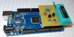
I designed a PCB using the free KiCad package. Here’s a .pdf of the circuit diagram, and here is what KiCad produces as a picture of the design. In the picture it looks like the chip to be programmed is soldered straight into the board, but of course in reality a ZIF socket is fitted in that position so that the chip(s) you are programming can be quickly swapped.
 That picture wrongly shows the tracks on the top of the board – I design them that way for home production as the transfer process mirror-images the tracks so that they’re correct for the back of the board. If you fancy making one of your own, it would be quite straightforward to do it on strip board – like I say most of the pins of the chip just connect direct to the Arduino pins that the chip sits over. If you want to etch your own PCB, here is a .pdf of the mask.
Here are a couple of snaps of the prototype board. You can see I didn’t bother to crop back the board edges!
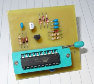
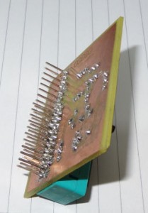 And this is what it looks like when docked on top of the Arduino Mega 2560.
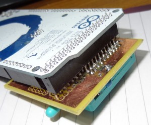 So that’s about it for the hardware. I’ll make a separate post about the Arduino sketch that does the work of programming the chip, and the PC program that talks to the Arduino to send and receive hex files.
Alok Menghrajani
Previously: security engineer at Square, co-author of HackLang, put the ‘s’ in https at Facebook. Maker of CTFs.
Programming an at89s4051 with an Arduino
I decided to flash an Atmel at89s4051 microcontroller using an Arduino. People have used the Arduino as a programmer in the past, but I didn’t find detailed information for programming this specific Atmel, so I did things mostly from scratch (only way to really learn how things work anyways).
I picked the at89s4051 mostly because people before me had picked it for their projects, such as the heart kit (i.e. I had a bunch lying around). The at89s2051 is exactly the same as the 4051, except it has 2Kb of flash memory instead of 4Kb).
I enjoy playing with microcontrollers because the code runs directly on the hardware, there’s usually no operating system.
The hardware
The at89s4051 costs about a dollar and is based on the 8051 instruction set (developed by Intel in 1981). The microcontroller has 15 I/O lines, two timers, analog comparators, PWM and UART; sounds very similar to an Arduino, right? The chip is fully static and can take a clock between 0 and 24Mhz.
If you want to program you own microcontroller, you can pick almost any chip. You can choose from a variety of architectures such as the 8051, PIC, AVR, ARM, etc. The chips usually cost between a few cents to a few dollars (as long as you stay away from the fancy stuff).
Note: I also had a few C variants lying around (at89c2051 and at89c4051). The C variants have the same pin layout but are not as easy to program due to the lack of ISP.
Besides the microcontroller, I used the Ultimate Arduino Microcontroller Pack. The useful components from the pack for this project were the Arduino UNO (you can pick any Arduino variant), breadboard (I used the small stamp sized one for fun), resistors, push button, LEDs and jumper wires. It;s cheaper to buy exactly the parts you need but having a starter kit is very convenient.
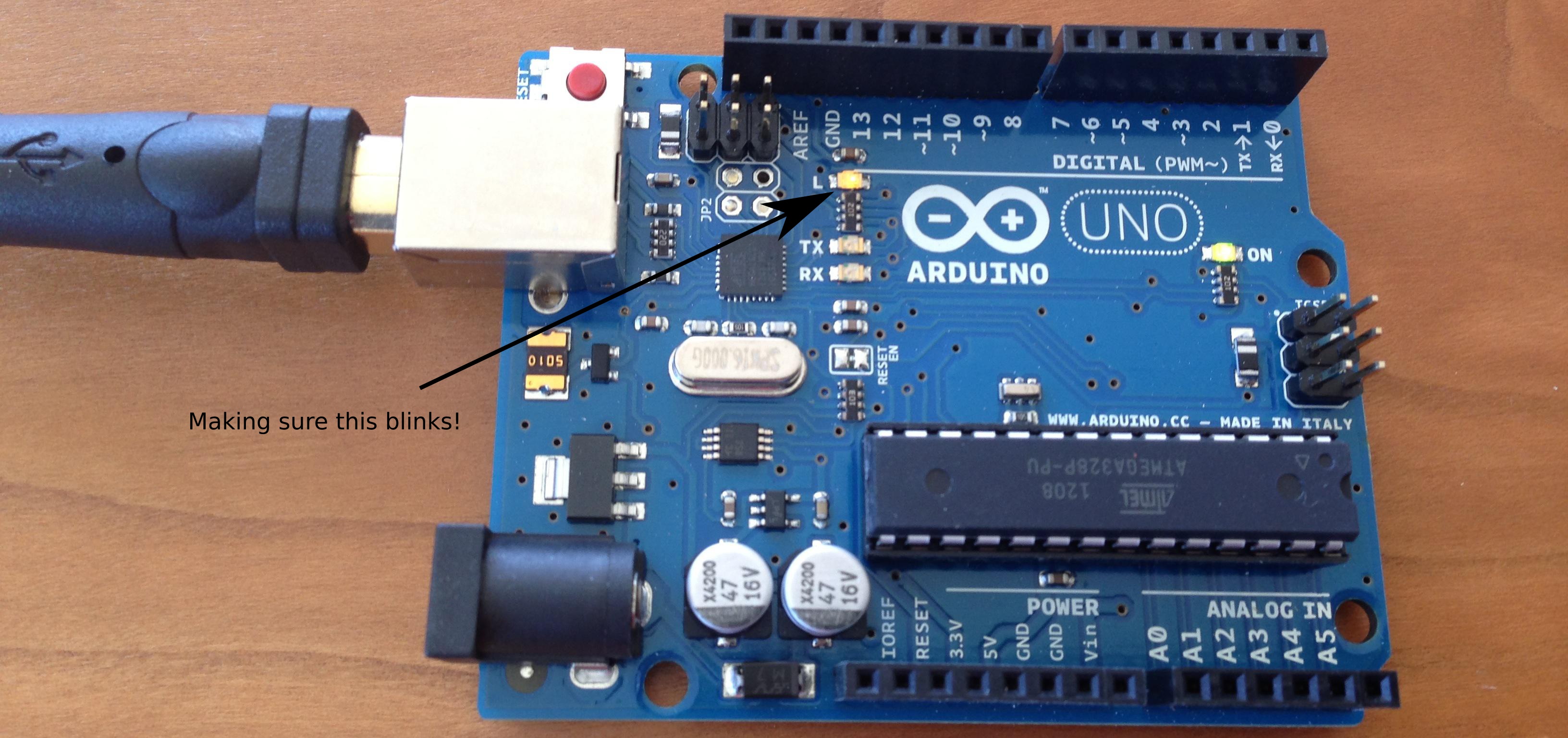
Making sure the Arduino works
The first step is to make sure the Arduino works. The exact installation process is beyond the scope of this article. I connected the Arduino to my laptop, installed the software and selected one of the samples (Blink). After uploading the code to the Arduino, I had a the onboard LED (which soldered with port 13) that was blinking every second:
Programming modes
The at89s4051 has two programming modes: parallel and ISP. In parallel mode, you need to power the chip with a 5V input (Vcc) but use a 12V signal on the RST/Vpp pin. Having to deal with two different voltage levels on the same pin is a little annoying (can be accomplished with a transistor). I decided to use the slower ISP programming mode.
In ISP mode, you set RST to 5V and then use SCK and MOSI to write data (one bit at a time) or SCK and MISO to read data (also one bit at time). It’s a very simple protocol and since SCK tells the microcontroller when the data is ready, you can flash the memory at any speed you desire. You can even use a switch to program it manually!
When programming in ISP mode, you need to provide a clock signal to XTAL1. The documentation says 3-24 Mhz. As far as I can tell, this range is very conservative. I was able to use a signal in the 500hz range. The final code uses 8Mhz. You can also use a crystal with two capacitors.
Keep in mind the chip erase function (which resets the content of the flash) needs to be called before being able to re-program the memory. I was expecting to be able to write to specific locations in the flash without having to clear the entire memory.
Hand assembling a small program
I wrote the following piece of assembly code to blink a LED connected to P3.0.
I then hand assembled this code (it’s only 24 bytes) and computed the relative offsets for the five jumps:
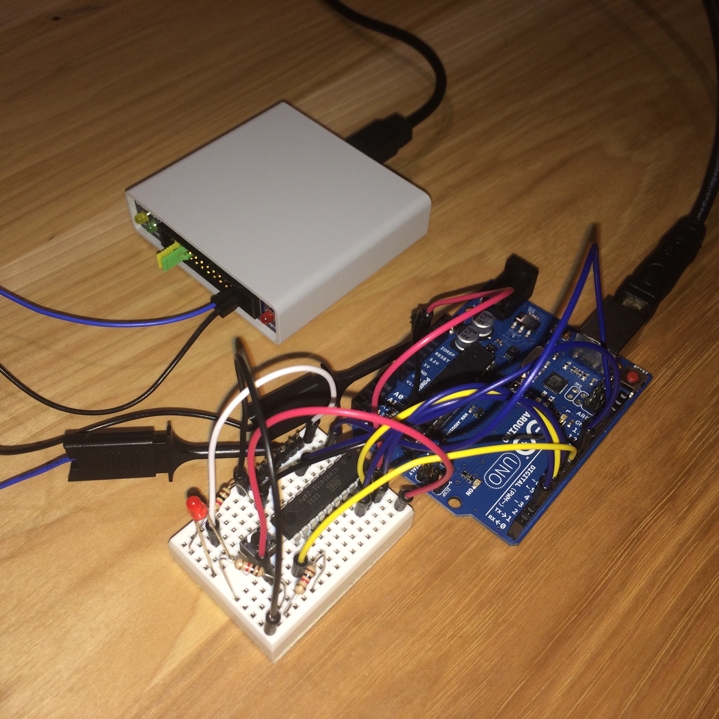
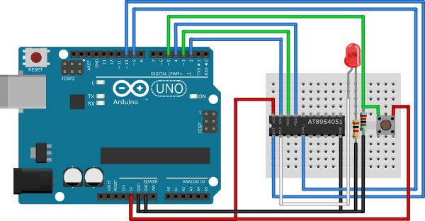
Connecting the microcontroller
The microcontroller is powered by the Arduino. I generally avoid using pins 0 and 1 on the Arduino because they are shared with the serial console on the UNO.
| Arduino | at89s4051 |
| 5V | pin 20 (Vcc) |
| GND | pin 10 (GND) |
| pin 2 | pin 19 (SCK) |
| pin 3 | pin 18 (MISO) |
| pin 4 | pin 17 (MOSI) |
| pin 9 (PWM) | pin 5 (XTAL1) |
| pin 11 (RST) | pin 1 (RST/VPP) |
| pin 2 is connected to a LED + 1kΩ resistor in series | |
| pin 5 is connected to a push button + 2kΩ pull-down resistor |
Ideally, you should use pull up resistors (and also a capacitor between VCC and GND to stablize the power). I however decided to just connect the pins, it works well enough for my use-case.
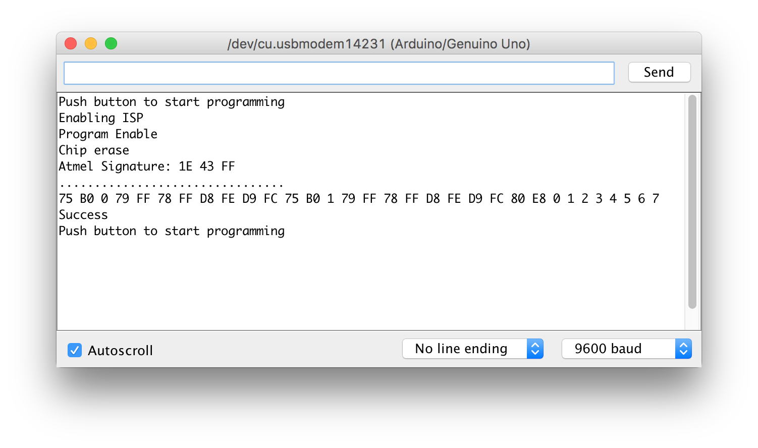
The code
Here is the full Arduino code:
Screenshots
Programming is really fast, takes a second or two.
I used a BitScope oscilloscope to check the XTAL1 signal. The square wave starts to get deformed at this speed.