Measuring DC Voltage using Arduino
Created on: 23 May 2013
Arduino analog inputs can be used to measure DC voltage between 0 and 5V (on 5V Arduinos such as the Arduino Uno when using the standard 5V analog reference voltage).
The range over which the Arduino can measure voltage can be increased by using two resistors to create a voltage divider. The voltage divider decreases the voltage being measured to within the range of the Arduino analog inputs. Code in the Arduino sketch is then used to calculate the actual voltage being measured.
This allows voltages greater than 5V to be measured.
This video shows the Arduino being used to measure various voltages:
—>
Principle of Operation
Input Impedance
A digital multimeter set to measure DC voltage will typically have an input impedance of 10MΩ or greater.
What this means is that the resistance between the two multimeter probes is 10MΩ or more.
A high input impedance for a voltmeter (or multimeter on the voltage scale) is desirable as the higher the input impedance, the less likely the multimeter will influence or change the circuit being measured.
Measuring voltage across a component in a circuit with a multimeter that has an input impedance of 10M ohms, is the same as connecting a 10M ohm resistor across the component.
If a voltmeter has a low input impedance, say 10kΩ and a voltage across a 10kΩ resistor is being measured, the multimeter is effectively changing the resistor value to 5kΩ (two 10k resistors in parallel = 5k resistance). The multimeter therefore has changed the circuit and possibly the voltage being measured.
So a high input impedance is desirable in our voltage divider circuit if the impedance of this «voltmeter» is going to influence the circuit being measured.
As a general rule though, a high input impedance device will generally pick up more noise or interference (EMI) than a low input impedance device.
Voltage Divider Circuit
A voltage divider circuit consisting of two resistors in series will divide the input voltage to bring it within the range of the Arduino analog inputs.
The circuit shown below will divide the input voltage by 11 (from the battery as the example input voltage being measured).
The circuit with the particular values shown has an input impedance of 1MΩ + 100kΩ = 1.1MΩ and is suitable for measuring DC voltages up to about 50V.
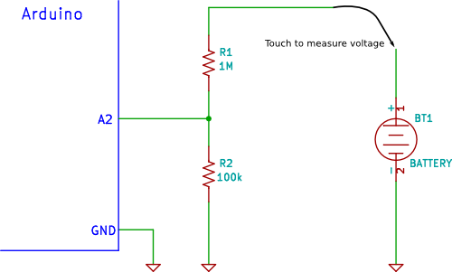 Arduino Voltage Divider Circuit Diagram
Precautions
Common Ground
If the Arduino is powered from an external power supply or a USB cable (i.e. not powered by a isolated battery or other isolated power supply) the circuit may share a common ground or 0V connection with the circuit under test.
If the GND connection of the Arduino is connected to any other part of the circuit under test except GND, then this is the same as shorting that part of the circuit to GND.
The GND of the Arduino is like the negative or common (COM) lead of a multimeter, except that it should be considered to be permanently connected to the GND of the circuit under test for safety, unless the Arduino or the circuit under test is completely isolated and «floating».
Input Protection
The resistor values in the circuit diagram above provide some over-voltage protection when measuring low voltages such as 5V, 9V or 12V. So if a voltage of say 30V is accidentally measured, it will not blow the Arduino analog input pin.
Any voltage higher than about 55V could damage the Arduino. The point on the resistor divider network connected to the the Arduino analog pin is equivalent to the input voltage divided by 11, so 55V ÷ 11 = 5V. In other words, when measuring 55V, the Arduino analog pin will be at its maximum voltage of 5V.
Providing this basic over-voltage protection is at the expense of not using the full 10-bit range of the analog input ADC if only lower voltages are to be measured, but changes of about 0.054V can still be measured.
No other protection for voltage spikes, reverse voltage or voltages higher than 55V is shown in the circuit.
You can help the Starting Electronics website by making a donation:
Any donation is much appreciated and used to pay the running costs of this website. Click the button below to make a donation.
Arduino Voltage Measuring Sketch
The sketch below reads the value on pin A2 of the Arduino. It provides some simple filtering by adding up 10 analog values from pin A2 sampled at 10ms intervals.
After taking 10 samples, the voltage is calculated using the average of the 10 sample values and sent out of the serial port for display on the Arduino Serial Monitor window.
Note that calibrated values are used in this sketch – these will need to be changed for your particular reference voltage and actual resistor division factor, explained below.
How the Code Works
Ten analog samples are taken using the following code:
The sum or total of all 10 values added together are stored in sum. The variable sample_count keeps track of the number of samples.
Both variables are reset after calculating and displaying the voltage:
The number of samples taken can be changed at the top of the sketch:
Don’t make this value too high or the sum of all the samples will be too big to fit in the sum variable.
The voltage is calculated using:
A calibrated value is used in place of 5.0 in the above sketch – calibration is explained later.
The 10 samples (sum) is divided by 10 (NUM_SAMPLES) to get the average value read.
5.0 is the 5V ADC reference voltage. 1024.0 is the maximum value that the ADC can have plus 1 (1023 + 1 or 2 to the power of 10 plus 1) 1023.0 can also be used here.
This calculates the divided voltage – i.e. the voltage on the A3 pin.
The actual voltage is calculated by multiplying the divided voltage by the division factor from the voltage divider network:
The above line of code calculates the actual voltage and then sends it out the serial port for display in the serial monitor window.
The sketch uses a calibrated value instead of 11.0 as shown here.
Books that may interest you:
Calibrating the Arduino and Circuit
A more accurate voltage could be obtained by using a precision reference voltage for the ADC and using 1% tolerance resistors or better.
Another way to obtain a more accurate reading is to calibrate the circuit. Calibration can be done by measuring the actual value of the reference voltage and the actual values of the voltage divider resistors. These values can then be used in the calculations in the Arduino sketch code.
Each Arduino and set of resistors would need to be individually calibrated because the voltage from the 5V regulator and the resistance of the voltage divider resistors will probably be slightly different for each Arduino and set of resistors.
Performing the Calibration
To perform the calibration, you will need a multimeter.
Calibrating the ADC Reference Voltage
First measure the 5V on the Arduino from the regulator (found on the Arduino 5V pin). This voltage is used for the Arduino ADC reference voltage by default.
Now put the measured value into the sketch as follows.
In the above example, the voltage measured on the 5V Arduino pin was 5.015V.
You can help the Starting Electronics website by making a donation:
Any donation is much appreciated and used to pay the running costs of this website. Click the button below to make a donation.
Calibrating the Resistor Network
Connect a stable power supply, such as a 9V battery across the resistor network. Measure the voltage across both resistors together i.e. measure the battery voltage.
Now measure the voltage across the 100k resistor (R2) i.e. between Arduino pin A3 and GND.
The voltage divider factor is calculated by dividing the first voltage by the second voltage or:
dividing factor = input voltage ÷ output voltage
For example, if the first or input voltage measured is 10.02V and the second or output voltage is 0.9V, then the division factor is:
10.02 ÷ 0.9 = 11.133
Now use this value in the Arduino sketch code:
If calibration is used, then 5% tolerance resistors can be used for the voltage divider.
Voltage Measurement Using Arduino

Introduction: Voltage Measurement Using Arduino


Measuring voltage is quite easy using any microcontroller as compared to the measurement of current. Measuring voltages becomes necessary if you are working with batteries or you want to make your own adjustable power supply. Though this method applies to any uC but in this tutorial, we will learn how to measure voltage using Arduino.
There are voltage sensors available in the market. But do you really need them? Let’s find out!
Step 1: Basics
A microcontroller cannot understand analog voltage directly. That is why we have to use an Analog to Digital Converter or ADC in short. Atmega328 which is the brain of the Arduino Uno has 6 channel (marked as A0 to A5), 10-bit ADC. This means that it will map input voltages from 0 to 5V into integer values from 0 to (2^10-1) i.e. equal to 1023 which gives a resolution of 4.9mV per unit. 0 will correspond to 0V, 1 to 4.9mv, 2 to 9.8mV and so on till 1023.
Step 2: Measuring 0-5V
First, we will see how to measure voltage with a maximum voltage of 5V. This is very easy as no special modifications are required. To simulate the varying voltage, we will use a potentiometer whose middle pin is connected to any one of the 6 channels. We will now write the code to read the values from ADC and convert them back into useful voltage readings.
Reading the analog pin A0
Now, the variable ‘value’ contains a value between 0 to 1023 depending upon the voltage.
The obtained value is now multiplied by the resolution (5/1023 = 4.9mV per unit) to get the actual voltage.
And finally, display the measured voltage on the Serial monitor.
Attachments
Step 3: Measuring Voltage Above 5V
But the problem arises when the voltage to be measured exceeds 5 volts. This can be solved using a voltage divider circuit which consists of 2 resistors connected in series as shown. One end of this series connection is connected to the voltage to be measured (Vm) and the other end to the ground. A voltage (V1) proportional to the measured voltage will appear at the junction of two resistors. This junction can then be connected to the analog pin of the Arduino. The voltage can be found out using this formula.
V1 = Vm * (R2/(R1+R2))
The voltage V1 is then measured by the Arduino.
Step 4: Building the Voltage Divider
Now to build this voltage divider, we first need to find out the values of resistors. Follow these steps to calculate the value of resistors.
- Determine the maximum voltage which is to be measured.
- Decide a suitable and standard value for R1 in kilo-ohm range.
- Using formula, calculate R2.
- If the value of R2 is not (or close to) a standard value, change R1 and repeat the above steps.
- Since Arduino can handle a maximum of 5V, V1 = 5V.
For example, Let the maximum voltage (Vm) to be measured be 12V and R1 = 47 kilo-ohms. Then using the formula R2 comes out to be equal to 33k.
Now, Build a voltage divider circuit using these resistors.
With this setup, we now have an upper and lower limit. For Vm = 12V we get V1 = 5V and for Vm = 0V we get V1 = 0V. That is, for 0 to 12V at Vm, there will be a proportional voltage from 0 to 5V at V1 which can then be fed into the Arduino as before.
Step 5: Reading the Voltage
With a slight modification in the code, we can now measure 0 to 12V.
Analog value is read as before. Then, using the same formula mentioned previously, the voltage between 0 and 12V is measured.
The commonly available Voltage Sensor Modules are nothing but just a voltage divider circuit. These are rated for 0 to 25V with 30 kiloohm and 7.5 kilo-ohm resistors.
So, Why to BUY, when you can DIY!
Thank you for sticking till the end. I hope that this tutorial would have helped you.
Subscribe to my YouTube channel for more upcoming projects and tutorials. Thanks once again!
Attachments
2 People Made This Project!


Did you make this project? Share it with us!
Recommendations


Cheese Challenge

Back to School: Student Design Challenge

Plywood Contest

22 Comments

Question 1 year ago
I want to measure electricity below 200v, is this okay?


Answer 1 year ago
Yes it will. As long as your voltage divider creates a value equal to or below 5 volts. In your case your voltage divider is (1/40) and would produce 5 volts with a 200 volt input.
One way to protect your micro controller is to add a zener diode, with a 5 volt breakdown, in parallel to R2. This will protect your micro controller if voltages above 200 volts are input into the circuit.