Arduino — LED — Blink
In this tutorial, we learn how to control LED with using Arduino, how to program for Arduino to turn LED on/off, and how to blink LED
Hardware Required
| 1 | × | Arduino UNO or Genuino UNO |
| 1 | × | USB 2.0 cable type A/B |
| 1 | × | LED |
| 1 | × | 220 ohm resistor |
| 1 | × | Breadboard |
| 2 | × | Jumper Wires |
About LED
Pinout
LED includes two pins:

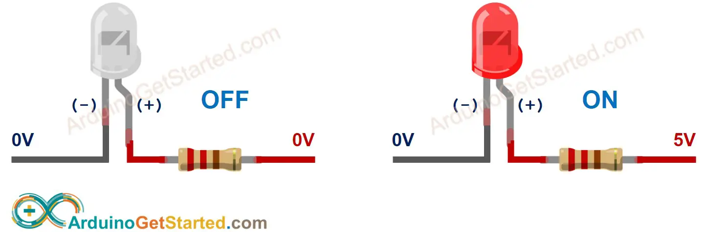
How It Works
After connecting the cathode(-) to GND :
Besides, if generating a PWM signal to the anode(+), the brightness of LED is changed according to PWM value ( described in detail in this tutorial)
Arduino — LED
When an Arduino’s pin is configured as a digital output, the pin’s voltage can be programmatically set to GND or VCC value.
By connecting the Arduino’s pin to LED’s anode(+) pin (via a resistor), we can programmatically control LED’s state.
Wiring Diagram
We are going to run through two examples:
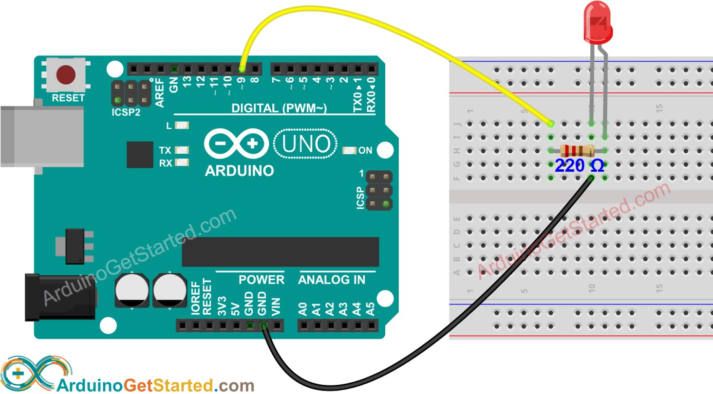
Image is developed using Fritzing. Click to enlarge image
How To Program
Arduino Code
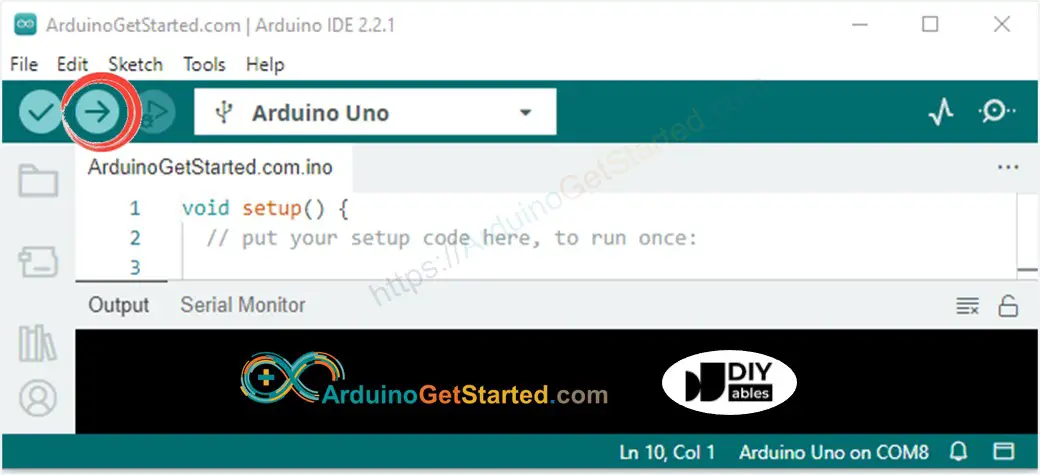
Quick Steps
Code Explanation
Read the line-by-line explanation in comment lines of code!
The above code uses the delay () . This function blocks Arduino from doing other tasks during the delay time. If your project requires to do some tasks, avoid blocking Arduino by using the non-blocking method for Arduino.
Modifying Arduino Code
Modifying code to control the external LED
Quick Steps
This tutorial provides in-depth knowledge that helps you understand the working principle. To make it easy, you can use Arduino — LED library.
Video Tutorial
We are considering to make the video tutorials. If you think the video tutorials are essential, please subscribe to our YouTube channel to give us motivation for making the videos.
Challenge Yourself
Additional Knowledge
At a time, one pin can take only one task. If you already used a pin for another task (e.g, digital input, analog input, PWM, UART. ), you should NOT use it as digital output to control LED. For example, if we use Serial.println() function, we should NOT use pin 0 and 1 for any other purpose because these pins are used for Serial.
Extendability
This tutorial shows how to use the output pin of Arduino to control an LED. We can apply this code to control ON /OFF any devices, even big machines.
for devices/machines that use a high power supply ( > 5v) and/or high-current consumption, we need to use a relay between output pin and devices/machines — see Arduino — Relay.
LED on Commercial Products
Small LEDs usually are used to indicate the status of devices. For examples:
Arduino Lesson 1. Blink
Overview
New Subscription
Please sign in to subscribe to this guide.
You will be redirected back to this guide once you sign in, and can then subscribe to this guide.

Parts


The ‘L’ LED
The Arduino has rows of connectors along both sides that are used to connect to electronic devices and plug-in ‘shields’ that allow the Arduino to do more.
However, the Arduino also has a single LED that you can control from your sketches. This LED is built onto the Arduino board and is often referred to as the ‘L’ LED as this is how it is labelled on the board.
The position of this LED is circled in red on the pictures of the Arduino Uno and Leonardo below.


Loading the ‘Blink’ Example
You may find that your Arduino board’s ‘L’ LED already blinks when you connect it to a USB plug. This is because Arduino boards are generally shipped with the ‘Blink’ sketch pre-installed.
In this lesson, we will reprogram the Arduino with our own Blink sketch and then change the rate at which it blinks.
In Lesson 0, you setup your Arduino IDE and made sure that you could find the right serial port for it to connect to your Arduino board. The time has now come to put that connection to the test and program your Arduino board.
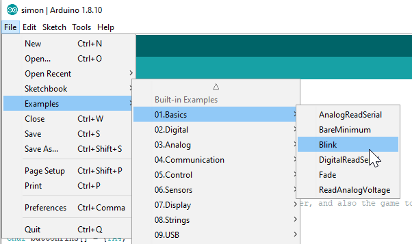
The Arduino IDE includes a large collection of example sketches that you can load up and use. This includes an example sketch for making the ‘L’ LED blink.
Load the ‘Blink’ sketch that you will find in the IDE’s menu system under File → Examples → 01.Basics


Saving a Copy of ‘Blink’
The example sketches included with the Arduino IDE are ‘read-only’. That is, you can upload them to an Arduino board, but if you change them, you cannot save them as the same file.
We are going to change this sketch, so, the first thing you need to do is save your own copy that you can change however you like.
From the File menu on the Arduino IDE select the option ‘Save As..’ and then save the sketch with the name ‘MyBlink’.


Uploading Blink to the Board
Attach your Arduino board to your computer with the USB cable and check that the ‘Board Type’ and ‘Serial Port’ are set correctly. You may need to refer back to Lesson 0.
The Arduino IDE will show you the current settings for board at the bottom of the window.


The clue is at the top here, it probably means that your board is not connected at all, or the drivers have not been installed (if necessary) or that the wrong serial port is selected.
If you get this, go back to Lesson 0 and check your installation.
Once the upload has completed, the board should restart and start blinking.
How ‘Blink’ Works
The first thing to note is that quite a lot of this sketch is what is called ‘comments’. Comments are not actual program instructions, they are just comments about how the program works. They are there for out benefit, so that there is some explanation to accompany the sketch.
Everything between /* and */ at the top of the sketch is a block comment, that explains what the sketch is for.
There are also single line comments that start with // and everything up intil the end of the line counts as being a comment.
The first actual line of code is:
Every Arduino sketch must have a ‘setup’ function, and the part of it where you might want to add instructions of your own is between the < and the >.
In this case, there is just one command there, which, as the comment states tells the Arduino board that we are going to use the LED pin as an output.
It is also mandatory for a sketch to have a ‘loop’ function. Unlike the ‘setup’ function that only runs once, after a reset, the ‘loop’ function will, after it has finished running its commands, immediately start again.
Blink
This example shows the simplest thing you can do with an Arduino to see physical output: it blinks the on-board LED.
Hardware Required
220 ohm resistor
Circuit
This example uses the built-in LED that most Arduino boards have. This LED is connected to a digital pin and its number may vary from board type to board type. To make your life easier, we have a constant that is specified in every board descriptor file. This constant is LED_BUILTIN and allows you to control the built-in LED easily. Here is the correspondence between the constant and the digital pin.
D13 — Intel Edison
D13 — Intel Galileo Gen2
D13 — Leonardo and Micro
D13 — LilyPad USB
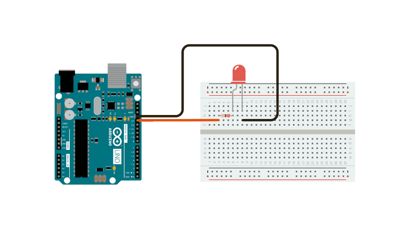
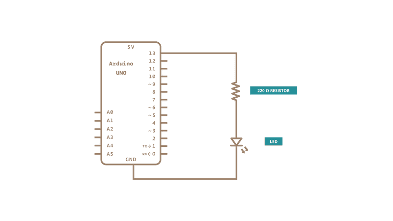
If you want to lit an external LED with this sketch, you need to build this circuit, where you connect one end of the resistor to the digital pin correspondent to the LED_BUILTIN constant. Connect the long leg of the LED (the positive leg, called the anode) to the other end of the resistor. Connect the short leg of the LED (the negative leg, called the cathode) to the GND. In the diagram below we show an UNO board that has D13 as the LED_BUILTIN value.
The value of the resistor in series with the LED may be of a different value than 220 ohm; the LED will lit up also with values up to 1K ohm.
Schematic
After you build the circuit plug your Arduino board into your computer, start the Arduino Software (IDE) and enter the code below. You may also load it from the menu File/Examples/01.Basics/Blink . The first thing you do is to initialize LED_BUILTIN pin as an output pin with the line
In the main loop, you turn the LED on with the line:
This supplies 5 volts to the LED anode. That creates a voltage difference across the pins of the LED, and lights it up. Then you turn it off with the line:
That takes the LED_BUILTIN pin back to 0 volts, and turns the LED off. In between the on and the off, you want enough time for a person to see the change, so the delay() commands tell the board to do nothing for 1000 milliseconds, or one second. When you use the delay() command, nothing else happens for that amount of time. Once you’ve understood the basic examples, check out the BlinkWithoutDelay example to learn how to create a delay while doing other things.
Once you’ve understood this example, check out the DigitalReadSerial example to learn how read a switch connected to the board.
See Also
AnalogReadSerial — Read a potentiometer, print its state out to the Arduino Serial Monitor.
BareMinimum — The bare minimum of code needed to start an Arduino sketch.
DigitalReadSerial — Read a switch, print the state out to the Arduino Serial Monitor.
Fade — Demonstrates the use of analog output to fade an LED.
ReadAnalogVoltage — Reads an analog input and prints the voltage to the serial monitor.
5 Ways to Blink an LED with Arduino
Learn about the internals of the Arduino Uno microcontroller by looking at 5 different approaches for a seemingly simple task: blinking an LED!
Uri Shaked
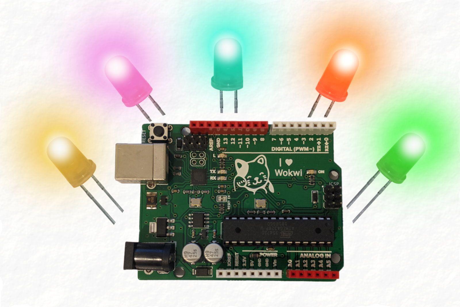
Blinking an LED is the «Hello World» program of hardware. It is also one of the most popular Arduino program, and I bet electronics enthusiast has run it at least once in their life.
In this blog post, I am going to show you 5 different ways of blinking an LED on Arduino: blinking an LED by turning it on/off roughly once a second.
We’ll start with the LED Blink example that comes with the Arduino IDE:
 5 ways to toggle an LED using Arduino
Below is the code for blinking an LED with standard built in example:
5 ways to blink an LED in Arduino — using standard example
This is pretty straightforward: LED_BUILTIN is a constant that contains the number of the pin connected to the on-board LED, pin 13 in Arduino Uno. We set this pin to output in the setup() function, and then repeat the following code:
- Set the pin to HIGH (5V), this will turn the LED on.
- Wait for 1000 milliseconds, or one second.
- Set the pin to LOW (0V), cutting the power to the LED and turning it off.
- Wait for another second, and then repeat everything again.
Can we achieve the same with less code?
The Two-Liner
We can easily cut the loop() code in the LED blink program down to two lines by toggling the value of the pin:
5 ways to blink an LED in Arduino — using inversion operator
Here’s the trick: digitalRead() returns the current output value of the pin: 1 if the pin is high and the LED is on, 0 otherwise. We use the ! (not) operator to invert that value, and thus toggle the state of the LED. So basically the code above could be read as:
- Toggle the state of the LED.
- Wait one second, repeat.
The One-Liner
This is my favorite one, which was first presented to me by my friend Avi Ostfeld. By using a clever trick, we no longer need to call delay() in our code to blink the LED using Arduino. The one-liner code to toggle the LED is shown below:
5 different ways to toggle an LED using Arduino — using one line of code
We take advantage of Arduino’s millis() function, which returns the number of milliseconds since the program has started running. We then divide this value by 1000, so we get the number of seconds passed so far. Finally, we take the number of seconds and calculate the remainder of dividing it by two, using the modulus ( % ) operator. This calculation returns 0 for even numbers and 1 for odd numbers:
In other words, we repeatedly take the number of seconds passed since the program started running, and set the value of the LED based on that: ON if the number if currently odd, OFF if it is currently even. This is how we achieve the desired blink.
This solution of not using delay() has a big advantage over the previous approaches to toggle an LED: we can perform additional tasks inside our loop, as it is no longer blocking on the delay() function. For example, you can blink three LEDs in different intervals: one every second, one every 1.26 seconds, and one every 380 milliseconds. Can you write the code for that?
Blinking with Timers ⌚
Our solutions to blink an LED with Arduino so far relied on Arduino’s built-in functions, so they would virtually work on any board supported by the Arduino environment. However, if we focus just on the Uno board, we can start taking advantage of its specific hardware features — namely, timers and interrupts.
Hardware timers in Arduino are simply counters that go up every predetermined interval. This interval is usually tied to the clock speed of the microcontroller. Uno boards use the ATmega328 microcontroller, and run it with a clock speed of 16 MHz, or 16 million times per second.
The following code sets up one of Arduino’s hardware timers and uses it to toggle the LED roughly every second:
5 different ways to toggle an LED on Arduino — using hardware timers
You probably noticed a few weird things here. First of all, our loop() function is empty, is the Uno doing nothing? Second, what are all these strange acronyms: OVF, ISR, TCCR1A, etc.?
For starters, here is some more background about the Uno timers. It has 3 timers, numbered 0 to 2. Timer0 and Timer2 are 8-bit timers, so they count from 0 to 255, Timer1 , on the other hand, is a 16-bit timer, so it counts from 0 to 65535: