Сканер штрих и QR-кодов: подключение и режимы работы
Используйте сканер баркодов для считывания штрихкодов и QR-кодов. Автоматизируйте складской учёт или притворитесь кассиром супермаркета, чтобы пропикать все товары!
Режим виртуальной USB-клавиатуры
Сканер штрихкодов работает напрямую с компьютером без всяких приложений: он притворяется типовой USB-клавиатурой и выдаёт считанные данные в виде строки текста. Именно такой режим работы задан по умолчанию.
Режим работы через COM-порт
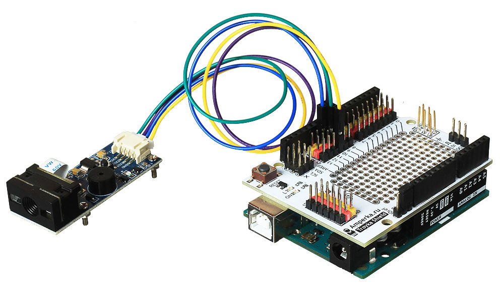
Barcode сканер общается с управляющей платой по протоколу UART. В зависимости от управляющей платформы выберите вариант подключения.
HardwareSerial
На управляющей плате Iskra JS и Arduino платах с микроконтроллером ATmega32U4 / ATSAMD21G18 , интерфейс UART выведен на контактные пины, а данные по USB переедаются через виртуальный COM-порт. Это даёт возможность одновременно подключить Barcode-модуль к аппаратному UART и выполнять отладку по USB.
Список поддерживаемых плат:
Схема подключения
При подключении к платам формата Arduino R3 удобно использовать Troyka Shield. 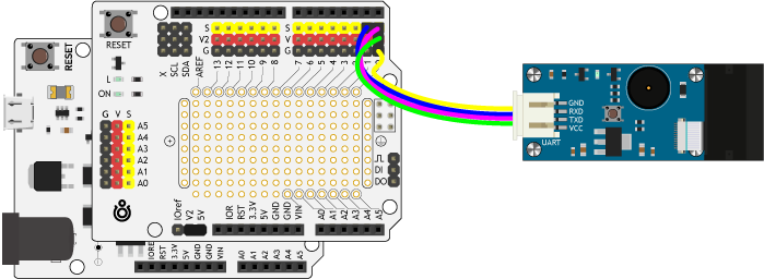
Исходный код
В качестве примера все сканированные штрихкоды выведем в консоль.
SoftwareSerial
На управляющих платформах Arduino с микроконтроллером ATmega328 / ATmega2560 , интерфейс UART выведен на контактные пины платы и он же используется для отладки по USB. Это означает невозможность использовать одновременно прошивку/отладку по USB и общение с Barcode-модулем. Решение проблемы — программный UART. Подключите пины TX и RX Barcode модуля к другим контактам управляющей платы и используйте библиотеку SoftwareSerial.
Схема подключения
Для примера подключим управляющие пины сканера TX и RX — на 10 и 11 контакты управляющей платы.
При подключении удобно использовать Troyka Shield. 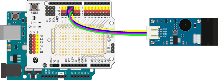
Исходный код
В качестве примера все сканированные штрихкоды выведем в консоль.
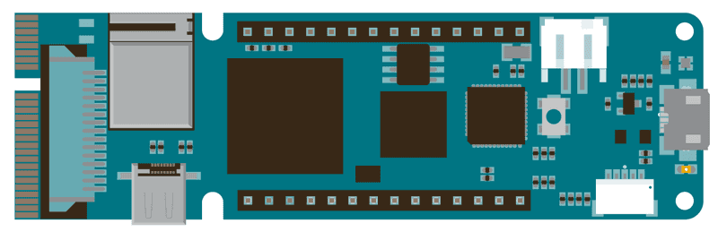
HardwareSerial Mega
На платформах форм-фактора Arduino Mega 2560 интерфейс UART выведен на контактные пины платы и он же используется для отладки по USB. Это означает невозможность использовать одновременно прошивку/отладку по USB и общение с Barcode-модулем.
Но на платах такого форм-фактора есть ещё дополнительно три аппаратных UART:
alvarowolfx/ESP32QRCodeReader
Use Git or checkout with SVN using the web URL.
Work fast with our official CLI. Learn more.
Launching GitHub Desktop
If nothing happens, download GitHub Desktop and try again.
Launching GitHub Desktop
If nothing happens, download GitHub Desktop and try again.
Launching Xcode
If nothing happens, download Xcode and try again.
Launching Visual Studio Code
Your codespace will open once ready.
There was a problem preparing your codespace, please try again.
Latest commit
Git stats
Files
Failed to load latest commit information.
README.md
ESP32 QR Code Reader
This library provides a interface to read QR Codes using an ESP32 with a camera.
Internally this lib uses a slight modified version of the Quirc library and some code from OpenMV port on the MaixPy project.
- EN-US — See demo video at https://twitter.com/alvaroviebrantz/status/1290116219199279104?s=20
- PT-BR — Veja video de demo em https://twitter.com/alvaroviebrantz/status/1290116405824806912?s=20
Is recommended to use PlatformIO to install this lib. Add ESP32QRCodeReader to your platformio.ini file.
From PlatformIO library:
Directly from Github:
This library comes with a number of example sketches. See File > Examples > ESP32QRCodeReader within the Arduino application. You can see them on the examples folder on this repository.
- Need an ESP32 module with PSRAM — See below.
The QR Code recognition lib required a lot of memory, so I was only able to get this to work with an ESP32 that has PSRRAM available and also the Quirc library is modified to use that directly.
- ESP32 module
- PSRAM Available
- Camera module — Tested with OV2640
ESP32 modules with camera that have PSRAM and should work:
- CAMERA_MODEL_WROVER_KIT
- CAMERA_MODEL_ESP_EYE
- CAMERA_MODEL_M5STACK_PSRAM
- CAMERA_MODEL_M5STACK_V2_PSRAM
- CAMERA_MODEL_M5STACK_WIDE
- CAMERA_MODEL_AI_THINKER
ESP32 modules without PSRAM that will not work:
This code is released under the MIT License.
QR Code Recognition
This example shows the flexibility and power of the FPGA architecture. A QR code recognition set of APIs is included in the VidorGraphics library and the corresponding IP is in the bitstream that is loaded in the FPGA together with the sketch for the SAMD core. The example highlights on video the QR code markers and prints on the serial monitor the coordinates of the markers found.
Hardware Required
Omnivision OV5647 camera
microHDMI to HDMI cable or adaptor
Monitor with HDMI input
Circuit
There is no circuit for this example.
Include the VidorCamera library, which is part of VidorGraphics. #include «VidorGraphics.h» #include «VidorCamera.h»
You have a number of functions available to manage the recognition of a QR Code. VidorQR is part of the VidorCam library; the functions are accessible with cam.qrrec.
void begin() — start recognition algorithm
void end() — stops recognition
void setMode(uint8_t mode); — change video mode
void setThr(uint8_t thr); — set recognition thresold
int readQRCode(void); — perform qr code recognition
sQrDet qr; — structure containing detected points
See Also
Enable Camera — Enables the video stream from a camera to an HDMI monitor
Draw Logo — Draw the Arduino Logo on an HDMI monitor
Encoder — Manage easily quadrature encoders and never lose an impulse
For more details on the Arduino MKR Vidor 4000, see the product page.
Generate a QR code using Arduino and display it on SSD1306 OLED

The «Quick Response» code or abbreviated as QR code has become an essential part of our digital lives, chances are that you’re already subconsciously familiar with them by now you’ve probably been roaming around your local grocery store, or maybe you are reading through your favourite book, or even possibly you are making an online payment with Google Pay, PhonePe or Paytm, or surfing the web, etc. (I suppose I could go on and on with examples huh?) and you happened to have come across this weird looking square thing and thought, what is this square thing anyway and if you haven’t. well, don’t worry it’s bound to happen sooner or later, so to understand the topic better we are going to do a fun little project with Arduino and OLED and demystify the following things:
- Basic Concept of the QR code.
- How it works.
- How to make your very own QR code using Arduino.
- And finally, display it in an OLED (SSD1306) screen.
So, What is this QR Code Anyway?
QR code (Quick Response code) is a matrix 2D code for reading data at high speed, developed by DENSO WAVE in 1994 for the automotive industry of Japan. A QR code compresses data very efficiently compared to the standard barcode, to achieve this it uses four standardized encoding modes (numeric, alphanumeric, byte/binary, and kanji), the technology was made «open source” i.e. available for everyone so, it gained popularity very rapidly. Significant advantages of QR Codes over conventional barcodes are larger data capacity and high fault tolerance.

How QR Code Works?
QR codes (and other data matrix codes) are designed to be read by special tools, not by humans, so there’s only a specific amount we can understand by studying visually, although every code is different in various ways though they contain a few interesting common features by observing the circuitdigest.com QR code we will study some of them
- Finder Patterns: Large square boxes with a solid box inside in the three corners of the code make it easy to confirm that it’s a QR code since there are only three of them, so it’s pretty obvious that in which way the code is oriented.
- Alignment Pattern: This makes it certain that whatever the orientation the code can be readable.
- Timing Pattern: This runs horizontally and vertically between the three finder patterns, using these lines the reader can determine the size of the code.
- Version Information: There are currently 40 different versions of the QR code standard, this section of the code determines the QR code version which is being used, for marketing version 1-7 used normally.
- Format Information: The format partners have information about error tolerance and data masking.
- Data Area: This section of the code contains all the data elements and error correction code along.
- Quit Zone: The spacing in every QR code is mandatory in order to differentiate the code from its surroundings.
The image below will give you a clear idea about the code

Other sections of the code are data and redundancy code.
There are a number of other features and complicated topics that I won’t be discussing in this tutorial, if you do like to read in more details about the QR code please follow this QR Code tutorial by Tan Jin Soon, EPCglobal Singapore Council. Synthesis Journal, 2008.
The Specification of the QR Code
TomasHubelbauer/arduino-qr
Use Git or checkout with SVN using the web URL.
Work fast with our official CLI. Learn more.
Launching GitHub Desktop
If nothing happens, download GitHub Desktop and try again.
Launching GitHub Desktop
If nothing happens, download GitHub Desktop and try again.
Launching Xcode
If nothing happens, download Xcode and try again.
Launching Visual Studio Code
Your codespace will open once ready.
There was a problem preparing your codespace, please try again.
Latest commit
Git stats
Files
Failed to load latest commit information.
readme.md
Arduino QR Code
An Arduino QR code display using a matrix of 8×8 LED dot matrix displays driven by the MAX7219 display driver.


The displays are chainable up to 8 displays in one chain. Multiple chains need to be used to drive more displays.
Arduino has 14 digital pins and 6 analog pins which can be used as digital. It can support up to 6 chains (3 SPI pins per chain: DIN, CLK and CS). That results in the maximum display size of 48×48 dots (6×6 displays to keep the QR square). This allows displaying QR codes of versions 1-7 or displaying a version 1 code at twice the size.
| Version | Pixels | Displays | Dots | Utilization |
|---|---|---|---|---|
| QR 1 | 21×21 (441) | 9 (3×3) | 24×24 (576) | 77 % (441/576) |
| QR 1 @2x | 42×42 (1764) | 36 (6×6) | 48×48 (2304) | 76 % (1764/2304) |
| QR 2 | 25×25 (625) | 16 (4×4) | 32×32 (1024) | 61 % (625/1024) |
| QR 3 | 29×29 (841) | 16 (4×4) | 32×32 (1024) | 82 % (841/1024) |
| QR 4 | 33×33 (1089) | 25 (5×5) | 40×40 (1600) | 68 % (1089/1600) |
| QR 5 | 37×37 (1369) | 25 (5×5) | 40×40 (1600) | 85 % (1369/1600) |
| QR 6 | 41×41 (1681) | 36 (6×6) | 48×48 (2304) | 72 % (1681/2304) |
| QR 7 | 45×45 (2025) | 36 (6×6) | 48×48 (2304) | 87 % (2025/2304) |
| QR | NH | NQ | NM | NL | ANH | ANQ | ANM | ANL |
|---|---|---|---|---|---|---|---|---|
| 1 | 17 | 27 | 34 | 41 | 10 | 16 | 20 | 25 |
| 2 | 34 | 48 | 63 | 77 | 20 | 29 | 38 | 47 |
| 3 | 58 | 77 | 101 | 127 | 35 | 47 | 61 | 77 |
| 4 | 82 | 111 | 149 | 187 | 50 | 67 | 90 | 114 |
| 5 | 106 | 144 | 202 | 255 | 64 | 87 | 122 | 154 |
| 6 | 139 | 178 | 255 | 322 | 84 | 108 | 154 | 195 |
| 7 | 154 | 207 | 293 | 370 | 93 | 125 | 178 | 224 |
| QR | 1 | 2 | 3 | 4 | 5 | 6 | 7 |
|---|---|---|---|---|---|---|---|
| NH | 17 | 34 | 58 | 82 | 106 | 139 | 154 |
| NQ | 27 | 48 | 77 | 111 | 144 | 178 | 207 |
| NM | 34 | 63 | 101 | 149 | 202 | 255 | 293 |
| NL | 41 | 77 | 127 | 187 | 255 | 322 | 370 |
| ANH | 10 | 20 | 35 | 50 | 64 | 84 | 93 |
| ANQ | 16 | 29 | 47 | 67 | 87 | 108 | 125 |
| ANM | 20 | 38 | 61 | 90 | 122 | 154 | 178 |
| ANL | 25 | 47 | 77 | 114 | 154 | 195 | 224 |
N = numeric, AN = alpha-numeric, H = high, Q = quartile, M = medium, L = low
See qr.ino for the WIP live Arduino code. Compared to the simulation below, it adds Bluetooth communication support and uses correct wiring to how the LED dot matrix displays I got behave, they seem to differ a bit from the simulated ones.
See wokwi.ino and diagram.json for the Wokwi simulation files. Compared to the live Arduino code above, there is no Bluetooth communication support.
Document my build of the 3×3 display grid
I build a 3×3 display grid and wired it up to an Arduino Uno. The wiring was a bit different from the Wokwi simulation.
- Include the real hardware wiring diagram
- Add photos+videos of the QR code in action including scanning screencast
- Document the HC-06 and HM-10 (MLT-BT05) difference (not BLE versus BLE)
- iOS seems to only support BLE (maybe BT 4.0) based Bluetooth serial modules
- Android supports only non-BLE with my Samsung A41 test phone and the app Arduino bluetooth controller
- Document https://www.arduino.cc/en/Reference/SoftwareSerial serial bridge
- Echo Bluetooth serial to serial data to debug in Arduino IDE Serial Monitor
- Echo serial to Bluetooth serial data to debug in BLExAR iOS app Console
- Document pins
Danila Loginov built a WebBluetooth terminal capable of talking to the HM-10/MLT-BT05 BLE module. It works for me in Chrome on macOS and using Bluefy on iOS.
It doesn’t work with the HC-06 Bluetooth 2.0/3.0 module. It seems WebBluetooth only supports Bluetooth 4.0/BLE since macOS itself did see both modules.
3D-print an enclosure to hold the 4×4 matrix of the displays together
Experiment with normal and inverted QR display to see what reads better
Await and try white dot-matrix displays to see if they scan better than red
I ordered a bunch of white dot matrix displays to see if they scan faster/more reliably.
See if I can make this work on the Raspberry Pi Pico using Wokwi Pico sim
The Pico can mount itself as a mass storage device, so the text file QR content source idea would be that much easier.
Verify LEDControl can truly only drive 8 dot matrix displays in a chain
Test this on actual hardware. Check other libraries too, to find whichever is able to control the most displays.
Test the method of using analog pins as digital on a real Arduino
According to Stack Overflow and the Wokwi simulation above, analog pins can be used as digital pins. If on real hardware this works, it bumps us from a 4×4 display to a 6×6 display.
Await EZ Expander delivery and try out layouts with more chains than 6
I’ve ordered 3 and they should arrive in a week or two.
14 digital pins — 3 used shield pins + 13 new shield pins + 6 analog pins = 30
If the chains are truly stuck at 8 displays at most, this would give us a 8×8 display, 64×64 dots, QR level up to 11 (61×61). Or QR version 3 at double size. Version 11 numeric capacity is 331-772 and alphanumeric 200-468.
If the chains could somehow be 10 displays long, that would give us a 10×10 display, 100×100 dots, QR level up to 20 (97×97). Or QR version 7, double sized. Version 20 numeric capacity is 919-2061 and alphanumeric 557-1249.
If the chains really need to be at most 8 displays, we could still achieve a 9×9 display by using 8 chains for an 8×8 display and then two chains for the 9th row and column. This would complicate the code calculations, but could be worth it. 9×9 is 72×72 dots, QR level up to version 13 (69×69). Or QR version 4, doubled. Version 13 numeric capacity is 427-1022 and alphanumeric 259-619.
Address code TODO comments
There are some improvement / new feature ideas in there.
Build a PCB to mount the LED dot matrix display grid and the Arduino on
Instead of attempting to squeeze the rat’s nest of wires into the 3d printed box or to use solder bridge connections between the displays to avoid the excessive amount of wires, let’s order a PCB where the driver boards could be mounted such that the display grid works out perfectly aligned and the Arduino could be held on the backside of the PCB, or even on the front side too in sort of a base.
Consider whether I want to have an on-board battery and a switch or if I’ll just run a USB cable out from the enclosure to connect into a powerbank.
Calculate approximate expected runtime on a battery
The load of this device is basically constant, so it should be doable to find an approximate duration I can expect this to last… and then verify it in the real world.
Trim the received message and further validate it if needed
At the very least, leading and trailing space could be removed. Perhaps length and fit into the QR code storage for the given level could be checked, too. The indication of an incorrect value could be the display grid going blank or blinking.
Print the processed message back into the Bluetooth serial console
To confirm the payload was set and how it was adjusted (trim, case).
Figure out why the mismatch with QR generator library (libraries?)
I found this QR generator online which allows controlling the level, too:
My QR codes scan, but they appear different from the ones generated by this lib. I should find out why that is to understand if I have any problems in my QR code setup.
Play around with the wokwi-logic-analyzer part to see the display driving
This is an undocumented part in Wokwi. It should be fun to hook it up to a single display and see the driving signals for things like lighting up the edge LEDs and clearing/filling the display. Maybe it will also reveal the difference between pushing in a single row/column as a single number/call in LEDControl and setting the individual LEDs. The output format of the logic analyzer is VCD, openable by PulseView (Open > Import Value Change Dump data).
Test whether using setRow / setColumn would be faster than setLed
The complexity of the code would increase if I were to use either of these methods, but if the performance improves, it might be justifiable. Although the current «rolling» animation is pretty pleasant to look at, so maybe fast refresh is not needed?
Add an OPT boot QR code wnich when scanned allows generating edit passwords
The thing starts up, presents a QR code, scanned by the Authenticator app on the phone, this OTP QR code can generate 6 digit codes which are then used to prefix the message in the Bluetooth control app such that messages which do not have this prefix are rejected and the QT code shown is not changed. Use HOTP not TOTP to avoid replay attack within the TOTP window (or keep a tracking variable of whether the current window TOTP code was already used once).