Датчик концентрации солей (TDS-метр): инструкция, схемы и примеры использования
Сенсор уровня солей используется для контроля питательных веществ раствора в системах гидропоники и аквакультуре. Датчик также пригодится для проверки эффективности очистки воды фильтрами и системами обратного осмоса.
Датчик измеряет минерализаци воды, а точнее концентрацию солей, методом измерения электропроводности. Существует прямая зависимость электропроводности от количества растворенных в воде соединений солей, на этом основан принцип действия TDS метра. Сенсор определяет концентрацию (сумму) любых растворенных в воде ионов: катионов (+) и анионов (−), минералов, солей и металлов.
Принцип работы
TDS-датчик методом кондуктометра (EC-метра) измеряет удельную электрическую проводимость жидкости, которая пропорциональна суммарному количеству растворенных в воде примесей TDS (Total Dissolved Solids) на один миллион частиц воды (parts per million). Один ppm примерно соответствует одному мг/литр.
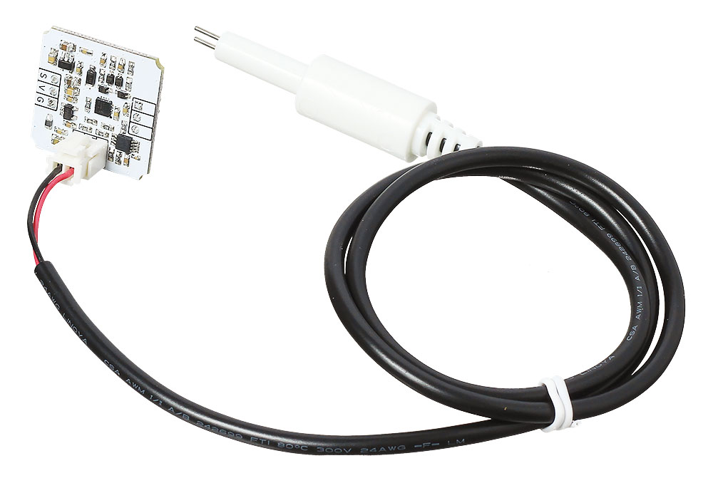
В состав TDS-датчика входит измерительный щуп и плата управления. 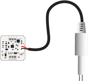 Щуп сенсора выполнен в пластиковом герметичном цилиндре с двумя электродами на конце. При погружении в измеряемый раствор или воду между электродами возникает сопротивление, которое фиксирует и обрабатывает плата управления. А теперь немного подробнее.
Плата управления генерирует с помощью микросхемы LMC555 переменное напряжение, которое поступает на один из электродов щупа. При погружении в жидкость, между электродами возникает сопротивления, которое пропорционально электропроводности раствора. Далее сигнал усиливается и выпрямляется с помощью операционных усилителей на чипе TSX564. На выходе сигнал проходит фильтрацию и поступает на выходной сигнал платы.
TDS-метр измеряет минирелизацию воды, но не определяет её чистоту и безопасность, так как:
Пример работы для Arduino и XOD
В качестве мозга для считывания показаний с датчика рассмотрим платформу из серии Arduino, например, Uno.
Nikkilae/PPM-reader
Use Git or checkout with SVN using the web URL.
Work fast with our official CLI. Learn more.
Launching GitHub Desktop
If nothing happens, download GitHub Desktop and try again.
Launching GitHub Desktop
If nothing happens, download GitHub Desktop and try again.
Launching Xcode
If nothing happens, download Xcode and try again.
Launching Visual Studio Code
Your codespace will open once ready.
There was a problem preparing your codespace, please try again.
Latest commit
Git stats
Files
Failed to load latest commit information.
README.md
PPM Reader for Arduino
PPM Reader is an interrupt based pulse-position modulation (PPM) signal reading library for Arduino. Its purpose is to provide an easy to use, non-blocking solution for reading PPM signals from an RC receiver that is able to output channel data as PPM.
Using interrupts (instead of pulseIn or some equivalent) to detect pulses means that reading the signal can be done in a non-blocking way. This means that using PPM Reader doesn’t significantly slow down your program’s code and you can do any other timing sensitive processes in your program meanwhile reading the incoming PPM signals.
The library uses zeitgeist87’s InterruptHandler library for object-oriented interrupt handling. A copy of a compatible version of the library is included in this repository.
Download the contents of this repository on your computer. Move the downloaded PPMReader and InterruptHandler directories in your Arduino library directory.
Arduino setup and code
Connect your RC receiver’s PPM pin to your Arduino board’s digital pin. Make sure that you use a pin that supports interrupts. You can find information on that from the Arduino language reference.
- Include the library PPMReader.h to your program. If you’re using an older version of Arduino, you may also need to include InterruptHandler.h in your main program.
- Initialize a PPMReader object with its constructor PPMReader(interruptPin, channelAmount); .
- Read channel values from the PPMReader object’s public methods
- Use latestValidChannelValue(channel, defaultValue) to read the latest value for the channel that was considered valid (in between the predetermined minimum and maximum channel values).
- Alternatively use rawChannelValue(channel) to read the latest raw (not necessarily valid) channel value. The contents of the raw channel values may differ depending on your RC setup. For example some RC devices may output «illegal» channel values in the case of signal loss or failure and so you may be able to detect the need for a failsafe procedure.
When referring to channel numbers in the above methods, note that channel numbers start from 1, not 0.
Example Arduino sketch
The PPMReader class should work with default settings for many regular RC receivers that output PPM. The default settings are as follows (all of them represent time in microseconds):
- minChannelValue = 1000 The minimum possible channel value. Should be lesser than maxChannelValue.
- maxChannelValue = 2000 The maximum possible channel value. Should be greater than minChannelValue.
- channelValueMaxError = 10 The maximum error in channel value to either direction for still considering the channel value as valid. This leeway is required because your PPM outputter may have tiny errors and also the Arduino board’s refresh rate only allows a limited resolution for timing functions.
- blankTime = 2100 The time between pulses that will be considered the end to a signal frame. This should be greater than maxChannelValue + channelValueMaxError.
You can modify any of the above settings directly from the PPMReader object. They are public unsigned long variables.
The library has been tested and proven to work on the following setup:
- An Arduino Nano board
- FlySky FS-i6 transmitter with the FS-iA6B receiver
- Up to 6 channels
Please mention any issues, bugs or improvement ideas.
TDS Meter with TDS Sensor and Arduino for water quality monitoring in Realtime
Learn how to measure the TDS value of water by creating an easy realtime TDS monitoring device with Arduino and TDS sensor.
Total dissolved solids (TDS) are measured in milligrams per unit volume of water (mg / l) or also referred to as parts per million (ppm). For drinking water, the maximum concentration level established by the EPA (the United States Environmental Protection Agency) is 500 mg / L. So TDS value is used as a reference in knowing the quality of water for drinking, Aquaponics, hydroponics and where the quality of water matters.
So taking this into consideration we are going to build an IOT TDS monitoring device with the help of Arduino with Gravity Analog TDS sensor which is designed for Arduino with simple plug and play use. As TDS is dependent on temperature we use a waterproof temperature sensor bundled with the TDS sensor probe.
Table of Contents
What is TDS?
TDS (Total dissolved solids), are inorganic compounds found in water, such as salts, heavy metals, and some traces of organic compounds that dissolve in water. Some of these compounds or substances can be essential for life, however, it can be harmful when taking more than the desired amount that the body needs.
How does a tds reader work?
Total dissolved solids at a technical level are measured in a laboratory but if we are interested in measuring it ourselves, the best option is to use an electronic TDS Meter.
The TDS reader works by measuring Electronic conductivity(EC) of water and calculating it and bringing TDS value. This is measured in PPM (Parts Per Million).
Pure H2O water or distilled water does not conduct electricity, so if a TDS reader is immersed in fully distilled water the result will be “0” or a very low number in the event that there are trace minerals in the Water. It is the charge of electrons that make up the minerals that conducts electricity. In short, a water with more minerals conducts more electricity than a water without minerals.
Making of Arduino TDS Meter
Product Requirements:
- Arduino UNO R3
- Gravity analog TDS sensor
- DS18B20 One-Wire Waterproof Temperature Sensor
- JHD162A 16X2 LCD Display ( to dislay the data on mini LCD screen)
- 10k Potentiometer
- 4.7k Resistor
- ESP8266 (ESP-01 or any compatible) (If you need the data over network on blynk).
Software Requirements:
- Arduino IDE
- GravityTDS.h Library
- OneWire.h
- DallasTemperature.h
- ESP8266WiFi
New Product specs:
Gravity Analog TDS sensor:
This sensor is specially designed to be compatible with arduino for measuring water for drinking, aquaponics and more. it operates between input voltages 3.3v to 5v. So it can be uses with multiple compatible MCU’s available, like Arduino, ESP32, Nodemcu, and more. It outputs an analog voltage from 0 to 2.3v.
As the DC signal can add polarization errors to the value and corrode the probe pins used, this sensor uses an AC signal because of no polarity to get better accuracy and for long term usage of the waterproof TDS Probe. The probe has 2 metallic pins through which the electrical conductivity is calculated.
Technical Specs:
- Input DC – 3.3 to 5v
- Output AC – 0 to 2.3v
- Current – 3 to 6 mA
- TDS Measurement Range: 0
1000ppm
Note or warnings:
This electrode probe should be placed in the middle of water placing it near the edges gives wrong values, this probe doesn’t work at temperatures above 55 degree Celsius.
Here we are going to make this project in 3 methods:
- Interfacing with only Arduino and 2 Sensors to watch the readings in Serial monitor.
- Interfacing with Arduino and 2 sensors with LCD display to watch the readings on 16×2 LCD Display.
- Interfacing wirh Arduino and 2 sensors with ESP8266 to watch the readings over wifi with blynk on mobile.
Method1: Results on Serial Monitor
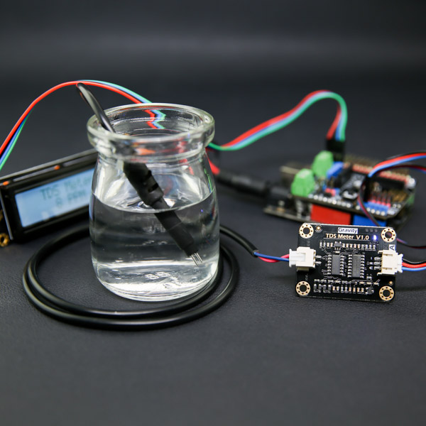
In this method we will interface an Arduino Uno R3 with Gravity TDS sensor and Temperature sensor and monitor the TDS and temperature values on Serial monitor of PC or laptop.
Circuit Diagram:
Circuit diagram with readings only in serial monitor
This is a very simple circuit among the other two just connect the electrode probe with the sensor chip on one side where the other side has 3 pins where one goes to 5v power, second goes to GND, and third goes to Analog pin on arduino A1. And we connect the temperature sensor to digital pin D7 with the help of a 4.7k ohm resistor.
Working:
Upload the below code and connect the components as shown above. then put the TDS and Temperature senors inside the water glass whose TDS value is to be checked. Then open the serial monitor, and you can see the TDS and temperature values. If you don’t want to use temperature sensor you can add the standard temperature value inside code. So, the TDS value is calculated according to the given temperature.
Gravity__Analog_TDS_Sensor___Meter_For_Arduino_SKU__SEN0244-DFRobot
Introduction
TDS (Total Dissolved Solids) indicates how many milligrams of soluble solids are dissolved in one liter of water. In general, the higher the TDS value, the more soluble solids are dissolved in water, and the less clean the water is. Therefore, the TDS value can be used as one reference point for reflecting the cleanliness of water.
A TDS pen is a widely used peice of equipment to measure TDS value. The price is affordable, and it is easy to use, however commonly it is not able to transmit data to a control system for online monitoring of water quality. In general professional instruments have high accuracy and can send data to the control system, but the price is expensive for the ordinary person. To this end, we have launched an analog TDS sensor kit which is compatible with Arduino, plug and play, and is easy to use. Matching with Arduino controller, you can build a TDS detector easily to measure the TDS value of liquid without needing to purchase expensive equipment.
This product supports 3.3
5.5V wide voltage input, and 0
2.3V analog voltage output, which makes it compatible with 5V or 3.3V control systems or boards. The excitation source is AC signal, which can effectively prevent the probe from polarization and prolong the life of the probe, meanwhile can help increase the stability of the output signal. The TDS probe is waterproof, it can be immersed in water for long time measurement.
This product can be used in water quality application, such as domestic water analysis and hydroponics. With this product, you can easily DIY a TDS detector to reflect the cleanliness of water to protect your health!
 | Attention: 1.The probe can not be used in water above 55 degrees centigrade. 2.The probe can not be left too close to the edge of the container, otherwise it will affect the reading. 3.The head and the cable of the probe are waterproof, but the connector and the signal transmitter board are not waterproof. Please be careful. |
|---|
Specification
- Signal Transmitter Board
- Input Voltage: 3.3
5.5V
Output Voltage: 02.3V
Working Current: 36mA
TDS Measurement Range: 01000ppm
- TDS Measurement Accuracy: ± 10% F.S. (25 ℃)
- Module Size: 42 * 32mm
- Module Interface: PH2.0-3P
- Electrode Interface: XH2.54-2P
- Number of Needle: 2
- Total Length: 83cm
- Connection Interface: XH2.54-2P
- Colour: Black
- Other: Waterproof Probe
Board Overview
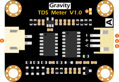
| Num | Label | Description |
|---|---|---|
| 1 | — | Power GND(0V) |
| 2 | + | Power VCC(3.3 5.5V) |
| 3 | A | Analog Signal Output(0 2.3V) |
| 4 | TDS | TDS Probe Connector |
| 5 | LED | Power Indicator |
Basic Tutorial
This tutorial will show you how to measure the TDS value of the water. Please read this tutorial carefully, and pay attention to the steps and details.
| The probe can not to be used in water above 55 degrees centigrade. The probe can not be too close to the edge of the container, otherwise it will affect the reading. The head and the cable of the probe are waterproof, but the connector and the signal transmitter board are not waterproof.Please pay attention to use. |
|---|
Requirements
Hardware
- DFRduino UNO R3 (or similar) x 1
- Analog TDS Sensor / Meter Module x 1
- TDS Probe x1
- Jumper Wires x3
- tested liquid x1
Software
Connection Diagram
Sample Code
Expected Results
After uploading the sample code,open the serial monitor of the Arduino IDE. Then insert the TDS probe into the water, and gently stir it. Then wait for the reading to be stable, and you will get the TDS value of the water. 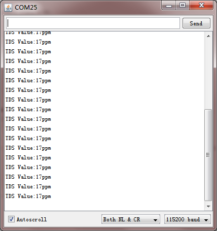
Advanced Tutorial
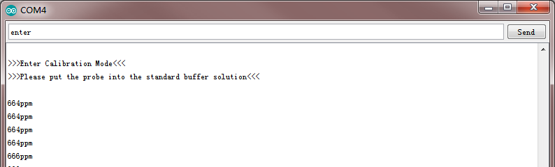
Through the basic tutorial the TDS value of the liquid can be easily measured. However, due to the individual differences of different TDS probe, differences of the main control board, and no onboard temperature compensation, the measured value can have some errors.Therefore, to obtain a more accurate TDS value, calibration is required before measurement. In addition, it is recommended to connect a temperature sensor for temperature compensation to improve accuracy. Normally, the TDS value is half of the electrical conductivity value, that is: TDS = EC / 2. The wiring diagram is same as the basic tutorial. During the calibration, a liquid solution of known electrical conductivity or TDS value is needed, such as 1413us/cm standard buffer slution. If converted to a TDS value, it is about 707 ppm. The TDS value can also be measured using a TDS pen if you do not have a standard buffer solution. The following will demonstrate how to calibrate.
Sample Code
Calibration Step
Uploaded the sample code to your controller board, then open the serial monitor.
Clean the TDS probe, then dry it with absorbent paper. Insert the probe into the buffer solution of known electrical conductivity or TDS value, then stir gently and wait for stable readings. If you do not have the standard buffer solution, a TDS pen can also measure the TDS value of the liquid solution.
Input command «enter» to enter the calibration mode.
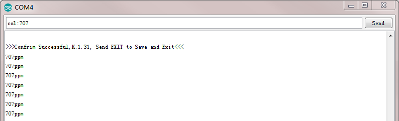
- Input command «cal:tds value» to calibrate the sensor.In this example, I use the 707ppm buffer solution, so I need to input command «cal:707».
- Input command «exit» to save and exit.
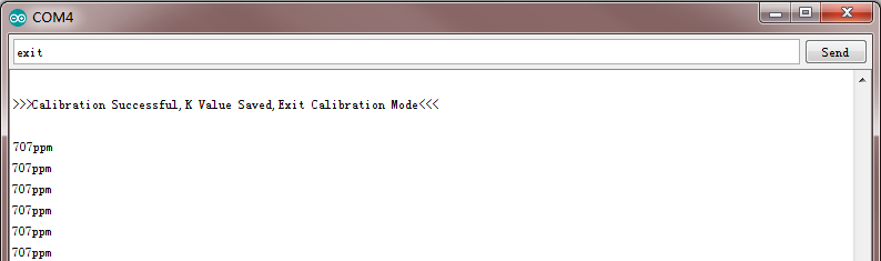
- After the calibration, you can use the TDS sensor in your application now.
| Q1. Does this sensor have a temperature sensor? How to make the temperature compensation? |
|---|
| A1. This TDS probe has no temperature sensor, but the temperature compensation algorithm is reserved in the sample code. The temperature variable in the sample code will default to 25 °C without a temperature sensor. You can add a waterproof temperature sensor to read the temperature,then update the temperature variable, to make automatic temperature compensation. |
| If you have any questions about using this product, please check the FAQ list for that product for a corresponding solution. And for any questions, advice or cool ideas to share, please visit the DFRobot Forum. |
|---|
More Documents
 Get Gravity: Analog TDS Sensor/Meter for Arduino from DFRobot Store or DFRobot Distributor.