Lesson 1: Turning on an LED
Table of Contents
For our first learning activity, we are going to use Arduino to turn on an LED. We’re not going to write any code. Instead, our goal is to build some initial familiarity with Arduino hardware and connecting components to Arduino pins before we introduce programming, which we do in the next lesson.
 Figure The movement of current in the circuit is illustrated by the animated yellow circles. This visualization is a coarse abstraction designed to emphasize the direction of current flow. A more accurate visualization would show that electrons are already distributed throughout a wire before a voltage is applied. See our Introduction to Electronics series, specifically the lesson on Voltage, Current, and Resistance.
Materials
For this lesson, you will need the following materials. Please build with us to advance your understanding and skillset—the best way to learn is by doing!. For those students enrolled in our courses, please document your creation journeys in your prototyping journals and attempt to answer and reflection on posed questions.
| Arduino | LED | Resistor |
|---|---|---|
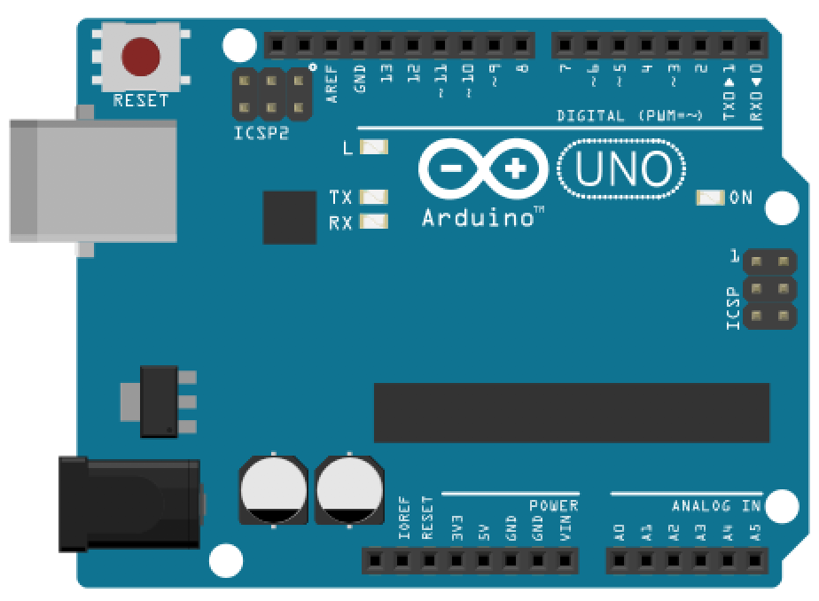 |  |  |
| Arduino Uno, Leonardo, or similar | Red LED | 220Ω Resistor |
We’ll be using the Arduino Leonardo for these introductory microcontroller lessons but any 5V board will work, including the Arduino Uno, Adafruit’s METRO 328, Sparkfun’s RedBoard, etc. Each of these boards have the same pin layout and general specifications.
Hook up LED to Arduino’s 5V supply pin
Step 1: Wrap resistor around LED leg
Grab a 220Ω resistor (or any resistor 220Ω or greater) and twist one leg around an LED leg. If you want to follow my example exactly, connect the resistor to the LED’s anode (long leg) but either leg will work. (Remember, a current limiting resistor can go on either side of an LED, see our LED lesson).
To wire wrap your components, simply twist the legs together like this:
Video. An example of wire wrapping a 220Ohm resistor leg (or lead) directly around the anode of an LED
Step 2: Connect components to Arduino
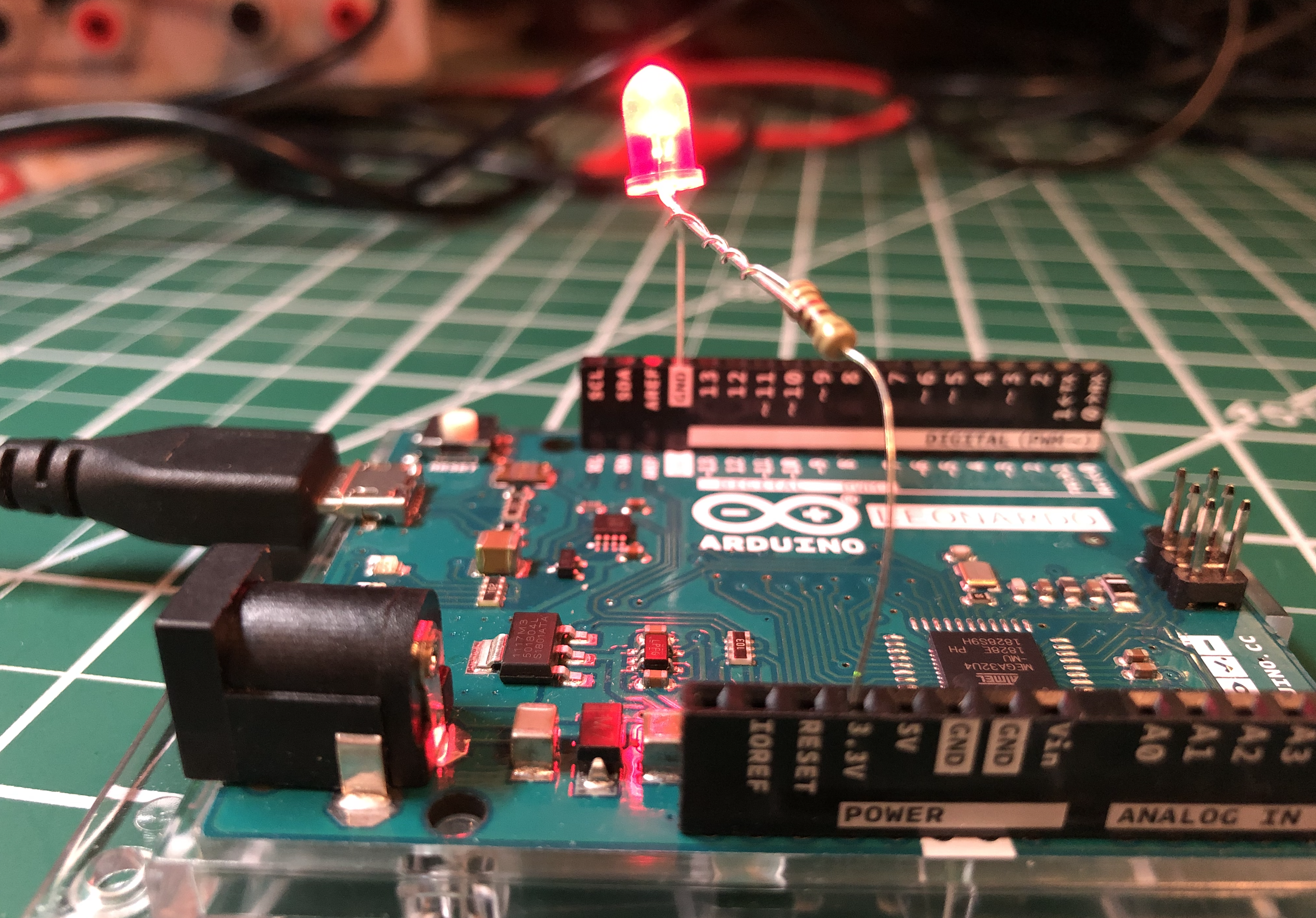
Insert the LED + resistor into the Arduino: the LED’s cathode (short leg) to GND and the LED’s anode (long leg) + resistor to the Arduino’s voltage supply, which you can access via the 5V pin.
Step 3: Connect your Arduino to power
Now connect your Arduino to power and the LED should light up. You did it!
Here’s a photo of the version I made. I found it easier to stretch the wiring across the Arduino from the 5V port to the GND on the opposite side.
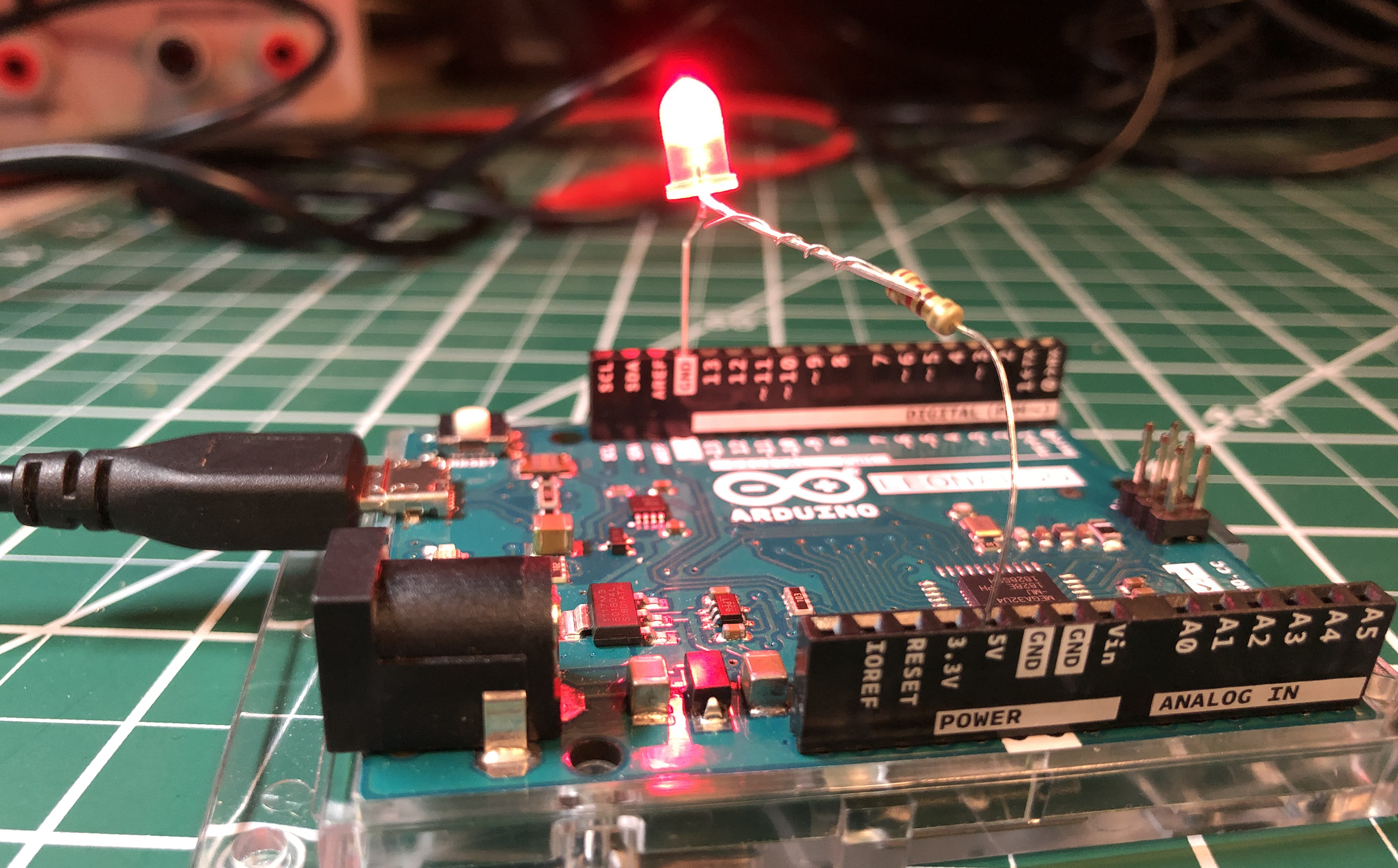
For power, you can use a USB cable (which supplies 5V) or a 9V battery (which supplies 9V). Either way, the Arduino supplies 5V through the 5V pin. How? Using a voltage regulator. See “More Info” below.
| USB Power | 9V Power |
|---|---|
 |  |
| With USB power, the 5V pin supplies 5V | Using the Arduino’s barrel jack, we can connect an external power supply like a 7-12V wall adapter or a 9V battery. The Arduino’s internal voltage regulator reduces these higher voltages to output a clean 5V |
Let’s analyze our circuit
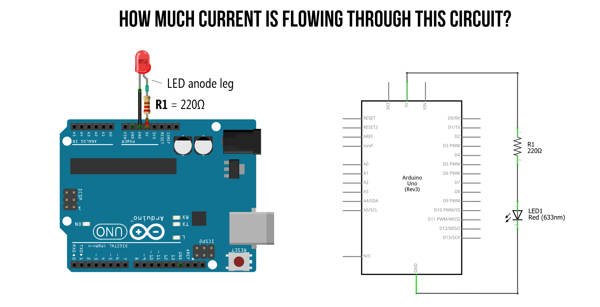
Just as we did in our LED lesson, let’s analyze how much current is flowing through this simple LED-based circuit. To do this, we first need to determine the voltage drop across the resistor \(V_R\) and then use Ohm’s Law to figure out the current (\(I = \frac
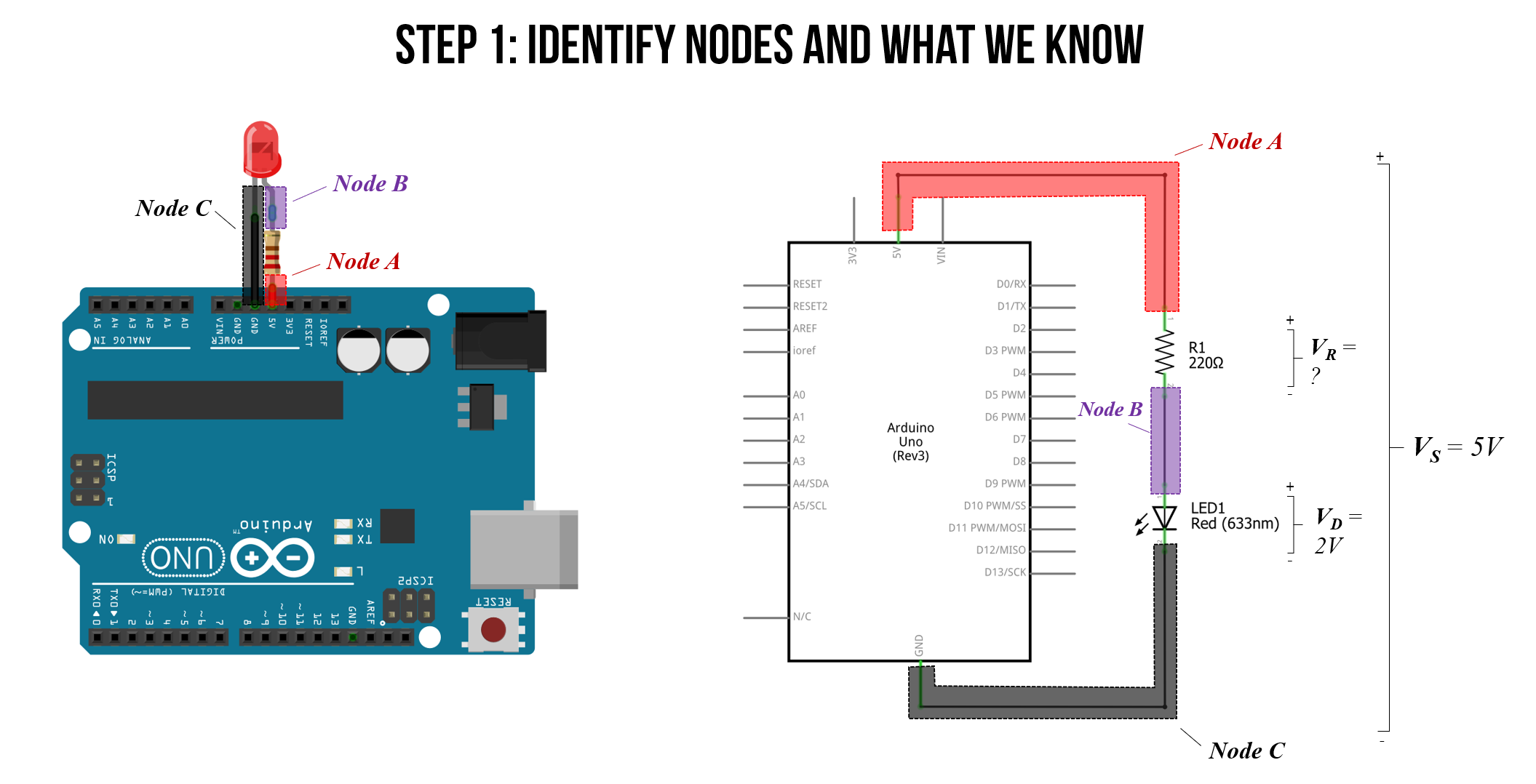
Step 1: Identify nodes and what we know
We always start by identifying nodes and what we know. We know that as long as \(V_f\) is satisfied, that there will be a voltage drop \(V_R\) across our resistor and a voltage drop \(V_D\) across our LED.
Due to Kirchhoff’s Circuit Laws, we know that the total voltage drop across both the resistor and LED (\(V_R + V_D\)) must equal our supply voltage \(V_S=5V\). From our LED lesson, we know that our circuit is off until the “on” or “forward” voltage of our LED is met, which for a red LED is
2V. Thus, we can set \(V_D=2V\) and solve for \(V_R\).
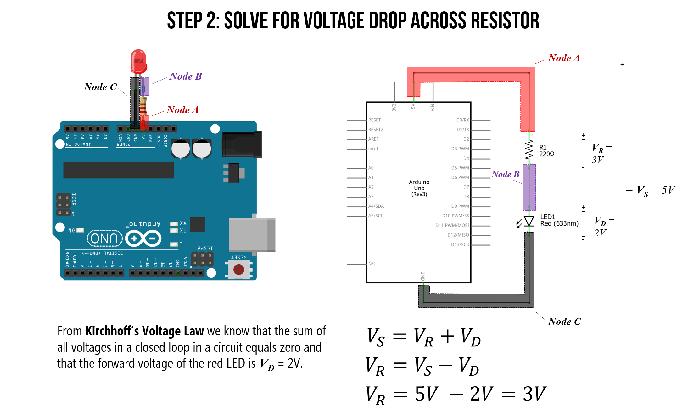
Step 2: Solve for voltage drop across the resistor
Solving for \(V_R\):
\[V_S = V_R + V_D \\ V_R = V_S — V_D \\ V_R = 5V — 2V = 3V\]
Step 3: Solve for current
From Ohm’s Law, we know that the total current in our circuit is equal to the voltage drop across our resistor \(V_R\) divided by the resistance value \(R\). That is, \(I = \frac
\[I = \frac
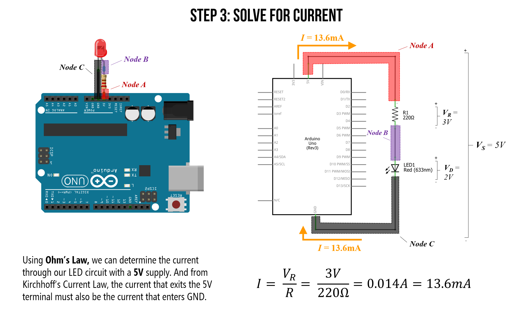
So, with the 5V supply pin, our circuit is drawing 13.6mA of current. Is this a lot or a little? Let’s put this in context below.
Maximum current draw
The Arduino has a variety of pin types, each with their own maximum current ratings.
I/O Pins: The maximum current draw of any single I/O pin—which we haven’t used yet but we will in the next lesson—is 40 mA (a safer, continuous range is
20mA). The total current across all I/O pins together is 200mA. If we exceed these values, we could damage our Arduino board or the underlying microcontroller (the ATmega328 for the Uno or the ATmega32u4 for the Leonardo)
Power supply pins: The 5V output pin can supply
400-500mA when powered by USB and
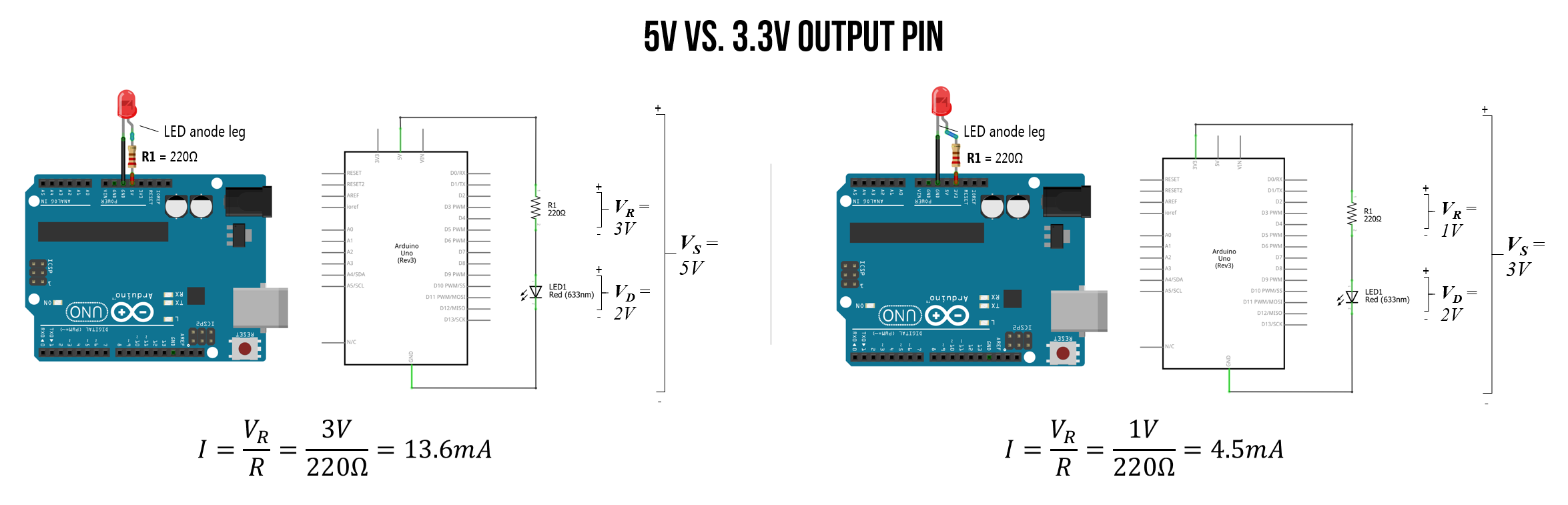
900-1000mA when using an external power adapter. The 3.3V output pin can supply
150mA; however, if you have both 3.3V and 5V output pins connected, any current drawn from the 3.3V pin will be counted against 5V’s total current.
The only protection fuse is a resettable polyfuse on the USB port, which limits current to 500mA on the 5V output pin (but only when powered by USB).
There are a variety of discussions about the Arduino Uno and Leonardo’s maximum current draw online. The best resource I’ve found are these StackExchange posts, which also link to datasheets (post1, post2).
Maximum number of LEDs in series
An interesting question to ponder then is: with the Arduino powered via USB (max 500mA current), how many red LEDs could you hook up in series to the 5V supply pin? How about in parallel? What is the limiting factor for each?
Well, for a simple series configuration, the total number of series LEDs is limited to the voltage supply, which is 5V. With a 200Ω resistor and a red LED with a “forward” voltage of \(V_f=2V\), we are limited to a maximum of two LEDS: \(2 * 2V = 4V\). However, in practice, I was able to get three LEDs in series (because the LED begins to turn on a bit around
1.7-1.8V) though they were quite dim. See the table and image below for my measurements.
| Resistor | Num Red LEDs in Series | Voltage Drop Across Each LED | Voltage Drop Across Resistor | Current | ||||||||||||||||||||||||||||||||||||||||||||||||||||||||
|---|---|---|---|---|---|---|---|---|---|---|---|---|---|---|---|---|---|---|---|---|---|---|---|---|---|---|---|---|---|---|---|---|---|---|---|---|---|---|---|---|---|---|---|---|---|---|---|---|---|---|---|---|---|---|---|---|---|---|---|---|
| 200Ω | 1 | 2.02V | 2.95 | 14.9mA | ||||||||||||||||||||||||||||||||||||||||||||||||||||||||
| 200Ω | 2 | 1.92V | 1.21V | 6.1mA | ||||||||||||||||||||||||||||||||||||||||||||||||||||||||
| 200Ω | 3 | 1.71V | 0.021V | 0.1mA | ||||||||||||||||||||||||||||||||||||||||||||||||||||||||
| 200Ω | 4 | 1.01V |
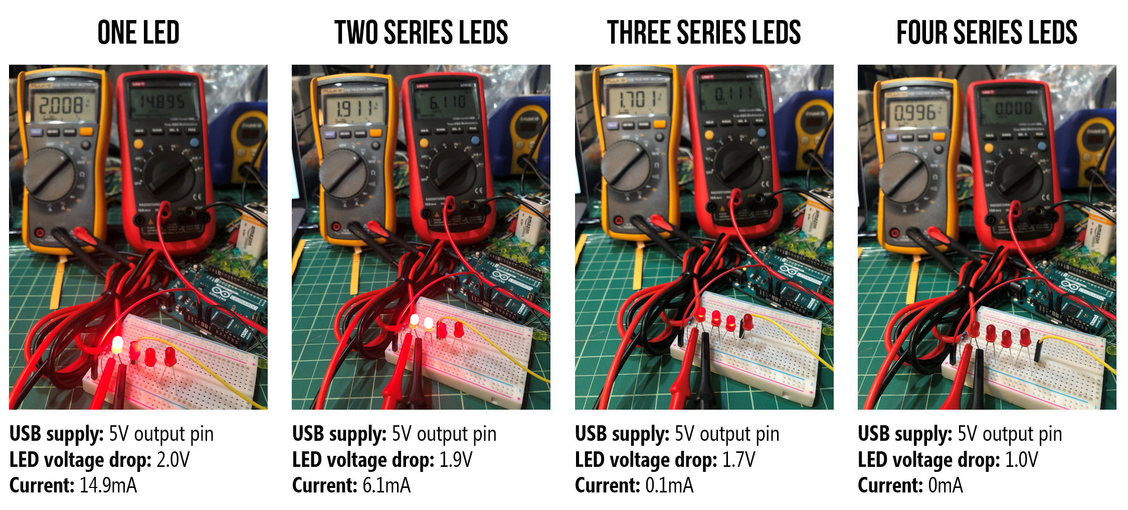 Figure. Measuring the individual LED voltage drop and current through the circuit using two multimeters: the yellow multimeter configured as a voltmeter to measure the voltage drop \(V_D\) over the first LED in the circuit and the red multimeter configured as a ammeter to measure the current \(I\) through the circuit.
 Figure. 34 LEDs in parallel draws 514.1mA of current, which exceeds the maximum amount of the 5V output pin on the Arduino (when powered by USB). Here’s the CircuitJS link.
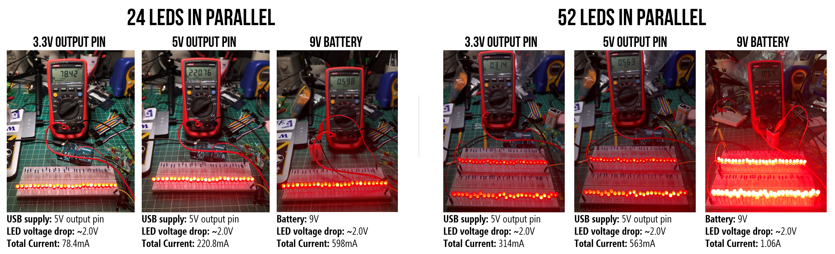 Figure. I “stress tested” the 5V output pin using the USB for power. Do not attempt! Despite exceeding the rated maximums, I failed to trigger the Arduino’s internal fuse on the 5V or 3.3V supplies. Note, the I/O pins do not have such protect so you could damage your board if you overdraw current.
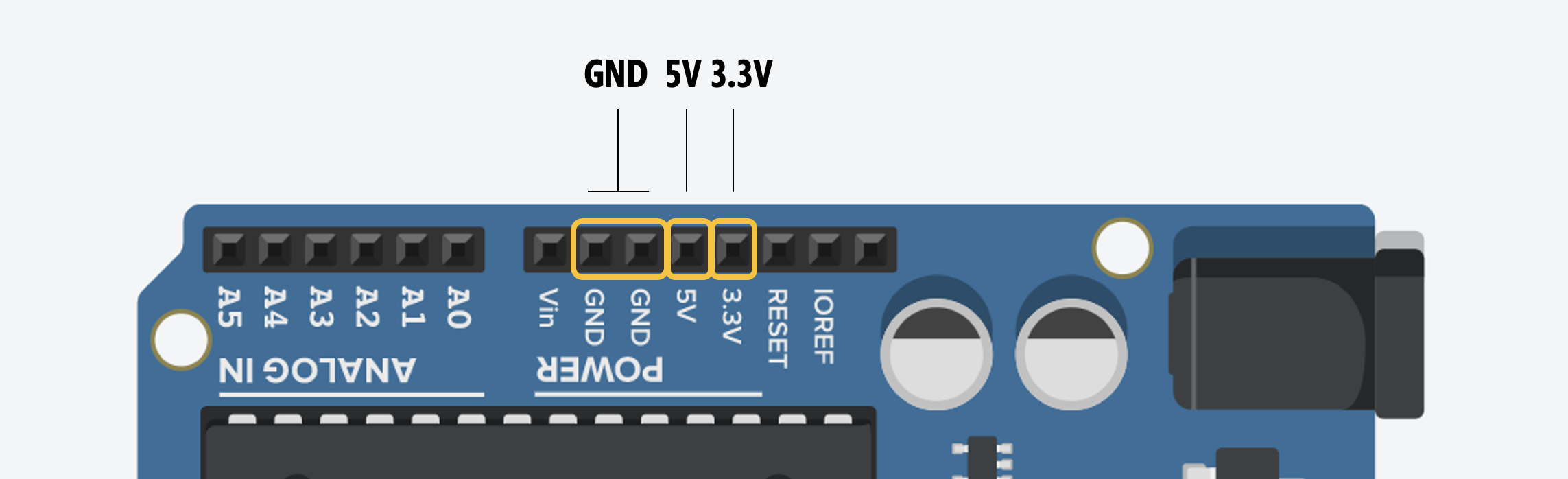
| Resistor | Resistor Image | Vs | Resulting Current |
|---|---|---|---|
| 220Ω | 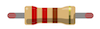 | 5V | \(I = \frac<3v><220Ω>= 13.6mA\) |
| 680Ω |  | 5V | \(I = \frac<3v><680Ω>= 4.4mA\) |
| 1kΩ | 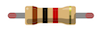 | 5V | \(I = \frac<3v><1,000Ω>= 3mA\) |
| 2.2kΩ |  | 5V | \(I = \frac<3v><2,200Ω>= 1.4mA\) |
| 10kΩ | 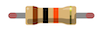 | 5V | \(I = \frac<3v><10,000Ω>= 0.3mA\) |
We can verify these theoretical predictions using a multimeter to measure (\(V_s\)), the actual resistor values, and the current \(I\). We conducted these measurements using a Fluke 115 True RMS Multimeter.
A few important notes:
- Each electronic component that we use from the LED to the resistors to the supply voltage (\(V_s\)) are going to differ slightly from ideal. Our carbon film resistors, for example, have a tolerance of 5% (indicated by the gold band), and I measured our supply voltage on the Arduino Uno to be (\(V_s\)=4.902V) rather than 5V.
- The Fluke 115 provides three digits of precision. So, the multimeter reads 0.013A, 0.004A, etc. Thus, it’s not possible to compare our theoretical predictions to the 4th digit of precision (which impacts our low current—milliamp—comparisons).
Again, we assume a \(V_f=2V\) for our red LED (we could also measure this directly in each circuit):
| Resistor | Resistor Image | Measured Resistance | Measured Vs | Measured Current | Ohm’s Law |
|---|---|---|---|---|---|
| 220Ω | | 218.8Ω | 4.902V | 13mA | \(I = \frac<2.902V><218.8Ω>= 13.3mA\) |
| 680Ω | | 680Ω | 4.902V | 4mA | \(I = \frac<2.902V><680Ω>= 4.3mA\) |
| 1kΩ | | 994Ω | 4.902V | 3mA | \(I = \frac<2.902V><994Ω>= 2.9mA\) |
| 2.2kΩ | | 2.204kΩ | 4.902V | 1mA | \(I = \frac<2.902V><2,204Ω>= 1.3mA\) |
| 10kΩ | | 9.92kΩ | 4.902V |
In the next lesson, we will learn how to programmatically control the output voltage of a digital I/O pin to switch between LOW (0V) or HIGH (5V) using digitalWrite(int pin, int value) .
All content is open source and produced by the Makeability Lab and Professor Jon E. Froehlich. Found an error? File a GitHub Issue.
Adblockdetector