How to Use OLED Display with Arduino | Arduino OLED Tutorial
In first part, we will show DHT22 sensor’s data on the OLED. In the second part, we will display iPhone, Samsung and LG’s logos on OLED.
In this tutorial, you are going to learn about Arduino OLED interfacing. In the first part, we will show temperature and humidity sensor’s data on the OLED and in the second part, we will display the iPhone, Samsung and LG’s logo on the OLED.
Before connecting it with Arduino, let’s get into details of What OLED is and How does it Works.
For Custom Projects, hire me at https://www.freelancer.com/u/Muhammadaqibdutt
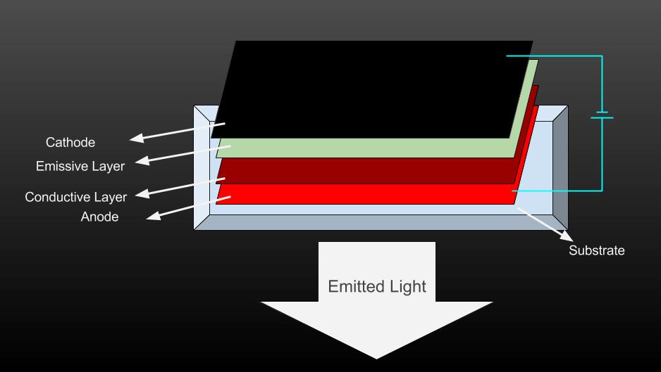
OLED stands for Organic Light Emitting Diode. The OLED displays are very small and have high resolution. These displays have no back light and they makes their own light. That’s why these are very low power devices.
When the voltage is applied to the OLED. The current flows from the cathode to anode through the organic layers of the OLED. The cathode gives the electrons to the emissive layer of organic molecules and the anode removes electrons from the conductive layer of organic molecules.
At the boundary between the conductive and emissive layer, electron holes are created. These holes are filled by the electrons and the OLED emits light. The color of the OLED depends upon the organic molecules used.
OLED and Arduino
The OLED that we are going to use has individual 128X64 white OLED pixels. It is 0.96’’ (25mm X 14mm) in size. The OLED’s of other sizes are also available. The OLED used in this tutorial is monochrome (Only one color) but you can also get the OLED’s having several colors.
This OLED uses the SPI communication to communicate with Arduino. The SPI communication is faster than the I2C communication so this will make our display faster.
The OLED runs on 3.3V so do not connect it to 5V of Arduino. It may work but the lifetime of the OLED will decrease.
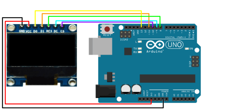
Make the connections for the OLED and the DHT22 with Arduino as show in below circuit diagram

If you want to read more about DHT22 interfacing with Arduino, then follow this Tutorial| Temperature and Humidity Sensor DHT22 interfacing with Arduino
Download the library from the below link
For the OLED, we have used the U8glib library. Let’s see how the library is working.
The data is printed on the OLED in the form of picture loops. The firstPage() shows the start of the picture loop. Next to it, we need to create the “do while” loop. Anything we want to show on the OLED should be written inside “do while” loop. The “do while” loop will keep on running until the nextpage() returns a ‘1’.
The u8g.setFont(u8g_font_helvB10) command will set the font. This library has different font sizes and design which you can find from the below link.
The u8g.drawStr(30, 10, “Welcome “) command will print the “welcome” at the X, Y position. The value ‘30’ is for the horizontal position(X) and the value ‘10’ is for the vertical position(Y). The other draw commands are also working like that.
The u8g.setPrintPos(75, 15) command used in the code will set the pointer to X (75), Y (15) position. Then you can print the sensor output there by using the u8g.print() command.
How to draw Bitmap pictures on OLED
Now let’s draw the bitmap pictures on the OLED. We will draw the IPhone, Samsung and LG logos on the OLED. The circuit diagram for this example is shown below.
The maximum size of picture to be drawn on the OLED should be 128X64 pixels and the picture should be black and white because our OLED is monochrome which means that it has only one color. If you have multiple color OLED, then you can display the color pictures.
I downloaded the black and white logos and resized them in the paint tool. Paint has the resize option in the Home menu as highlighted with yellow color in below image. If resize option doesn’t do the work then you can also drag the drawing area from the small rectangles as circled in below image.
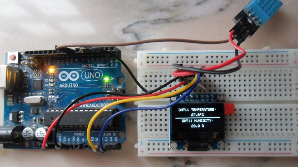
DHT22 & 0.96 OLED Display

Introduction: DHT22 & 0.96 OLED Display
I know there are lots of Instructables showing how to use a DHT22 and a 0.96 OLED display but I thought I’d show how I made mine!
Step 1: Required Components
For this Instructable I’m using the following easily available parts:
Arduino Uno or compatible
0.96 OLED display
Breadboard and jumper wires.
Step 2: Connecting It All Together
Connect the parts as follows:
DHT22 pin1 to Arduino 5v
DHT22 pin2 to Arduino pin2
DHT22 pin3 to Arduino Ground (GND)
OLED GND to Arduino Ground (GND)
OLED VDD to Arduino 5v
OLED SCK to Arduino D5
OLED SDA to Arduino D4
Step 3: The Code
This is the code I used to get the readings from the DHT22 and display them on the 0.96 OLED.
I used the U8G2 display library as I wanted a bit more control over the text size and fonts used.
Attachments
2 People Made This Project!


Did you make this project? Share it with us!
Recommendations


Teach With Tinkercad Contest

Metal Contest

Microcontroller Contest

6 Comments

I made it! Thanks for sharing the code.


me aparece error en la pantalla
t=nan *c
h=nan % .
como puedo corregirlo

OLED D4 = A4
OLED D5 = A5
then it works great

Seriously, THANK you for sharing. This Instructable really helped me understand some of the coding aspects i wasn’t getting through my thick skull.
One thing i am still having trouble figuring out though, is how to convert the Temp to Fahrenheit.
Any tips or clues would be really appreciated. Thanks again.
Arduino with SSD1306 OLED and DHT11/DHT22 sensor
This post shows how to build a temperature and relative humidity measurements station using Arduino and DHT11/DHT22 sensor where the measured values of the temperature and the humidity are displayed on 128×64 OLED screen with SSD1306 driver. (OLED: Organic Light-Emitting Diode)
The SSD1306 OLED used in this post projects is configured to work in I2C mode, some SSD1306 OLED boards may require a small hardware modifications (to select between SPI mode or I2C mode) such as soldering, placing jumpers …. To see how to connect the SSD1306 OLED with Arduino read the post below:
Interfacing Arduino with SSD1306 OLED display
I used Adafruit SSD1306 OLED library to simplify the connection of the Arduino with the screen and Adafruit DHT library for the connection between the Arduino and the DHT11/DHT22 sensors. Both libraries can be downloaded through Arduino IDE Library Manager of manually from the links below (after downloading, unzip the folder and place it in Arduino libraries folder, for example C:\Program Files\Arduino\libraries)
Adafruit SSD1306 OLED library — direct link
Adafruit DHT library — direct link
We also need Adafruit graphics library:
Adafruit GFX library — direct link
- Arduino board
- SSD1306 OLED screen (128×64 Pixel)
- DHT11/DHT22 temperature and humidity sensor
- 4.7k ohm resistor
- Breadboard
- Jumper wires
Interfacing Arduino with SSD1306 OLED and DHT11 sensor:
Circuit connections are shown below where:
SSD1306 OLED GND goes to Arduino GND (ground)
SSD1306 OLED VDD to Arduino 5V
SSD1306 OLED SDA pin (serial data) to pin A4 (Arduino UNO I2C SDA pin)
SSD1306 OLED SCK pin (serial clock) to pin A5 (Arduino UNO I2C SCL pin)
SSD1306 OLED RES pin (reset) to Arduino pin 4
DHT11 data pin to Arduino pin 8
DHT11 DHT22 with ESP32 – Display Readings on OLED
In this user guide, we will learn to interface the DHT11 and DHT22 with ESP32 which is used for humidity, and temperature using Arduino IDE. Firstly, we will learn about DHT11/DHT22 such as its introduction, pinout diagram, and interfacing diagram with ESP32. Secondly, we will see how to install the DHT sensors library in Arduino IDE. Lastly, we see two examples to display temperature and humidity values on a serial monitor and also on the SSD1306 OLED display.
We have a similar guide for DHT11 and DHT22 with ESP32 using MicroPython:
Table of Contents
DHT11/DHT22 Introduction
The DHT11/DHT22 is a sensor which measures relative humidity and temperature sensor. It provides a calibrated digital output with a 1-wire protocol. Both sensors are inexpensive. They are quite similar to each other with some differences in specifications.
DHT22 is almost similar to the DHT11 but the former measures temperature and humidity with higher accuracy and supports a wider range.
DHT11 vs DHT22
The following table lists the comparison of both DHT sensors.
| DHT22 | DHT11 | |
|---|---|---|
| Temperature | -40 to 80 ºC +/- 0.5ºC | 0 to 50 ºC +/-2 ºC |
| Humidity | 0 to 100% +/-2% | 20 to 90% +/-5% |
| Resolution | Humidity: 0.1%Temperature: 0.1ºC | Humidity: 1%Temperature: 1ºC |
| Operating Voltage | 3- 6 V DC( directly powerable from ESP32/ESP8266) | 3-5.5 V DC( directly powerable from ESP32/ESP8266) |
| Sampling time | 2 seconds | 1 second |
| Current rating | $4 to $10 | $1 to $5 |
| Output data type | float | int |
| Pinout | 4-pin (same as DHT11) | 4-pin (same as DHT22) |
| Price ($) | 5 | 2 |
As you can see from the above comparison table that DHT22 offers a wider temperature range and resolution for temperature and humidity. But it is more expensive than DHT11. However, DHT11 has a better sampling period. Furthermore, the operating voltage range for both sensors is almost and we can directly power these sensors from power pins of ESP32 and ESP8266.
Regardless of the above differences, both DHT sensors have the same working principle and same pinout. We can use the same Arduino sketch to read temperature and humidity readings by selecting the DHT type inside the code.
DHT sensors are pre-calibrated. We can directly connect them with ESP32/ESP8266 to obtain sensor output reading. They are internally composed of a humidity sensing sensor and a thermistor. These two components measure humidity and temperature.
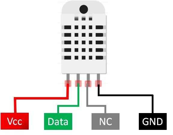
DHT11/DHT22 Pinout
This following figure shows the pinout diagram of DHT sensors. DHT sensor consists of four pins. But on DHT modules only three pins are exposed to the pinout of the module and10k ohm pull-up resistor is internally connected to pin 2.
Pin Description
The following lists the pinout of the DHT sensor and their brief description. Pin number starts from left to right when you hold the sensor from the front end.
| DHT11/DHT22 Pin | ESP32 |
|---|---|
| 1 ( Vcc ) | 3.3V |
| 2 ( Data Out ) | Any GPIO pins of ESP boards along with a 10k ohm pull-up resistor |
| 3 (NC) | Not used |
| 4 ( GND ) | Ground |
- Vcc is the power supply pin. Apply voltage in a range of 3.3 V to 5.0 V to this pin
- Data Out is the digital output pin. It sends out the value of measured temperature and humidity in the form of serial data
- N/C is not connected
- GND: Connect the GND pin
Parts Required
You will need the following components
- ESP32
- DHT11/DHT22
- Bread Board
- 10K ohm resistor
- Jumper wires
DHT11/DHT22 Interfacing with ESP32
Connect the DHT11/DHT22 to ESP32 along with a 10K ohm pull-up resistor. The connection diagrams are shown in the pictures below.
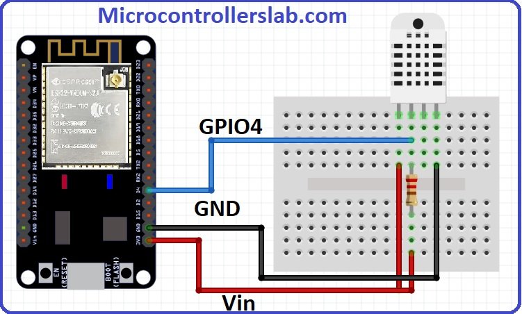 DHT22 Interfacing with ESP32
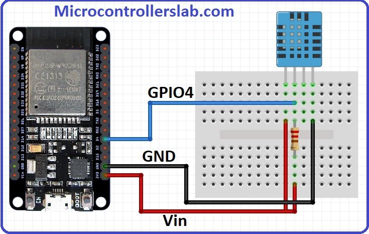
- The first pin for both sensors is a power supply(Vcc) pin. Connect it with the 3.3 volt pin of ESP32.
- Data out is the pin through which we get temperature and humidity samples from the DHT sensor. Connect this pin with GPIO4 of ESP32 and also connect the data pin with a 10k pull-up resistor. But you can also use any digital pin of ESP32.
A Pull-up resistor is used to keep the data pin high for proper communication between the microcontroller and sensor. You can check the datasheet of DHT11 and DHT22 to get more information about it. DHT22 is also known by the name of AM2302.
- Third pin is not used
- Connect the fourth pin (GND) to the ground pin of the ESP32 board
Installing DHT11/DHT22 Library in Arduino IDE
Both DHT11 and DHT22 provide the output of temperature and humidity in the complex digital output format which can not be directly read with GPIO pins without writing any technique which can read these output signals. These sensors provide data through a single wire two-way communication protocol. A single process communication consists of 40 bits. But we do not need to worry about the working of these sensors and on which protocol we can receive this data. We have an Arduino library for DHT sensors which can be easily used to get values of temperature and humidity only by calling two lines of functions. We will see later on how to do it. Now let’s see how to install the DHT library in Arduino. This library is provided by Adafruit. Follow these steps to install the DHT sensor library:
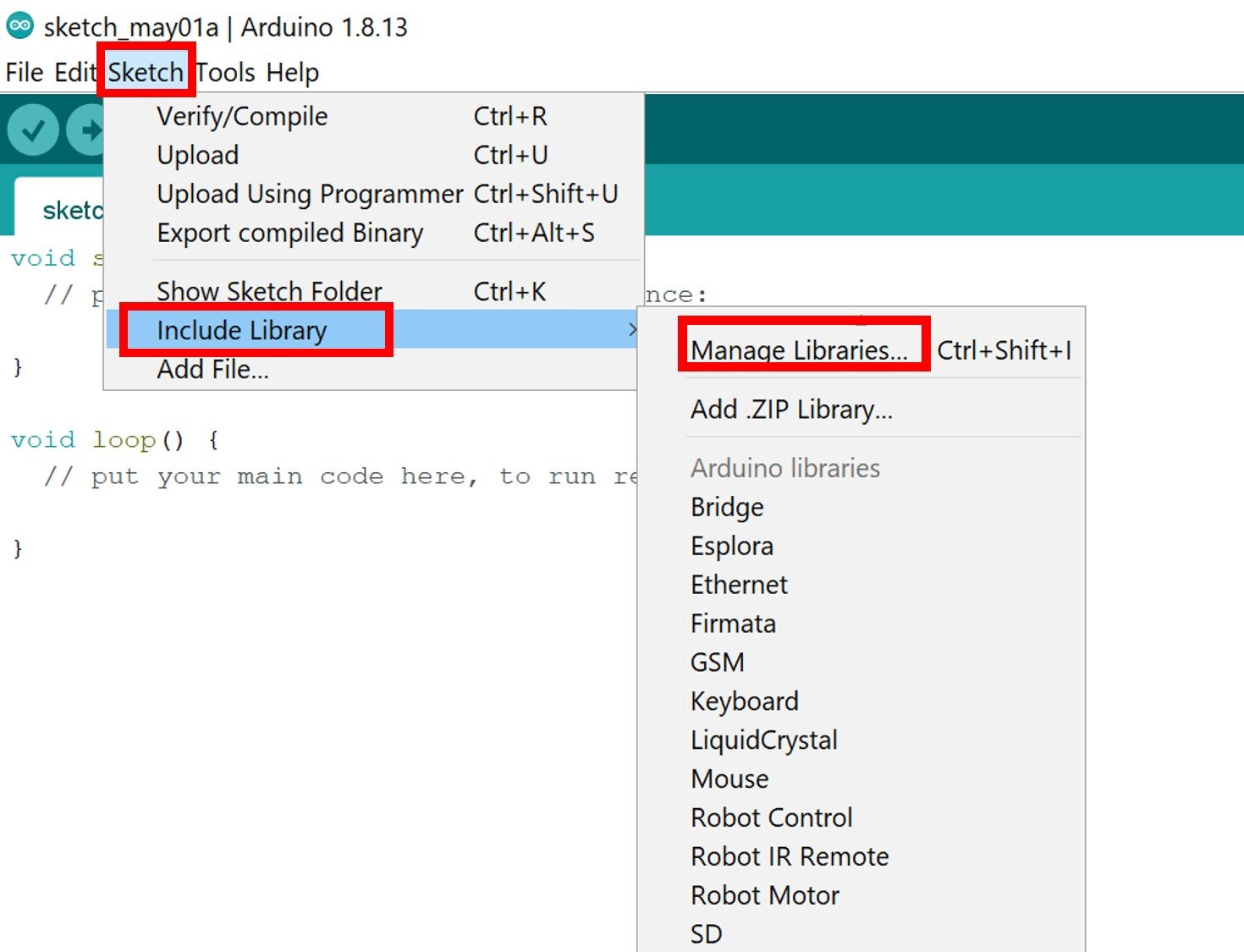
Go to Sketch menu>> include file and click on manage libraries option.

When you click on the manage libraries option, you will get this window. In this window write ‘ DHT sensor ‘ in the search bar and press enter.

You will see many options available for DHT11 and DHT22 libraries. Select Adafruit library and click on the install button. You can select the latest version from the version window.
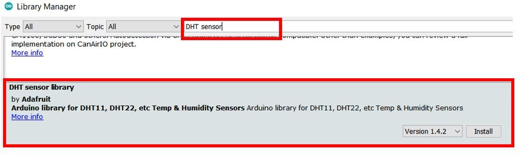
The same library can be used for both DHT11 and DHT22/AM2302 sensors. After that, you will see the message of library correctly installed.
Now click on the close button. This library is now successfully included in the library manager of Arduino IDE. This is a very powerful library. Because we can use the same library for different types of microcontrollers like Arduino and STM32 microcontrollers.
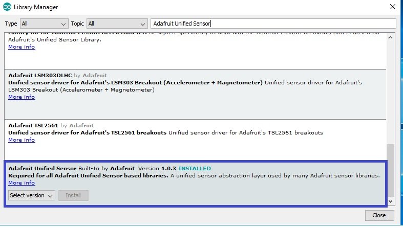
Adafruit also provides libraries for other sensors. So they provided a support package which is used to handle all sensor libraries. We also need to install the Adafruit Unified Sensor library. To install this, paste the Adafruit Unified Sensor search bar and select this option and click on install button.
DHT11/DHTT22 Display Readings on Arduino Serial Monitor
In this section, we will see how to take temperature and humidity readings from DHT11 and DHT22. After that display sensors readings on Arduino serial monitor. The following Arduino sketch serves this purpose. Copy this sketch to Arduino IDE and compile it.

How Code Works?
Include DHT Libraries
Now, we will explain the working of the sketch line by line. At the start of the sketch, we have added two libraries for DHT sensors and wire library. These libraries are necessary to include to use its related functions within the code.
Define DHT22 Object
This is used to define which type of DHT sensor we want to use. You can use this with DHT11, DHT21, and DHT22 sensors. You should uncomment the line according to the sensor you are using. For example, we are using DHT22 in this tutorial, we have uncommented this, and others are remain commented. DHTTYPE variable stores the name of the sensor we are using.
We have defined the name of the GPIO pin of ESP32 with which we will connect the DHT11/DHT22 sensor. We are using GPIO pin number four. Therefore, we should define pin number four.
This line will create the object of DHT according to our defined pin number and DHT type. We have defined both these parameters in the last steps.
These three float type variables will be used to store values of temperature in Celsius, Fahrenheit, and humidity.
Initialize DHT11/DHT22 Sensor
Now inside this function, first line will initialize the serial communication with the baud rate of 115200 and the pinMode function will make the GPIO pin four as a digital input pin. The dht.begin() function initialize the DHT22 sensor and we can read temperature and humidity values from DHT11/DHT22 sensor.
These lines get the values of temperature in Celsius, Fahrenheit, and humidity from the DHT sensor and save them in Humidity, Temperature, and Temp_Fahrenheit variables.
To check, if ESP32 reads sensor readings correctly, we can use isnan() function.
Finally, print sensor readings on Arduino serial monitor and this process keeps repeating after every one second. In other words, new values of sensor will be sent to Arduino serial monitor after every one second.
Demonstration
.Now upload the Arduino sketch to ESP32 board. Choose the correct board and COM port before uploading your code to the ESP32 boards. Go to Tools > Board and select ESP32 Dev Module.

Next, go to Tools > Port and select the appropriate port through which your board is connected.

Click on the upload button to upload the code into the ESP32 board. After you have uploaded your code to the board, press its ENABLE button.
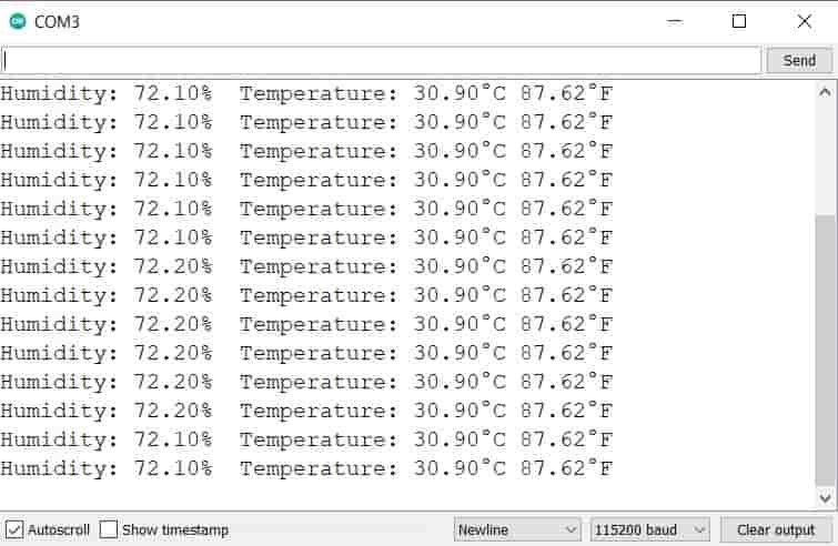
Now open the serial monitor in Arduino IDE, you will see temperature and humidity readings getting displayed after every one second.
ESP32 Display DHT11/DHTT2 Readings on OLED
In this section, we will see how to display DHT11/DHT22 sensor readings such as Temperature, and Humidity values on a 0.96 SSD1306 OLED display using Arduino IDE and ESP32.
Installing SSD1306 OLED Library in Arduino IDE
To use the OLED display in our project, we have to install the Adafruit SSD1306 OLED library in Arduino IDE. Follow the steps below to successfully install it.
Open Arduino IDE and click on Sketch > Library > Manage Libraries
The following window will open up.
Type ‘SSD1306’ in the search tab and install the Adafruit SSD1306 OLED library.

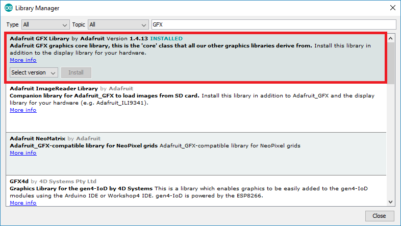
We will also require the Adafruit GFX library which is a dependency for SSD1306. Type ‘Adafruit GFX’ in the search tab and install it as well.
You may like this in-depth guide on OLED interfacing with ESP32:
Schematic – OLED with ESP32 and DHT11/DHT22
This section shows how to connect an ESP32 board with a DHT22 sensor and an OLED display. Connect the DHT22 to ESP32 along with a 10K ohm pull-up resistor. Follow the connections as described in the two tables below.
The tables below show the terminals of the three devices which should be connected together.
| OLED Display | ESP32 |
|---|---|
| VCC | VCC=3.3V |
| GND | GND |
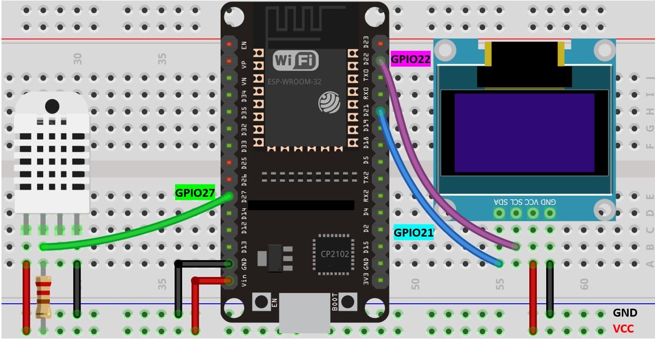
| SCL | GPIO22 |
| SDA | GPIO21 |
| ESP32 | DHT11/DHT22 |
|---|---|
| VCC=3.3V | VCC |
| GND | GND |
| Data | GPIO27 |
Assemble the circuit as shown in the schematic diagram below:
- The first pin is the power supply (VCC) pin. Connect it with the 3.3 volt pin of ESP32.
- Data out is the pin through which we get temperature and humidity samples from the DHT sensor. Connect this pin with GPIO27 of ESP32 and also connect the data pin with a 10k pull-up resistor. You can also use any appropriate digital pin of ESP32.
A Pull-up resistor is used to keep the data pin high for proper communication between the microcontroller and sensor. You can check the datasheet of DHT11 and DHT22 to get more information about it. DHT22 is also known by the name of AM2302.
- Third pin is not used
- Connect the fourth pin (GND) to the ground pin of the ESP32 board
Additionally, we will connect the VCC terminal of the OLED display with 3.3V which will be in common with the ESP32 board. SCL of the display will be connected with the SCL pin of the ESP32 board and the SDA of the display will be connected with the SDA of the ESP32.
Arduino Sketch to Display DHT11 and DHT22 Readings on OLED
Copy the following code to your Arduino IDE and upload it to the ESP32 after assembling the above circuit diagram.
How Code Works?
The maximum portion of the code is the same as we have discussed earlier except for the OLED display part. Therefore, we will only explain the OLED display part here.
Include Libraries
We will first include all the required libraries for the DHT11/DHT22 sensor as well as the OLED display which we just installed before.
Now, we will create another object named display which will be handling the OLED display. Also, define the size of the OLED display by passing arguments to the Adafruit_SSD1306() function.
This block of code initializes the OLED display.
We have set the font size as default which is 1. Whenever we increase the size by +1, the pixel resolution of the text increases by 10 in height. Next, we will control the color of the text by using the setTextColor() function and passing WHITE as an argument. If we have a dark background, we will display our text in white and if we have a bright background then we will display the text in black. We do not want to rotate the text, so we are passing 0 as the parameter inside the setRotation() function. The parameter can take in any value from 0,1,2,3 where 0 denotes rotation of 0 degrees, 1 denotes rotation of 90 degrees, 2 denotes rotation of 180 degrees and 3 denotes a rotation of 270 degrees.
The loop() obtains the readings from the sensors and prints them on the OLED display. The clearDisplay() function wipes off the previous readings from the display after each loop() so that new ones can be printed.
We will use the setCursor() function to denote the x and the y axis position from where the text should start. We have passed (0,0) as the parameter hence the text starts from the upper left corner.
Displaying DHT22 readings on the OLED display
Now let’s display the temperature and humidity values on the serial monitor and OLED one by one. This block of code displays DHT22 sensor values on OLED and updates the value after every 1 second.
In above code, the setTextSize() function is used to set the size of font. We used low size for simple text such as “Temperature” and “Humidity” and high size font to display actual temperature and humidity readings. The setCursor() method defined where we want to display our text on 128×64 OLED. Finally, the print() functions write the text on the defined position.
Demonstration
To see the demonstration of the above code, upload the code to Arduino. But, before uploading code, make sure to select the ESP32 board from Tools > Board and also select the correct COM port to which the ESP32 board is connected from Tools > Port.
Once the code is uploaded to ESP32, open the serial monitor of Arduino IDE and set the baud rate to 115200. Finally, we can see the DHT22 temperature and humidity readings on Arduino serial monitor and on SSD1306 OLED display as follows:

If you want to create a DHT11/DHT22 web server using ESP32, you can check this in-depth project:
If you like this tutorial, you may also like to see other sensors interfacing with ESP32: