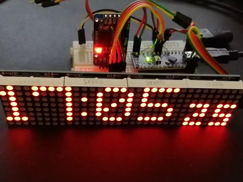
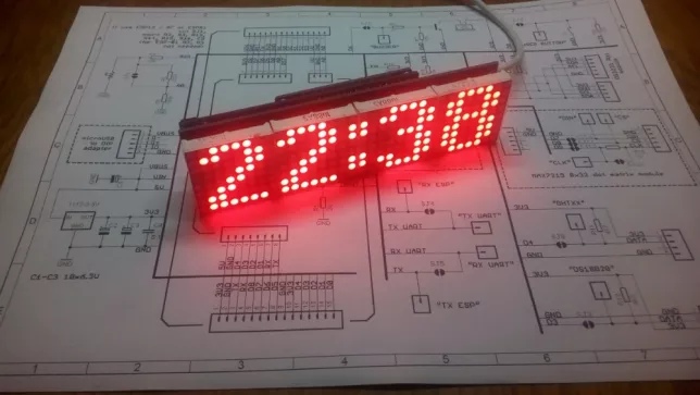
Часы на Arduino Nano и светодиодных матрицах 4×64 LED Matrix
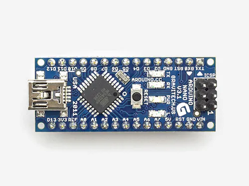
| 03.09.2019, 13:01 Источник: Ардуино радиолюбитель VK Комплектующие для сборки на али: Плата ардуино нано https://ali.pub/3q9jj2 Светодиодные матрицы MAX7219 https://ali.pub/3q9jmk
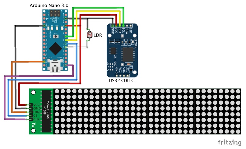
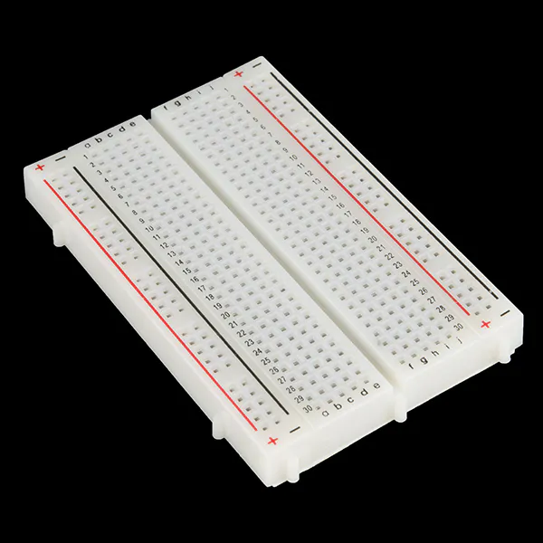
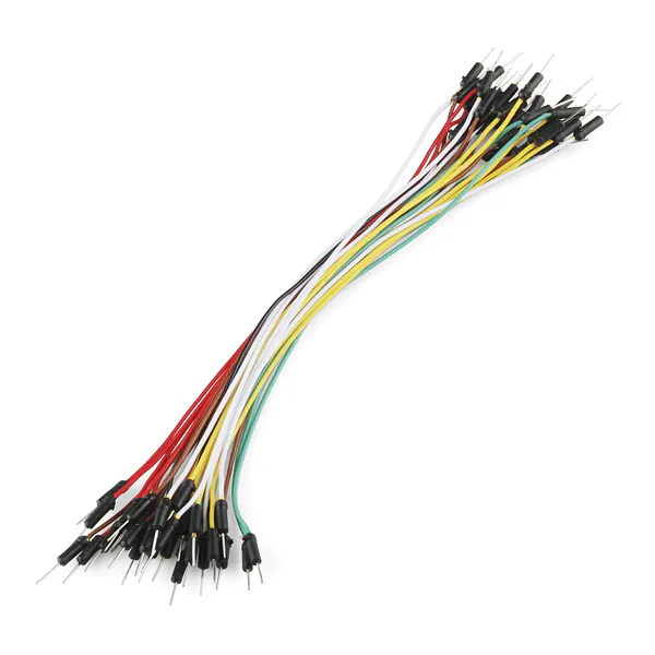
Фоторезистор https://ali.pub/3q9jwa Модуль часов реального времени DS3231 https://ali.pub/3q9jz0 Схема сборки нашего Ардуино проекта
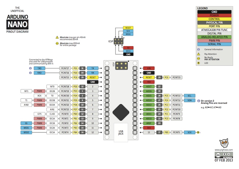
Распиновка ардуино Nano 3.0:
Код прошивки : #include DS3231 rtc(SDA, SCL); // Real time clock const byte LDR_PIN = A2; // LDR Sensor pin #define MAX_DEVICES 4 #define USE_NEW_FONT 1 #define BUF_SIZE 20 // text buffer size char buf[BUF_SIZE], secs[4]; // SPI hardware interface const byte WAIT = 100; iw0rm3r/DS3231_MAX7219_ClockUse Git or checkout with SVN using the web URL. Work fast with our official CLI. Learn more. Launching GitHub DesktopIf nothing happens, download GitHub Desktop and try again. Launching GitHub DesktopIf nothing happens, download GitHub Desktop and try again. Launching XcodeIf nothing happens, download Xcode and try again. Launching Visual Studio CodeYour codespace will open once ready. There was a problem preparing your codespace, please try again. Latest commitGit statsFilesFailed to load latest commit information. README.mdМногофункциональные Arduino-часы на LED матрице с контроллером MAX7219 Программная основа для сборки многофункциональных часов на базе Arduino Uno/nano с использованием модуля часов реального времени DS3231 и LED матрицы из модулей на базе контроллера MAX7219. Для работы с LED матрицей используются собственные функции, составляющие «обёртку» вокруг легковесной библиотеки Faster_LEDControl, т.к. многоцелевые библиотеки управления LED матрицами, вроде MD_Parola, избыточны и не позволяют уместить нужный функционал во flash-память контроллера Arduino Uno. Проект находится на стадии разработки. Функционал, реализованный на данный момент:
Используемые компоненты:
Как использовать?
Структура проекта:
Планируемый функционал:
AboutМногофункциональные Arduino-часы на LED матрице с контроллером MAX7219 7-Segment Clock with Arduino Nano + DS3231 + LDR © LGPLAnother clock project with 1, 2″ matrix display.
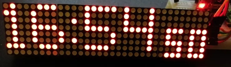
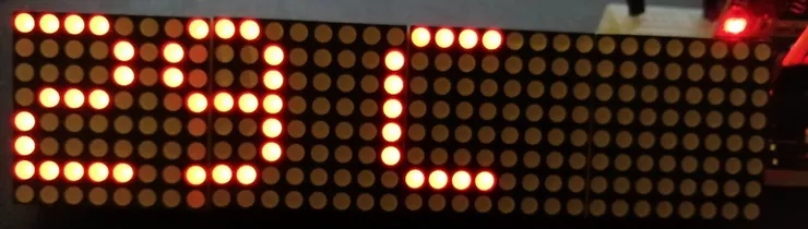
In times where you always have a clock on your wrist, be it a watch on your wrist or a smartphone, the Arduino Uno/Nano is a bit dull. You otherwise have NTP server synchronized devices in this article outside, which are constantly online via your Internet connection. One of my friends refused for personal reasons a device with WiFi connection in his bedroom and so I have the Arduino equipped with a separate clock. Choose the right product I was surprised how many different products even Adafruit had available: depending on the desired tension, as well as with different precision! Here I decided for two products: the cheaper DS1307 and the probably more precise DS3231 . To be clear: both products can be used in this clock. To use the DS1307, pay attention to the correct PIN assignment and the restriction to the temperature display option: remark «//» the displayTemp(); function within the loop(). Adapt the sketch I went looking for a sketch and found something with another member . I restructured and fit this sketch, but kept its Czech comments and added English remarks. The ad was supposed to be as big as possible and so I decided on a 7-segment ad: after all, I only wanted to have the time in mind. The next positive surprise I experienced while reviewing the sketches: here, the DS3231 provides the option to use the temperature , which the DS1307 — in addition to its inaccuracy — missing. Init the Clocks If you have a CR1220 button cell battery, you can follow Adafruit’s short tutorial on setting up the clocks. In summary, the time is not downloaded from the Internet, but over time from the local PC. The upload timestamp is transferred to the timers. Afterwards I added the LED matrix to the circuit for time and temperature output . The period for the change of time and temperature can be set via variables. In particular, how the control of the individual — flashing — dots and digits on the LED matrix works and is controlled, is well described in the sketch. Here I refer to more Adafruit sources . The sketch is rounded off by the adjustment of summer/winter time and the brightness of the LED matrix depending on the ambient light (at night the display should be darker than in daylight). In the video, you certainly noticed the change of time and temperature. Did you pay attention to the point on the left in the picture? This changes its position (up or down) depending on the seconds. Give me feedback if you know how to issue an «ERR» on the LED matrix in case of failure of the clock. At the moment «bEEF» will appear: clockspot/arduino-clockUse Git or checkout with SVN using the web URL. Work fast with our official CLI. Learn more. Launching GitHub DesktopIf nothing happens, download GitHub Desktop and try again. Launching GitHub DesktopIf nothing happens, download GitHub Desktop and try again. Launching XcodeIf nothing happens, download Xcode and try again. Launching Visual Studio CodeYour codespace will open once ready. There was a problem preparing your codespace, please try again. Latest commitGit statsFilesFailed to load latest commit information. README.mdUniversal Arduino Digital Clock
To see your clock’s software version, hold Select briefly while powering up the clock. A universal digital clock codebase for Arduino, maintained by Luke.
Written to support RLB Designs’ Universal Nixie Driver Board (UNDB):
Configuration, compilation, and upload Various options, such as enabled functionality, RTC, display, I/O pins, timeouts, and control behaviors, are specified in a config file. This allows you to maintain configs for multiple clock hardware profiles, and simply include the relevant config at the top of arduino-clock.h before compiling. Several example configs are provided, and sample.h includes all possible options with detailed comments. You may also wish to adjust the defaults for the clock’s user-configurable values to best suit its intended use, in case the user performs a hard reset. Some of these are specified in the config; others, for now, are hardcoded in arduino-clock.ino ( optsDef[] for settings and initEEPROM() for other values). I use the Arduino IDE to compile and upload, due to the use of various Arduino and Arduino-oriented libraries. Make sure the relevant libraries are installed in the Library Manager, per the config in use.
Before compiling and uploading, you will need to select the correct board, port, and (for AVR) processor in the IDE’s Tools menu.
AboutDigital clock code for Arduino Nano and Nano 33 IoT, to drive nixie or LED matrix displays Adblockdetector |