Arduino Nano 33 IoT: распиновка, схема подключения и программирование
Arduino Nano 33 IoT — компактная платформа для разработки с 32-битным микроконтроллером Microchip ATSAMD21G18, беспроводным модулем U-blox NINA-W102 и IMU-сенсором на 6 степеней свободы.
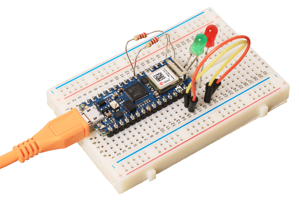
Подключение и настройка
Шаг 1
Скачайте и установите на компьютер интегрированную среду разработки Arduino IDE.
Шаг 2
По умолчанию среда Arduino IDE настроена только на AVR-платы. Для работы с платформой Arduino Nano 33 IoT — добавьте в менеджере плат поддержку платформ на ядре ARM Cortex-M0+.
Элементы платы
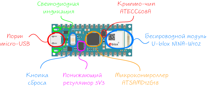
Микроконтроллер ATSAMD21G18
Мозгом платформы Arduino MKR Wi-Fi 1010 является 32-разрядный микроконтроллер фирмы Microchip (Atmel) — ATSAMD21G18 с вычислительном ядром ARM Cortex® M0.
Благодаря использованию 32-разрядного ядра ARM, Arduino Nano IoT во многом превосходит типичные платы на базе 8-разрядных микроконтроллеров. Наиболее существенные отличия заключаются в следующем:
Беспроводной модуль NINA-W102
За беспроводную связь отвечает модуль U-blox NINA-W102 со встроенным чипом ESP32 для обмена данными по воздуху в диапазоне 2,4 ГГц по Wi-Fi и Bluetooth. Регулировка выходной мощности обеспечивает оптимальное соотношение между дальностью связи, скоростью передачи данных и энергопотреблением.
IMU-сенсор
IMU-сенсор на 6 степеней свободы включает в себя акселерометр и компас. Сборка выполнена на чипе LSM6DS3 по технологии (англ. System-in-Package — система в корпусе), где акселерометр и гироскоп лежат методом бутерброда в пластиковом корпусе.
Крипто-чип ATECC608A
Криптографический сопроцессор Microchip ATECC608A интегрирует протокол безопасности ECDH (Elliptic Curve Diffie Hellman) в сверхзащищенный метод, обеспечивающий согласование ключей для шифрования / дешифрования, наряду с ECDSA (алгоритм цифровой подписи эллиптической кривой) для проверки подлинности с подписью для Интернета вещей (IoT), включая домашнюю автоматизацию, промышленные сети, медицинские услуги, аутентификацию аксессуаров и расходных материалов.
USB порт
Разъём micro-USB предназначен для прошивки платформы Arduino Nano Every с помощью компьютера.
Светодиодная индикация
| Имя светодиода | Назначение |
|---|---|
| ON | Информационный индикатор питания |
| L | Пользовательский светодиод на 13 пине микроконтроллера. Используйте определение LED_BUILTIN для работы со светодиодом. При задании значения высокого уровня светодиод включается, при низком – выключается. |
Понижающий регулятор 3V3
Импульсный понижающий регулятор напряжения MPM3610 обеспечивает питание микроконтроллера ATSAMD21G18 и другой логики платформы при подключении платформы через пин Vin . Диапазон входного напряжения от 5 до 18 вольт. Выходное напряжение 3,3 В с максимальным выходным током 1,2 А.
Кнопка RESET
Пользовательская кнопка с двумя полезными функциями:
Распиновка
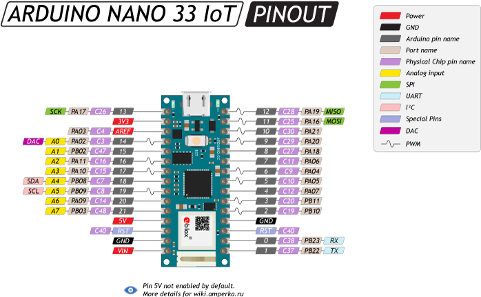
Пины питания
Порты ввода/вывода
В отличии от большинство плат Arduino, родным напряжением Arduino Nano 33 IoT является 3,3 В, а не 5 В. Выходы для логической единицы выдают 3,3 В, а в режиме входа ожидают принимать не более 3,3 В. Большее напряжение может повредить микроконтроллер!
Будьте внимательны при подключении периферии: убедитесь, что она может корректно функционировать в этом диапазоне напряжений.
Getting started with the Arduino Nano 33 IoT
Arduino Nano 33 IoT board has been designed to offer a practical and cost effective solution for makers seeking to add Wi-Fi connectivity to their projects with minimal previous experience in networking. Learn how to set up the programming environment and get the hardware up and running, ready for your projects, in minutes.
The Arduino Nano 33 IoT is programmed using the Arduino Software (IDE), our Integrated Development Environment common to all our boards and running both online and offline. For more information on how to get started with the Arduino Software visit the Getting Started page.
Use your Arduino Nano 33 IoT with the Arduino IoT Cloud
This board is compatible with the Arduino IoT Cloud, where you can create IoT applications in a few simple steps. The cloud includes powerful features, such as building dashboards to monitor and control sensor networks, while making sure your data is secure.
Getting started is quick and easy, and requires just three simple steps:
- Create an Arduino Create account here.
- Download and install the Arduino Create plugin here.
- Go to Arduino IoT Cloud and start your journey through IoT!
Use your Arduino Nano 33 IoT on the Arduino Web IDE
All Arduino boards, including this one, work out-of-the-box on the Arduino Web Editor, you only need to install Arduino Create Agent to get started.
The Arduino Web Editor is hosted online, therefore it will always be up-to-date with the latest features and support for all boards. Follow this simple guide to start coding on the browser and upload your sketches onto your board.
Use your Arduino Nano 33 IoT on the Arduino Desktop IDE
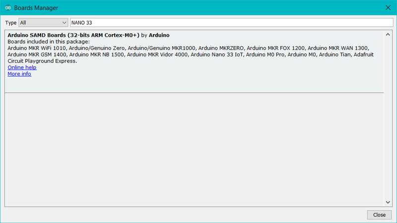
If you want to program your Arduino Nano 33 IoT while offline you need to install the Arduino Desktop IDE and add the Arduino SAMD Core to it. This simple procedure is done selecting Tools menu, then Boards and last Boards Manager, as documented in the Arduino Boards Manager page.
Installing Drivers for the Arduino Nano 33 IoT
With the SAMD core installed, you now proceed with the driver installation.
OS No driver installation is necessary on OS. Depending on the version of the OS you’re running, you may get a dialog box asking you if you wish to open the «Network Preferences». Click the «Network Preferences. » button, then click «Apply». The Arduino Nano 33 IoT will show up as «Not Configured», but it is still working. You can quit the System Preferences.
Windows (tested on 7, 8 and 10) If you properly installed the SAMD Core, just connect the Arduino Nano 33 IoT to your computer with a USB cable. Windows should initiate its driver installation process once the board is plugged in.
Linux No driver installation is necessary for Linux.
Open your first sketch
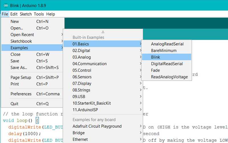
Open the LED blink example sketch: File > Examples >01.Basics > Blink.
Select your board type and port
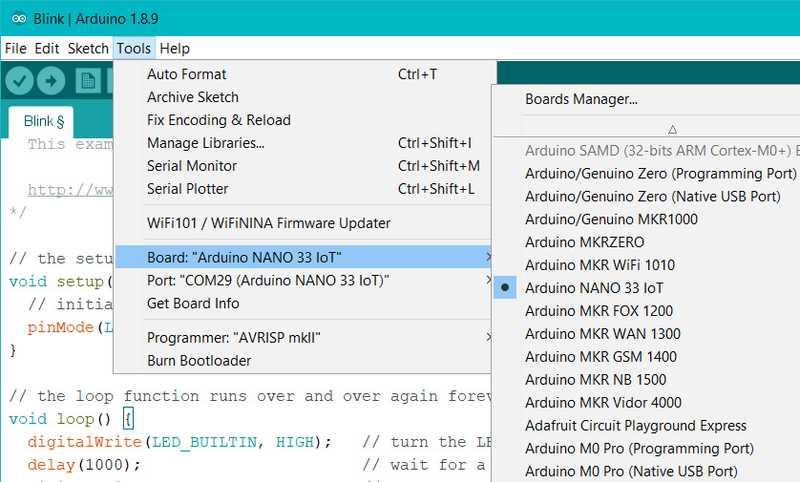
You’ll need to select the entry in the Tools > Board menu that corresponds to your Arduino board.
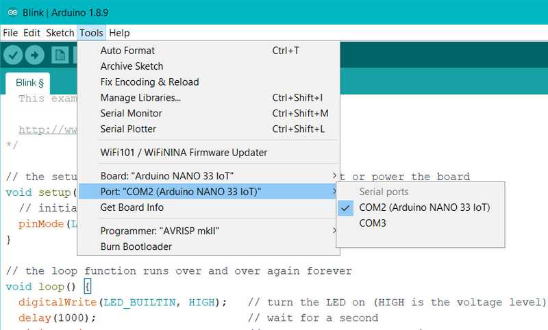
Select the serial device of the board from the Tools | Serial Port menu. This is likely to be COM2 or higher (COM1 is usually reserved for hardware serial ports). To find out, you can disconnect your board and re-open the menu; the entry that disappears should be the Arduino board. Reconnect the board and select that serial port.
Upload the program
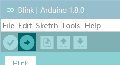
Now, simply click the «Upload» button in the environment. Wait a few seconds — you should see the green progress bar on the right of the status bar. If the upload is successful, the message «Done uploading.» will appear on the left in the status bar.
A few seconds after the upload finishes, you should see the on-board LED start to blink (in orange). If it does, congratulations! You’ve gotten your Arduino Nano 33 IoT up-and-running. If you have problems, please see the troubleshooting suggestions.
Learn more on the Desktop IDE
See this tutorial for a generic guide on the Arduino IDE with a few more infos on the Preferences, the Board Manager, and the Library Manager.
Tutorials
Now that you have set up and programmed your Arduino Nano 33 IoT board, you may find inspiration in our Project Hub tutorial platform or have a look to the tutorial pages that explain how to use the various features of your board.
Here are a few tutorials that will help you in making cool things with the SAMD and WiFi features of the board!
Please Read.
The microcontroller on the Arduino Nano 33 IoT runs at 3.3V, which means that you must never apply more than 3.3V to its Digital and Analog pins. Care must be taken when connecting sensors and actuators to assure that this limit of 3.3V is never exceeded. Connecting higher voltage signals, like the 5V commonly used with the other Arduino boards, will damage the Arduino Nano 33 IoT.
To avoid such risk with existing projects, where you should be able to pull out a Nano and replace it with the new Nano 33 IoT, we have the 5V pin on the header, positioned between RST and A7 that is not connected as default factory setting. This means that if you have a design that takes 5V from that pin, it won’t work immediately, as a precaution we put in place to draw your attention to the 3.3V compliance on digital and analog inputs.
5V on that pin is available only when two conditions are met: you make a solder bridge on the two pads marked as VUSB and you power the Nano 33 IoT through the USB port. If you power the board from the VIN pin, you won’t get any regulated 5V and therefore even if you do the solder bridge, nothing will come out of that 5V pin. The 3.3V, on the other hand, is always available and supports enough current to drive your sensors. Please make your designs so that sensors and actuators are driven with 3.3V and work with 3.3V digital IO levels. 5V is now an option for many modules and 3.3V is becoming the standard voltage for electronic ICs.
Features
Serial ports on the Arduino Nano 33 IoT
The USB connector of the board is directly connected to the USB host pins of the SAMD21. This routing enables you to use the Arduino Nano 33 IoT as a client USB peripheral (acting as a mouse or a keyboard connected to the computer) or as a USB host device so that devices like a mouse, keyboard, or an Android phone can be connected to the Arduino Nano 33 IoT. This port can also be used as a virtual serial port using the Serial object in the Arduino programming language. The RX0 and TX1 pins are a second serial port available as Serial1.
ADC and PWM resolutions
The Arduino Nano 33 IoT has the ability to change its analog read and write resolutions (defaults to 10-bits and 8-bits, respectively). It can support up to 12-bit ADC/PWM and 10-bit DAC resolutions. See the analog write resolution and analog read resolution pages for more information.
WiFi on the Arduino Nano 33 IoT
This board is fully compatible with the WiFiNINA library and all the examples made for it.
IMU on the Arduino Nano 33 IoT
The IMU is a LSM6DS3, it is a 3-axis accelerometer and 3-axis gyroscope. and it is connected to the SAMD through I2C. This chip, made by ST Microelectronics, is a standard component that you can use with our own library Arduino_LSM6DS3. To get the library, you can use our Library Manager available in the Arduino Software (IDE) .
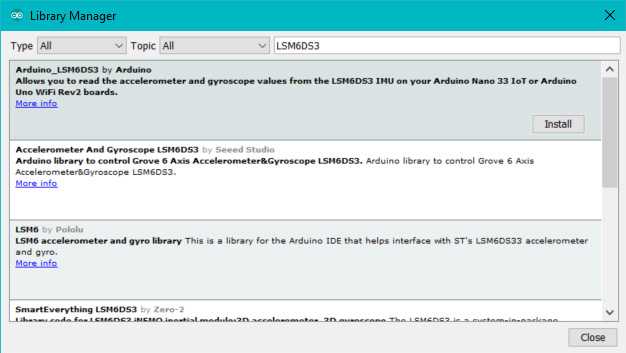
The library contains two examples to show you how to read acceleration and rotational speed.
For more details on the Arduino Nano 33 IoT, see the product page.
The text of the Arduino getting started guide is licensed under a Creative Commons Attribution-ShareAlike 3.0 License. Code samples in the guide are released into the public domain.
Controlling a LED Through BluetoothВ® with Nano 33 IoT
AUTHOR: Fabricio Troya
LAST REVISION: 10/05/2022, 01:00 PM
In this tutorial we will use an Arduino Nano 33 IoT to turn on the built-in LED over Bluetooth, made possible by the NINA module embedded on the board.
Goals
The goals of this project are:
- Learn what BluetoothВ® Low Energy and BluetoothВ® are.
- Use the Arduino BLE library.
- Learn how to create a new service.
- Learn how to control a LED from an external device (smartphone).
Hardware & Software Needed
- This project uses no external sensors or components.
- In this tutorial we will use the Arduino Web Editor to program the board.
BluetoothВ® Low Energy and BluetoothВ®
Bluetooth® Low Energy, referred to as Bluetooth® Low Energy, separates itself from what is now known as “Bluetooth® Classic” by being optimized to use low power with low data rates. There are two different types of Bluetooth® devices: central or peripheral. A central Bluetooth® device is designed to read data from peripheral devices, while the peripheral devices are designed to do the opposite. Peripheral devices continuously post data for other devices to read, and it is precisely what we will be focusing on this tutorial.
Service & Characteristics
A service can be made up of different data measurements. For example, if we have a device that measures wind speed, temperature and humidity, we can set up a service that is called “Weather Data”. Let’s say the device also records battery levels and energy consumption, we can set up a service that is called “Energy information”. These services can then be subscribed to central Bluetooth® devices.
Characteristics are components of the service we mentioned above. For example, the temperature or battery level are both characteristics, which record data and update continuously.
Unique Universal Identifier (UUID)
When we read data from a service, it is important to know what type of data we are reading. For this, we use UUIDs, who basically give a name to the characteristics. For example, if we are recording temperature, we want to label that characteristic as temperature, and to do that, we have to find the UUID, which in this case is “2A6E”. When we are connecting to the device, this service will then appear as “temperature”. This is very useful when tracking multiple values.
If you want to read more about UUIDs, services, and characteristics, check the links below:
Creating the Program
1. Setting up
Let’s start by opening the Arduino Web Editor, click on the Libraries tab and search for the ArduinoBLE library. Then in Examples > Peripheral, open the LED sketch and once it opens, you could rename it as desired.
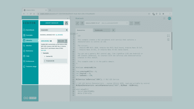 Finding the library in the Web Editor.
2. Connecting the board
Now, connect the Arduino Nano 33 IoT to the computer and make sure that the Web Editor recognizes it, if so, the board and port should appear as shown in the image below. If they don’t appear, follow the instructions to install the plugin that will allow the Editor to recognize your board.
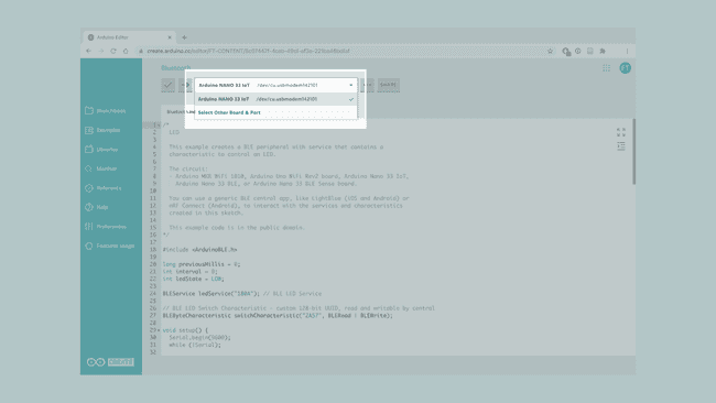 Selecting the board.
3.Turning ON the LED
Now we will need to modify the code on the example, in order to control LED, based on the information we sent through the smartphone.
After including the library, in the function change the argument to which is translated to «Device Information». Then in the function change the argument to which is translated to «Digital Output».
In the after initializing the serial communication we set the LED pin as .
Then, inside the function, we need to go to the and change the name to in order to identify the board we are using.
Now, in the , we replace the second function inside the loop with a function, where each case will control the LED in a different manner:
- The default case will keep the LED OFF
- Case 01 will turn the LED ON
- Case 02 will blink the LED each 500 ms
- Case 03 will blink the LED each second
Lastly, after the last function we use the to turn off the LED once the phone is disconnected from the board.
4. Complete code
If you choose to skip the code building section, the complete code can be found below:
Testing It Out
Once we are finished with the coding, we can upload the sketch to the board. When it has successfully uploaded, open the Serial Monitor. In the Serial Monitor, the text «BLE LED Peripheral» will appear as seen in the image below.
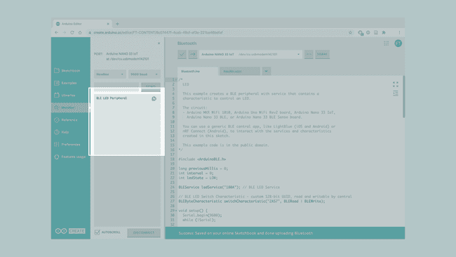 Serial Monitor output.
We can now discover our Nano 33 IoT board in the list of available BluetoothВ® devices. To access the service and characteristic we recommend using the LightBlue application. Follow this link for iPhones or this link for Android phones.
Once we have the application open, follow the image below for instructions:
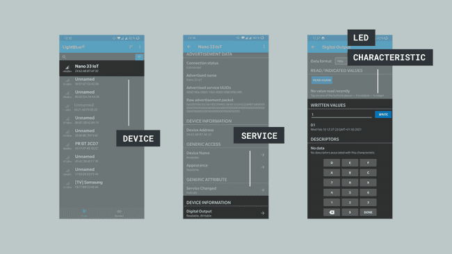 Accessing through a BluetoothВ® phone app.
To control the LED, we simply need to write 1,2 or 3 in the «WRITTEN VALUES» field to turn on the LED, make the LED blink fast or slow and any other value to turn them off. This is within the «Digital Output» characteristic, which is located under «Device Information».
Troubleshoot
Sometimes errors occur, if the code is not working there are some common issues we can troubleshoot:
- Missing a bracket or a semicolon.
- Arduino board connected to the wrong port.
- We haven’t opened the Serial Monitor to initialize the program.
- The device you are using to connect has its BluetoothВ® turned off.
Conclusion
In this tutorial we have created a basic BluetoothВ® peripheral device. We learned how to create services and characteristics, and how to use UUIDs from the official BluetoothВ® documentation. Lastly, we control the LED based on the values sent from the smartphone.
Now that you have learned a little bit how to use the ArduinoBLE library, you can try out some of our other tutorials for the Nano 33 IoT. You can also check out the ArduinoBLE library for more examples and inspiration for creating BluetoothВ® projects!