LCD Custom Character © MIT
Custom character coding for a LCD without using potentiometer
This project helps to code a LCD efficiently without the use of potentiometer. The main objective is to do custom charecter coding.
Use the following link to make your own custom character: https://omerk.github.io/lcdchargen/
CIRCUIT CODEArduino
CIRCUIT FRAMEWORK

RESULT
Please log in or sign up to comment.
Author

GHOSTYN2512
- 1 project
- 0 followers
Additional contributors
- Thank for such a wonderful circuit. by Pawandeep Singh
Published on
Members who respect this project


Table of contents
Similar projects you might like
![]()
Easily display custom animated glyphs on 16×2 LCD using the createChar() function from the LiquidCrystal library.
Create Custom Animations on 16×2 LCD Displays
Project tutorial by tusindfryd
- 11,198 views
- 28 comments
- 60 respects
![]()
In this I will tell you how to connect two 16*2 LCD together with single arduino. This is a very unique project. you can’t find this anywhere.
How to connect two 16*2 LCD together with arduino
Project tutorial by Shashwat Raj
![]()
Just a basic sound sensor activated LEDs with an optional LCD for sound level data. ***STROBE LIGHT EFFECT AT AROUND 8:45 MINUTE MARK!***
Sound Sensor Activated LEDs with LCD for Sound Level Data!
Project tutorial by HeathenHacks
- 16,842 views
- 10 comments
- 29 respects
![]()
A fun game for your Arduino using an LCD, joystick and buzzer.
rwbl/lcd-custom-char-maker
Use Git or checkout with SVN using the web URL.
Work fast with our official CLI. Learn more.
Launching GitHub Desktop
If nothing happens, download GitHub Desktop and try again.
Launching GitHub Desktop
If nothing happens, download GitHub Desktop and try again.
Launching Xcode
If nothing happens, download Xcode and try again.
Launching Visual Studio Code
Your codespace will open once ready.
There was a problem preparing your codespace, please try again.
Latest commit
Git stats
Files
Failed to load latest commit information.
README.md
Create Custom Characters for LCD displays connected to Arduino, Raspberry Pi, Tinkerforge or other
- Created with B4J v8.00 — development tool for cross platform desktop, server and IoT solutions.
- Requires Java JDK 8 to run. Ensure to comply to the Oracle JDK Licence agreement.
- Developed for personal & development use only.

- Create custom LCD character with 5 pixel horizontal (cols), 8 pixel vertical (rows).
- Each row is represented by a byte with 5 bits.
- Create DEC, HEX and BIN arrays.
- Save / open the character to / from a textfile located in the application folder.
- Import 8 bytes array string in format 0xNN,0xNN. where NN is HEX value.
- Convert LCD character table high & low bits to DEC & HEX values.
- Various language specific examples
- Some example chars in the project source/objects folder.
- lcdcustomcharmaker.zip contains the application, sample characters and examples.
From the source/Objects folder, run the Java jar lcdcustomcharmaker.jar
Notes:
- The full B4J source code is included (folder source).
- An example batch file «run8.bat» to run under Windows is included. Ensure to set the path to the JDK8 folder.
- There is also a «run11.bat» for running with openJDK11 — might require to recompile first with B4J using openJDK11.
Example Coding Custom Character Battery
This example covers various development tools B4R, B4J and dedicated Tinkerforge 20×4 bricklet with C, Java, JavaScript, MQTT & Python.
Example output for the custom character Battery (empty):
The LCD 20×4 Bricklet supports up to 8 custom characters 0-7 which are mapped to \u0008-\u000F (\u takes hex numbers). Tested defining and writing custom characters with an LCD 20×4 v1.2 Bricklet having UID=BHN. Some API snippet exmples.
Test 1: Turn the display backlight on, clear the display and display text string «Hello World».
Test 2: Define & custom character Battery.
The JSON definition for the custom character battery set to index 0 (the first custom character at position 0x08 = \u0008):
Set custom character 0:
Write it to the display with some text:
B4R Binary Definition
InlineC Code is required to display the special characters. This example can be used by copy and paste in projects.
To write a character from the character table of the LCD Display driver. The Degree Character ° is located at position upper 4 bits 1101 and lower 4 bits 1111. The 8 bits 1101 1111 are HEX DF and DEC 223. To write the character to the LCD use lcd.Write(Array As Byte(223)).
LCD Character Table
Convert Upper 4 & Lower 4 bits to HEX and Unicode Example Cent Character: Upper 4 bits = 1110, Lower 4 bits = 1111 Converted: 11101111 = EF , 0xEF , \u00EF, 239
Use the LCD display datasheet accordingly.
This program is free software: you can redistribute it and/or modify it under the terms of the GNU General Public License as published by the Free Software Foundation, either version 3 of the License, or (at your option) any later version. This program is distributed in the hope that it will be useful, but WITHOUT ANY WARRANTY; without even the implied warranty of MERCHANTABILITY or FITNESS for A PARTICULAR PURPOSE. See the GNU General Public License for more details. You should have received a copy of the GNU General Public License along with the samples. If not, see GNU Licenses.
About
Application to create custom characters for LCD displays.
How to generate and display self made Custom characters on 16×2 lcd
This tutorial is about making/building your own characters/special images and then displaying them on character 16×2 lcd. Generating custom characters or special character images and displaying on lcds of any sizes (16×1,16×2,8×1,8×2,20×1,20×2,40×1,40×2 etc) is not a very hard task. One must go through the internal structure of lcd control set in order to know how the character lcd works? Once you know how the lcd works and what features it offers. Then you can easily build and display characters of your desire on lcd screen in a defined matrix.
It requires only knowledge of CG-RAM(character generated ram) of character lcd and the lcd chip set controller to build and display self made characters on 16×2 lcd display. Most of the lcds contains HD4478 controller in them. HD4478 controller is build by Hitachi and its the most popular controller used in the character lcd’s. Almost all of the character lcd’s resides one, but new competitors are also present in market.
By custom characters i mean characters that are not present in the ASCII character set of lcd controller. Like heart symbol, smiley 😀 🙁 ;D :-d 😉 etc. We have to declare these custom characters in CG-RAM of lcd by our own. This tutorial will teach you how to declare custom characters in CG-RAM and then call display them one by one to display on 16×2 lcd screen.
What is
CG-RAM
CG-RAM is the main component in making custom characters. CG stands for custom generated and RAM you all know random access memory. This CG-RAM stores our custom characters once we declare them in our code. I will come on it later. As you know once we write any type of code we need a memory to store it and a controller to run it. In the 16×2 lcd custom character case its same. We write code(arrays) of character’s which we want to display on lcd. Then we store them in a memory on lcd. In our case this memory is named as CG-RAM(Character generated RAM).
CG-RAM size is 64 Bytes. You can create 8 characters at a time and load them in cg-ram. Each character occupies 8-bytes. Eight characters each of eight byte (8-characters * 8-Bytes) is equal to 8×8=64 Bytes. CG-RAM address in lcd memory starts from 0x40(Hexadecimal) or 64 in decimal.
You can place your first character in address ranging from 0x40 to 0x47. The address moves on by 8 bytes for each character for 2nd character address starts from 0x48 and goes to 0x4F. Last eight’t character address starts from 0x78 and goes to 0x7F.
We generate and put our self made custom characters at these addresses. Once we generate our characters at these address now we can print them on lcd at any time by just sending simple commands to lcd controller. Below is the table in which characters addresses and their printing commands are given.

How to Generate and place Custom Characters in CG-RAM?

Declaring character bits against CG-RAM addresses
Here is a simple example on how to generate pixels array for letter ‘b‘ and then place it in CG-RAM of character 16×2 lcd display.
The Array for generating letter ‘b‘ is
char b[7]=<0x10,0x10,0x16,0x19,0x11,0x11,0x1E>;
We now have some online websites through which you can get array of your desired image in 5×7 or 5×8 format. One of the most popular is maxpromer. You can graphically input your desired image on a matrix in maxpromer and then with a single button press you get the array of the image. The array can further be used in your code.

In the above picture you can see the interface of maxpromer. Pretty simple and easy to use. In just seconds you can generate the matrix array for your input character. Array can be generated in binary as well as hexadecimal format.
What individual bits represent in array really needs to be understood. ‘0‘ represents pixel is off and ‘1‘ represent pixel is on. Like for the letter ‘b‘ whose array was highlighted above. Its representation is given below. For each row we have a binary or hexadecimal representation. In binary representation we ignore the 3 MSB or most significant bits, because the coulombs of the matrix are 5. So 5 LSB least significant bits are considered. Also in hexadecimal representation the 3 MSB don’t matter. In the below picture the array of letter ‘b‘ is placed against address ranging from 0x40 to 0x47. Row-1 is placed at address 0x40, row-2 is placed at 0x41, then row-3 is placed at 0x42 and so on until row-7 against address 0x47.

Sample c++ code to generate custom character in cg-ram
The above task is just a simple demo. We properly have to select the data and command registers of lcd in order to place the custom image in CG-RAM.
Important: Just to let you know that commands(like 0x40 address of cg-ram) are send to command register of lcd and data like ‘b‘ pattern is send to data register of lcd.
The above code can be divide in to steps
- Send cg-ram character starting address where you want to create character. I send 0x40 in the above code which means i am placing character in first location.
- Now put your character at this address. Send the ‘b‘ character array string defined above one by one to data register of lcd.
- To print the generated character at 0x40. Send command 0 to command register of lcd.
Visit some projects which i created using different microcontrollers to display custom self made characters on lcd screen. These projects will help you to understand what command and data registers means and how to select them? Projects contains free source code and circuit diagrams.
Arduino — LCD
In this Arduino LCD tutorial, we will learn how to connect an LCD (Liquid Crystal Display) to the Arduino board. LCDs are very popular and widely used in electronics projects for displaying information. There are many types of LCD. This tutorial takes LCD 16×2 (16 columns and 2 rows) as an example. The other LCDs are similar.
If you want to simplify the wiring, You can use LCD I2C instead. See LCD I2C tutorial
Hardware Required
| 1 | × | Arduino UNO or Genuino UNO |
| 1 | × | USB 2.0 cable type A/B |
| 1 | × | LCD |
| 1 | × | Potentiometer |
| 1 | × | Breadboard |
| n | × | Jumper Wires |
About LCD 16×2
Pinout
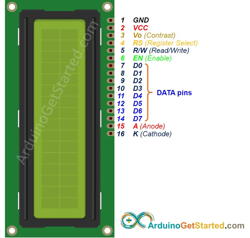
LCD has up to 16 pins. In the most common uses, we do NOT use all pins.
With the support of LiquidCrystal library, we even can use LCD WITHOUT knowing the meaning of these pins. However, if you are curious or want to know in-depth, let’s see these pins and their functionality:
4-bit mode and 8-bit mode
8-bit mode is faster than the 4-bit mode, but use more pins than 4-bit mode. The mode selection is performed at the initialization process by sending a command to LCD.
This tutorial uses 4-bit mode, which is the most common-used.
In this mode, LCD’s pins:
LCD pin table in 4-bit mode
| LCD PIN | CONNECTED TO | |
|---|---|---|
| 01 | GND | GND |
| 02 | VCC | 5V |
| 03 | Vo | 5V or potentiometer’s pin |
| 04 | RS | An Arduino’s pin |
| 05 | R/W | GND |
| 06 | EN | An Arduino’s pin |
| 07 | D0 | NOT connected |
| 08 | D1 | NOT connected |
| 09 | D2 | NOT connected |
| 10 | D3 | NOT connected |
| 11 | D4 | An Arduino’s pin |
| 12 | D5 | An Arduino’s pin |
| 13 | D6 | An Arduino’s pin |
| 14 | D7 | An Arduino’s pin |
| 15 | A | 5V |
| 16 | K | GND |
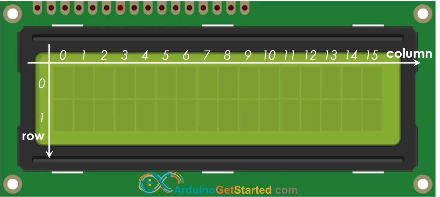
LCD Coordinate
LCD 16×2 includes 16 columns and 2 rows. the conlums and rows are indexed from 0.
How It Works
The process of sending data (to be displayed) to LCD:
The process of sending command (to control) to LCD (e.g, blink LCD, set the cursor to a specific location, clear the display . ):
Arduino — LCD
Controlling LCD is a quite complicated task. Fortunately, thanks to the LiquidCrystal library, this library simplifies the process of controlling LCD for you so you don’t need to know the low-level instructions. You just need to connect Arduino to LCD and use the functions of the library. The using LCD is a piece of cake.
Wiring Diagram

Image is developed using Fritzing. Click to enlarge image