Матричная мембранная клавиатура

Разберём работу с матричной клавиатурой. В моём распоряжении клавиатура размером 4х4, поэтому код будет писаться под неё.
Также могут попадаться клавиатуры с матрицей 4х3 и 4х1 и другие.
Клавиатура состоит из кнопок в виде герметичной панельки из прорезиненного материала. Задняя сторона сделана на самоклеящейся основе, что позволяет легко закрепить панель. Причём, панель гнётся, поэтому её можно прилепить даже на кружку. Клавиатуры герметичны, гибки и долговечны. Они не боятся воды, жары и выдерживают миллион нажатий.
Клавиатура выполнена в виде матрицы 4х4, каждая кнопка является областью воздушного зазора между двумя диэлектрическими слоями с нанесёнными на них токопроводящими покрытиями. Дорожки токопроводящего покрытия одного слоя нанесены горизонтально (выводы 1-4), а другого вертикально (выводы 5-8). Нажатие на кнопку приводит к соединению дорожки одного слоя с дорожкой другого, и как следствие, к замыканию одного из выводов 1-4 с одним из выводов 5-8.
Технические характеристики
- Размеры: 68×77×0,8 мм
- Рабочее напряжение: до 12 В
- Максимальный ток: 100 мА
- Сопротивление изоляции: >100 МОм
- Сопротивление контактов: set(password) Устанавливает пароль is(password) Совпадает ли текущий набор пароля с установленным паролем append(character) Добавляет символ к текущему вводу пароля reset() Сбрасывает набранный ввод пароля evaluate() Совпадает ли текущий набор пароля с установленным паролем
Скетч для ввода пароля
В скетче устанавливается пароль «1234». Максимальное число ввода символов — 6. Если это число будет превышено, то автоматически сравниваем введённый набор с паролем и выдаём результат, сбрасывая ввод. Это избавит нас от бесконечного ввода.
Клавиши «A», «B», «C» ничего не делают, их можно не трогать. Для проверки пароля нужно нажать набор чисел и затем кнопку # (решётку). В успешном случае выводится сообщение OK, в противном случае появится сообщение о неправильном пароле.
Остальные кнопки меняют пароль (на 123), сбрасывают введённый пароль для повторного набора (если заметил ошибку при наборе).
На основе этого скетча можно написать свою логику. Также можно добавить запоминание нового пароля в долговременную память и т.д.
Если вам нужные несколько паролей, то создавайте разные экземпляры.
Arduino — Keypad
The keypad is widely used in many devices such as door lock, ATM, calculator.
In this tutorial, we will learn:
Hardware Required
About Keypad
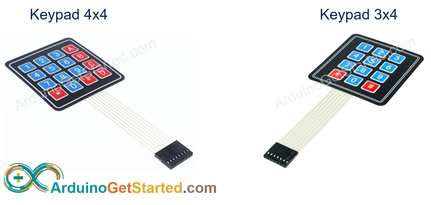
The keypad is a set of buttons arranged in rows and columns (called matrix). Each button is called key
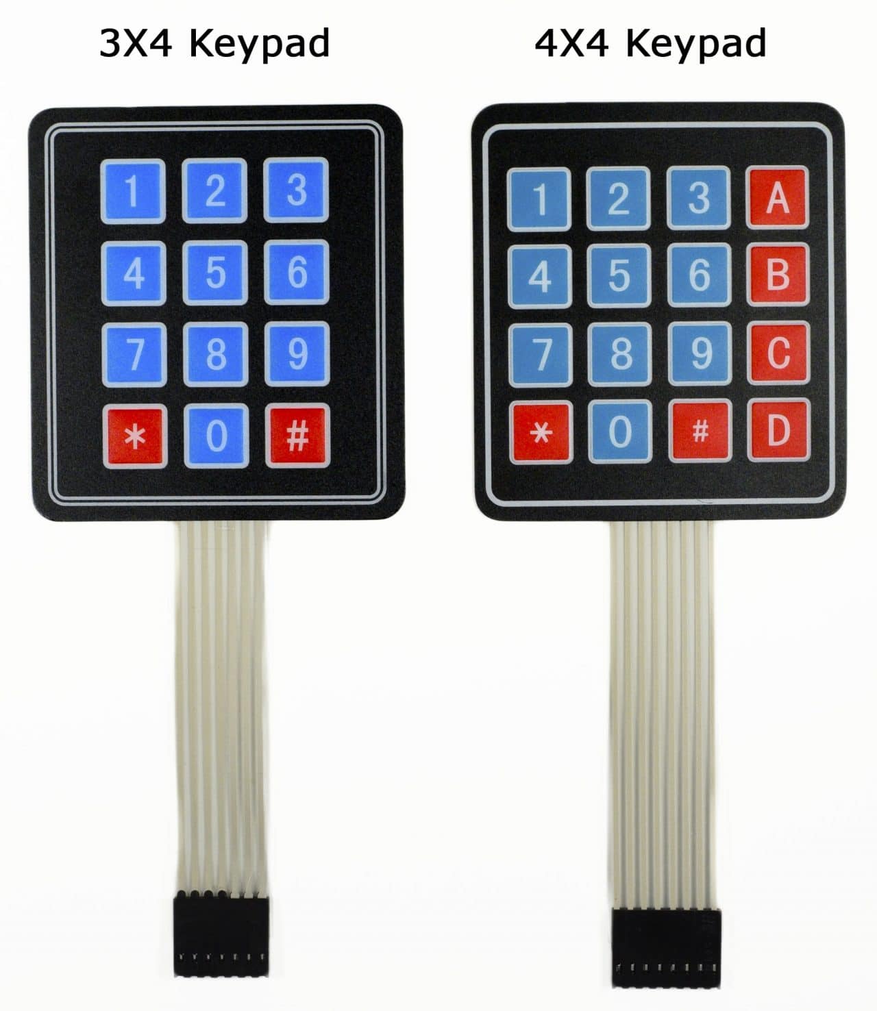
Keypad has various types. Two popular types for DIY projects are keypad 3×4 (12 keys) and keypad 4×4 (16 keys).
Pinout
Keypad pins are divided into two groups: row and column.
Keypad 3×4 has 7 pins: 4 row-pins (R1, R2, R3, R4) and 3 column-pin (C1, C2, C3).
Keypad 4×4 has 8 pins: 4 row-pins (R1, R2, R3, R4) and 4 column-pin (C1, C2, C3, C4).
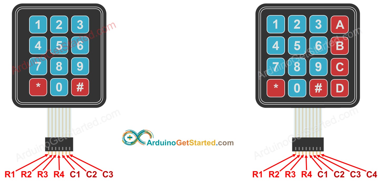
How It Works
The process of detecting the key pressing is called scanning keypad.
It is called “scanning” because it checks one key by one key.
Row-pins are connected to Arduino’s output pins
Column pins are connected to Arduino’s input pins (INPUT_PULLUP, in this state, the value of the input pin is HIGH if the key is not pressed).
The above is one of the methods to scan keypad. We can invert all HIGH to LOW and all LOW to HIGH to scan keypad.
⇒ As we know, an independent button requires one Arduino’s pin and GND . Let’s take keypad 4×4 as an example. If we each key as an independent button, it requires 16 Arduino pin for 16 keys plus GND pin. If we arranged a connected key in matrix form, we just need to use 8 Arduino’s pin, so we can save Arduino’s pin. In short, the answer is: to save the Arduino pins.
Wiring Diagram
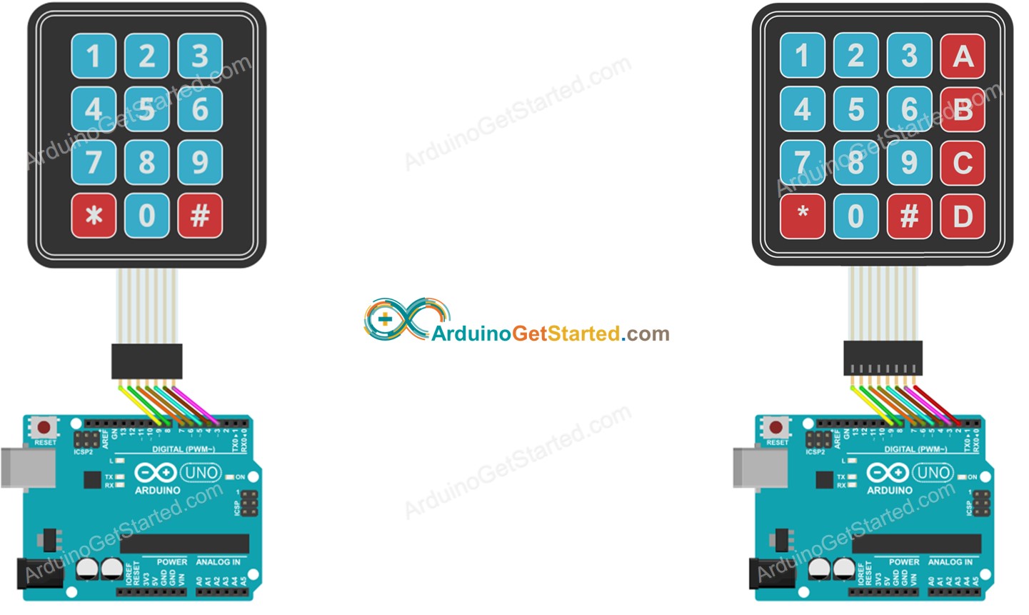
Image is developed using Fritzing. Click to enlarge image
How To Program For Keypad
Thanks to Keypad library, using keypad with Arduino is a piece of cake, no matter whether you understand how the keypad works or not.
Использование клавиатуры совместно с Arduino
Клавиатуры позволяют пользователям вводить данные во время выполнения программы. Данная статья показывает вам, как подключить к Arduino 12-кнопочную клавиатуру, и как использовать библиотеку Keypad.h.
Клавиатура часто требуется для обеспечения ввода данных в систему на Arduino, и мембранные клавиатуры являются экономичным решением для многих приложений. Они довольно тонкие и могут быть легко установлены везде, где они необходимы.
В данной статье мы покажем, как использовать 12-кнопочную цифровую клавиатуру, похожую на ту, что вы можете увидеть на телефоне. 12-кнопочная клавиатура имеет три столбца и четыре строки. Нажатие кнопки замыкает вывод одной из строк с выводом одного из столбцов. Из этой информации Arduino может определить, какая кнопка была нажата. Например, когда нажата кнопка 1, замкнуты столбец 1 и строка 1. Arduino определит это и введет в программу 1.
На рисунке ниже показано, как внутри клавиатуры расположены строки и столбцы.
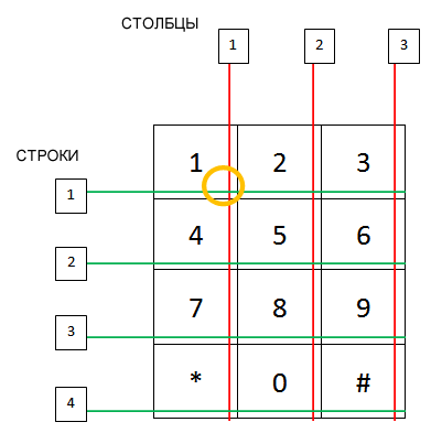 Матричная клавиатура
Эксперимент
В данном эксперименте мы продемонстрируем работу с библиотекой » keypad.h » для Arduino. Когда пользователь нажимает на кнопку на клавиатуре, программа отображает соответствующее значение в мониторе последовательного порта.
Необходимые комплектующие
Схема соединений
Подключите клавиатуру к плате Arduino, как показано на рисунке ниже.
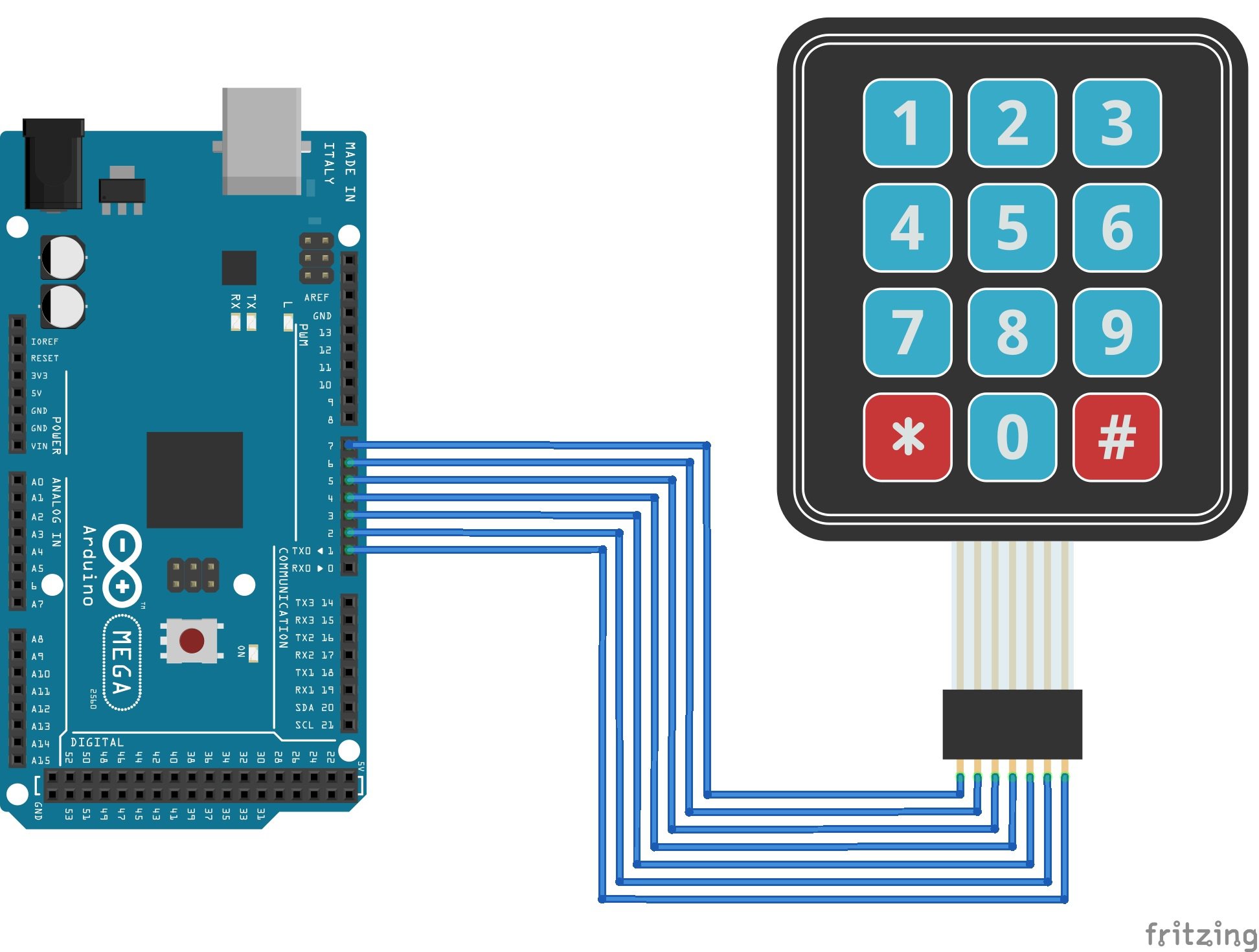 Схема подключения клавиатуры к Arduino
Заключение
Это очень простой пример, но я думаю, вы смогли увидеть, как легко получить в программе на Arduino данные ввода с клавиатуры. Вы можете использовать этот тип ввода во многих различных проектах, в том числе:
- дверной замок;
- управление ШИМ;
- будильник;
- система безопасности.
Еще один пример работы с клавиатурой можно увидеть в статье «Как сделать простой калькулятор на Arduino».
Библиотека Keypad для работы с клавиатурой на Arduino
Описание
Библиотека Keypad служит для использования совместно с Arduino клавиатур матричного типа. Текущая версия библиотеки (3.1) поддерживает множественные нажатия.
Данная библиотека была создана для создания уровня абстракции для аппаратного обеспечения. Она улучшает читаемость кода, скрывая от пользователя вызовы функций pinMode и digitalRead .
Версия 3.0 (опубликована 19 июля 2012) была переписана для поддержки по умолчанию множественных нажатий. Но для тех, кому всё еще изначальная функциональность с одиночными нажатиями, библиотека обеспечивает полную обратную совместимость.
Вам нет необходимости использовать внешние резисторы или диоды, так как библиотека использует внутренние подтягивающие резисторы в микроконтроллере на Arduino и дополнительно обеспечивает высокое входное сопротивление на всех неиспользуемых выводах столбцов.
Загрузка, установка и импорт
Данная библиотека сейчас доступна через менеджер библиотека в Arduino IDE. Если вы используете современную IDE (версия 1.6.2 и выше), то можете просто использовать меню:
Скетч → Подключить библиотеку → Управлять библиотеками . А затем найти Keypad .
Когда найдете, нажмите на записи, и появится кнопка «Установка». ZIP файл приведен ниже для старых версий IDE.
Поместите каталок Keypad в » arduino\libraries\ «.
В Arduino IDE создайте новый скетч (или откройте существующий) и выберите в меню « Скетч → Импорт библиотеки → Keypad ».
Когда библиотека импортирована, строка » #include » появится в начале вашего скетча.
Создание
Keypad(makeKeymap(userKeymap), row[], col[], rows, cols) Создает объект Keypad, который использует (в примере ниже) выводы 5, 4, 3, 2 как выводы строк и выводы 8, 7, 6 как выводы столбцов. Эта клавиатура имеет 4 строки и 3 столбца, в итоге 12 кнопок.
Функции
Методы класса Keypad и определения для работы с множественными нажатиями:
Key key[LIST_MAX] Список активных клавиш. LIST_MAX (равен 10) задает максимальное количество клавиш в активном списке. bool getKeys() Заполняет массив key активных клавиш (до 10 значений). Возвращает true при наличии любых активных клавиш. bool isPressed(char keyChar) Возвращает true , если кнопка с кодом keyChar нажата. int findInList(char keyChar) Поиск клавиши по коду в списке активных клавиш. Возвращает -1 , если клавиша не найдена, или индекс в массиве активных клавиш.
How to Set Up a Keypad on an Arduino
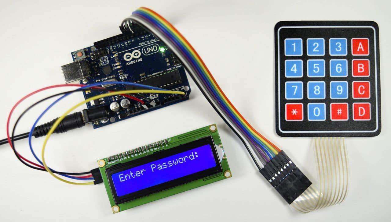
Keypads are a great way to let users interact with your project. You can use them to navigate menus, enter passwords, and control games and robots.
In this tutorial, I’ll show you how to setup a keypad on the Arduino. First I’ll explain how the Arduino detects key presses, then I’ll show you how to find the pinout of any keypad. As a simple example, I’ll show you how to print out the key presses on the serial monitor and an LCD. Finally, I’ll show you how to activate a 5V relay when a password is entered correctly.
I’ll be using a 4X4 matrix membrane keypad in this article, but there’s also code and wiring diagrams for 3X4 matrix keypads as well. I like membrane style keypads because they’re thin and they also have adhesive backing so you can stick them to most flat surfaces. You can also get telephone style keypads that have thicker buttons if you like that style better. Even salvaged keypads from old telephones will work with the Arduino.
How Keypads Work
The buttons on a keypad are arranged in rows and columns. A 3X4 keypad has 4 rows and 3 columns, and a 4X4 keypad has 4 rows and 4 columns:
Beneath each key is a membrane switch. Each switch in a row is connected to the other switches in the row by a conductive trace underneath the pad. Each switch in a column is connected the same way – one side of the switch is connected to all of the other switches in that column by a conductive trace. Each row and column is brought out to a single pin, for a total of 8 pins on a 4X4 keypad:
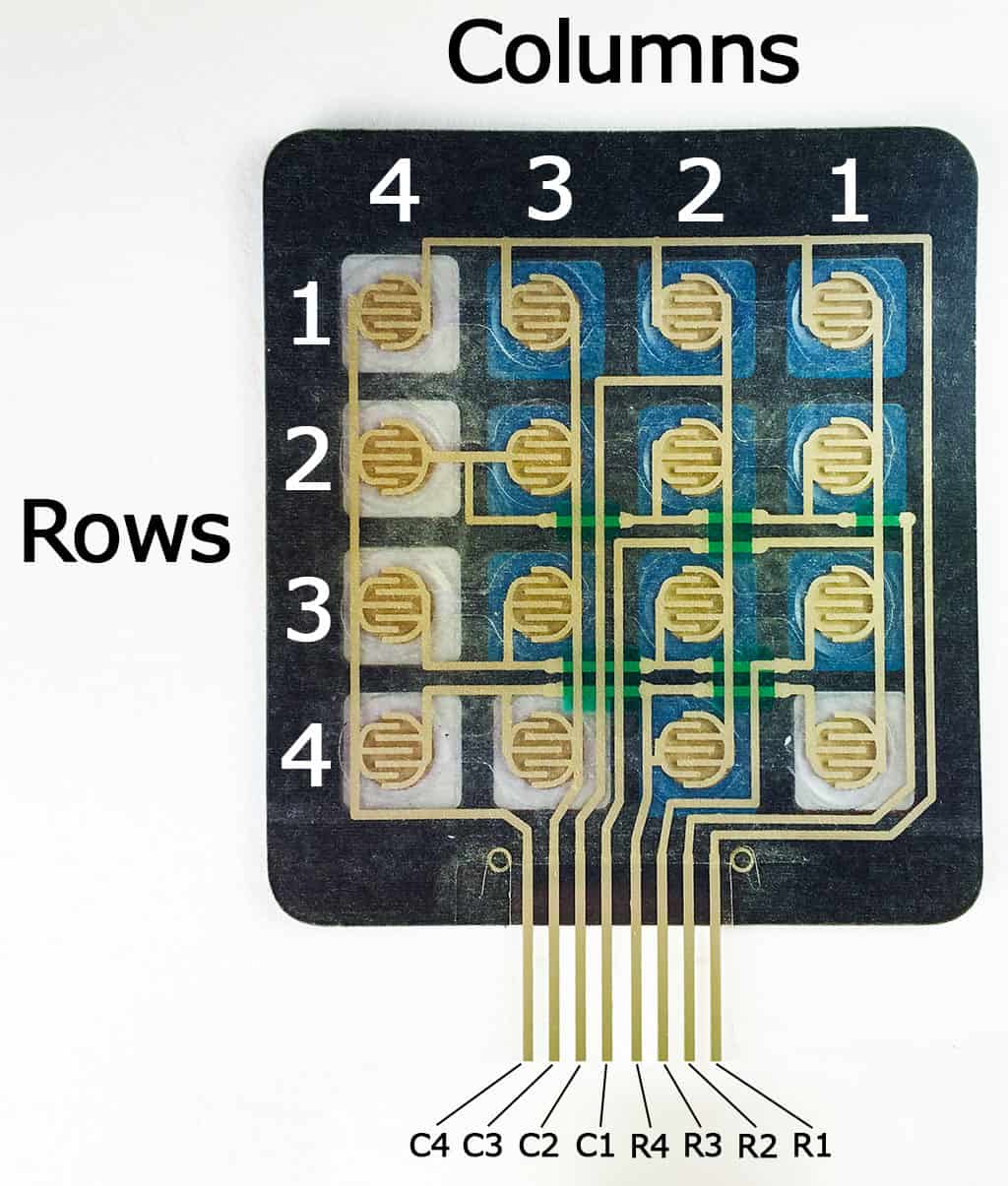
Pressing a button closes the switch between a column and a row trace, allowing current to flow between a column pin and a row pin.
The schematic for a 4X4 keypad shows how the rows and columns are connected:
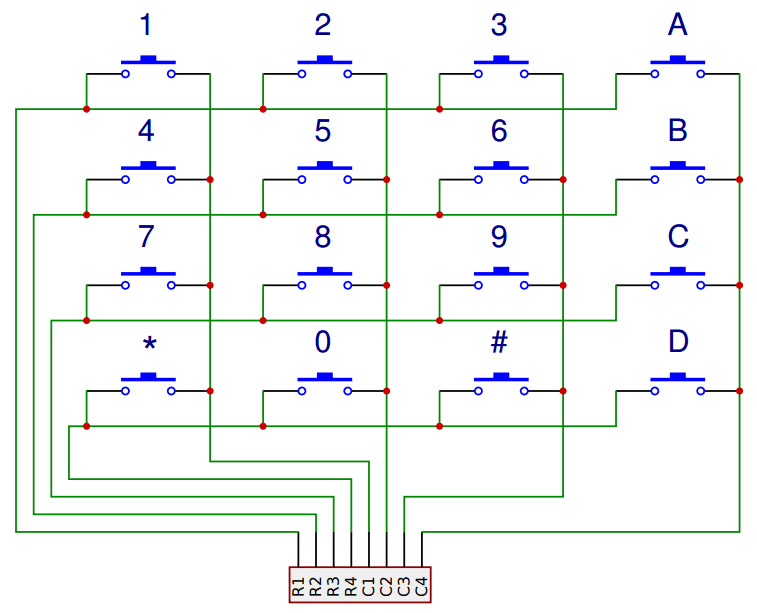
The Arduino detects which button is pressed by detecting the row and column pin that’s connected to the button.
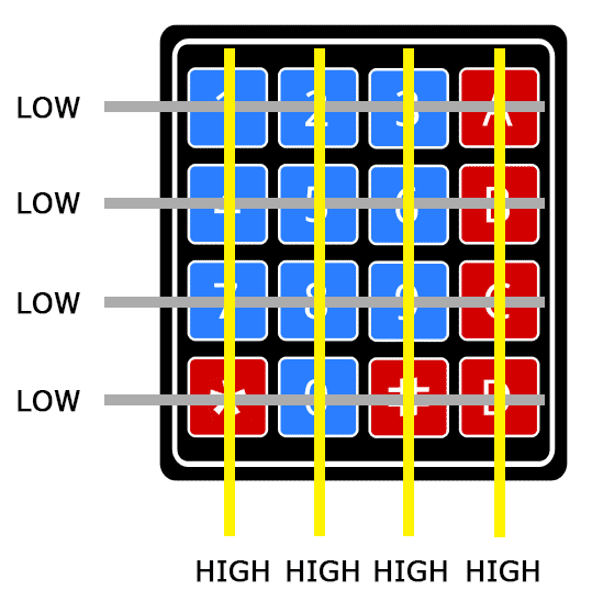
This happens in four steps:
1. First, when no buttons are pressed, all of the column pins are held HIGH, and all of the row pins are held LOW:
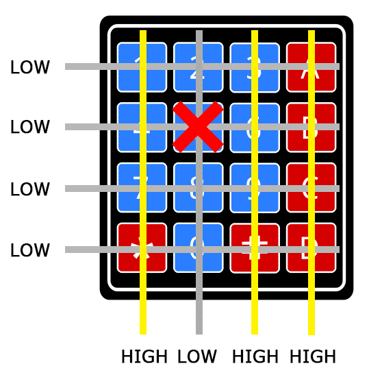
2. When a button is pressed, the column pin is pulled LOW since the current from the HIGH column flows to the LOW row pin:
3. The Arduino now knows which column the button is in, so now it just needs to find the row the button is in. It does this by switching each one of the row pins HIGH, and at the same time reading all of the column pins to detect which column pin returns to HIGH:
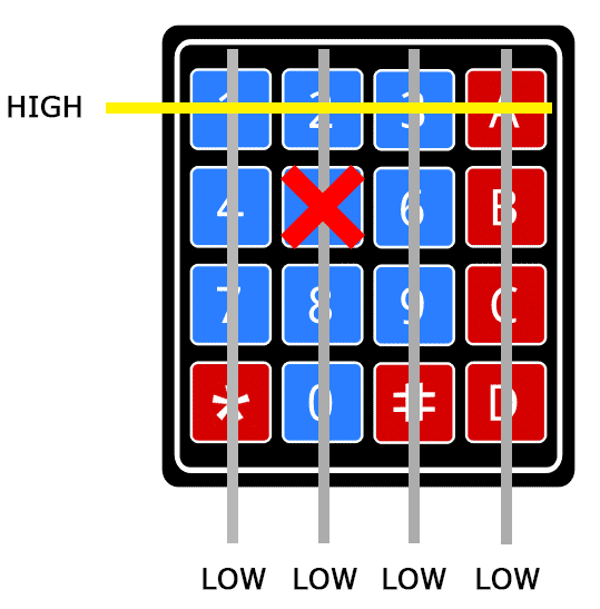
4. When the column pin goes HIGH again, the Arduino has found the row pin that is connected to the button:
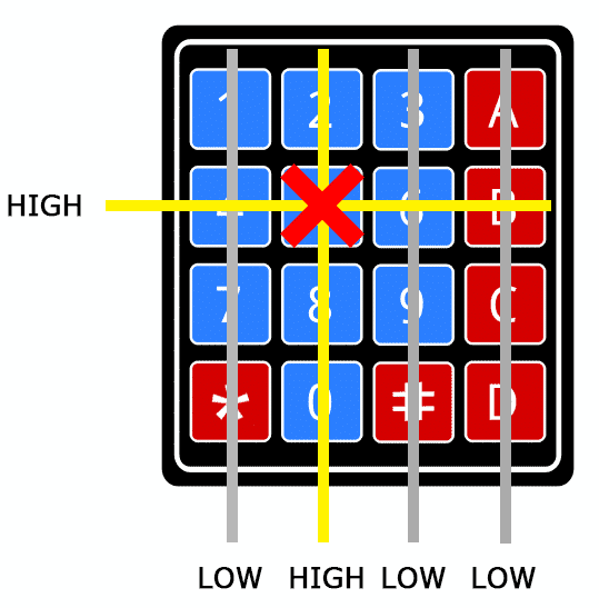
From the diagram above, you can see that the combination of row 2 and column 2 could only mean that the number 5 button was pressed.
Connect the Keypad to the Arduino
The pin layout for most membrane keypads will look like this:
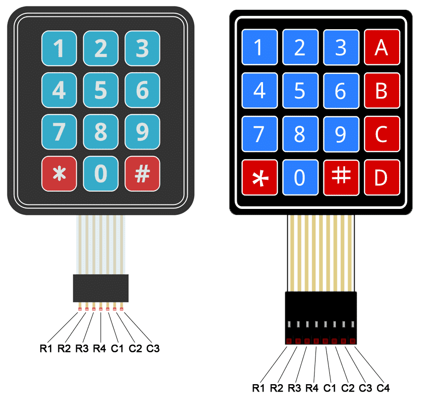
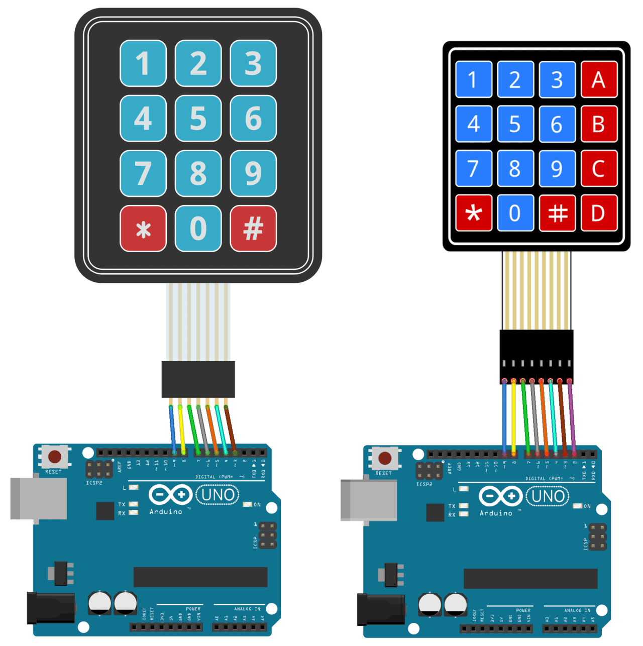
Follow the diagrams below to connect the keypad to an Arduino Uno, depending on whether you have a 3X4 or 4X4 keypad:
How to Find the Pinout of Your Keypad
If your keypad’s pin layout doesn’t match the ones above, you can probe the pins to figure it out. You’ll need to build a test circuit by connecting an LED and a current limiting resistor to the Arduino (or any 5V power source) like this:
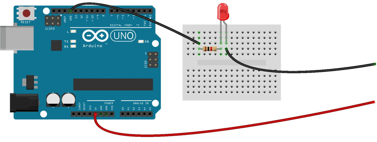
First, find out which keypad pins are connected to the button rows. Insert the ground (black) wire into the first pin on the left. Press any button in row 1 and hold it down. Now insert the positive (red) wire into each one of the other pins. If the LED lights up at one of the pins, press and hold another button in row 1, then insert the positive wire into each one of the other pins again. If the LED lights up on a different pin, it means the ground wire is inserted into the row 1 pin. If none of the buttons in row 1 make the LED light up, the ground wire is not connected to row 1. Now move the ground wire over to the next pin, press a button in a different row, and repeat the process above until you’ve found the pin for each row.
To figure out which pins the columns are connected to, insert the ground wire into the pin you know is row 1. Now press and hold any one of the buttons in that row. Now insert the positive wire into each one of the remaining pins. The pin that makes the LED light up is the pin that’s connected to that button’s column. Now press down another button in the same row, and insert the positive wire into each one of the other pins. Repeat this process for each one of the other columns until you have each one mapped out.
Programming the Keypad
For a basic demonstration of how to setup the keypad, I’ll show you how to print each key press to the serial monitor.
Install the Library
We’ll use the Keypad library by Mark Stanley and Alexander Brevig. This library takes care of setting up the pins and polling the different columns and rows. To install the Keypad library, go to Sketch > Include Library > Manage Libraries and search for “keypad”. Click on the library, then click install.
The Code for a 4X4 Keypad
Once the Keypad library is installed, you can upload this code to the Arduino if you’re using a 4X4 keypad:
The Code for a 3X4 Keypad
If you’re using a 3X4 keypad, you can use this code:
Lines 3 and 4 in the code above set the number of rows and columns on the keypad.
Lines 6-11 define which characters are printed when a particular button is pressed on the keypad. The characters are laid out just as they appear on the keypad. If your keypad has a different layout, you can define which characters are printed when you press a button. For example, say your keypad has a column of letters on the left instead of the right. You would just change it to this:
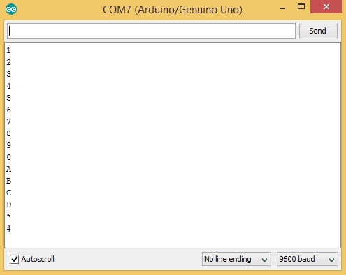
After you upload the code, open the serial monitor. When you press a key, the value will be printed out:
Using an LCD with the Keypad
Now let’s see how to print the key presses on an LCD. 4X4 keypads use 8 pins and 3X4 keypads use 7 pins. That takes up a lot of pins, so I’m going to use an I2C enabled LCD because it only needs 4 wires to connect to the Arduino.
Install the LiquidCrystal_I2C Library
To use an I2C enabled LCD on the Arduino, you’ll need to install the LiquidCrystal I2C library by Marco Schwartz. This library is nice because it includes most of the functions available in the standard LiquidCrystal library. To install it, download the ZIP file below, then go to Sketch > Include Library > Add .ZIP Library:
The Wire Library
The Wire library is needed to add support for I2C communication. It comes packaged with the Arduino IDE, so there’s no need to install it. But if for some reason it’s not installed on your system, go to Sketch > Include Library > Manage Libraries and search for “wire” to install it.
Connect the Keypad and LCD
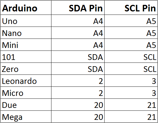
Once the libraries are installed, connect the ground and Vcc pins of the LCD to the Arduino, then connect the LCD’s SDA and SCL pins according to the table below for the different Arduino boards:
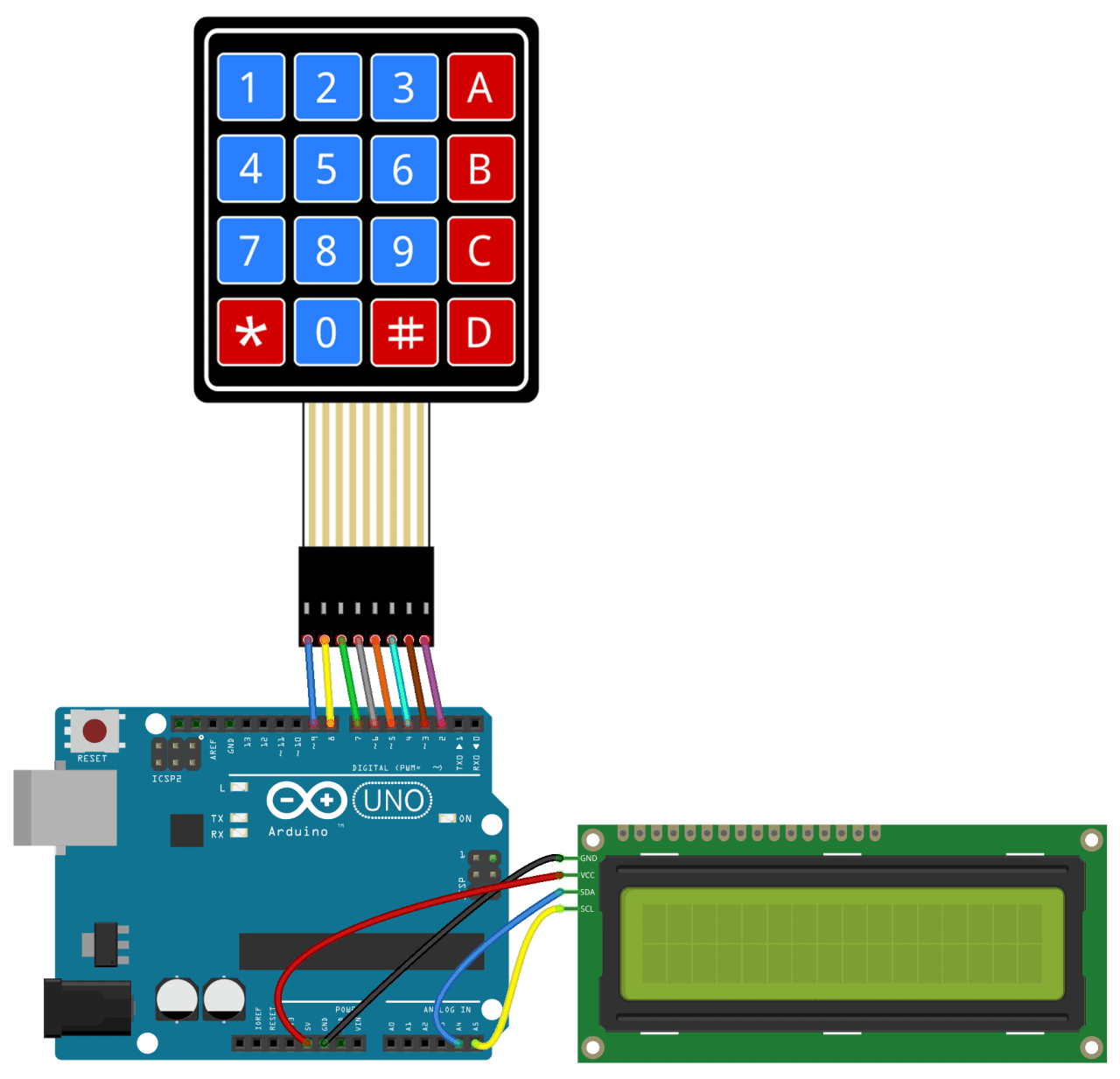
Then connect the keypad to the Arduino. It should look something like this (for an Arduino Uno):
Code for Output to an LCD
Once everything is connected, upload this code to the Arduino:
You’ll need to add the I2C address of your LCD on line 20:
LiquidCrystal_I2C lcd(0x21, 16, 2);
The I2C address of my LCD is 0x21, but your’s will probably be different. The I2C address of your LCD should be provided in the datasheet, but if not, you can find it by running this I2C_Scanner sketch.
Use a Password to Activate a Relay
One of the most useful applications of a keypad is to use it for keyed entry. You can set up a password and have the Arduino activate a relay or some other module if the password is correct. The following code will activate a 5V relay when the password is entered correctly:
You can change the password on line 10 by replacing the 123A456 text with your own password:
char Master[Password_Length] = «123A456»;
The length of the password needs to be set on line 5:
#define Password_Length 8
The password in the example above is only 7 characters long, but the password length is actually one greater than 7 because there is a null character added to the end of the string. For example, if your password is 5 characters long, you would enter 6 for the password length.
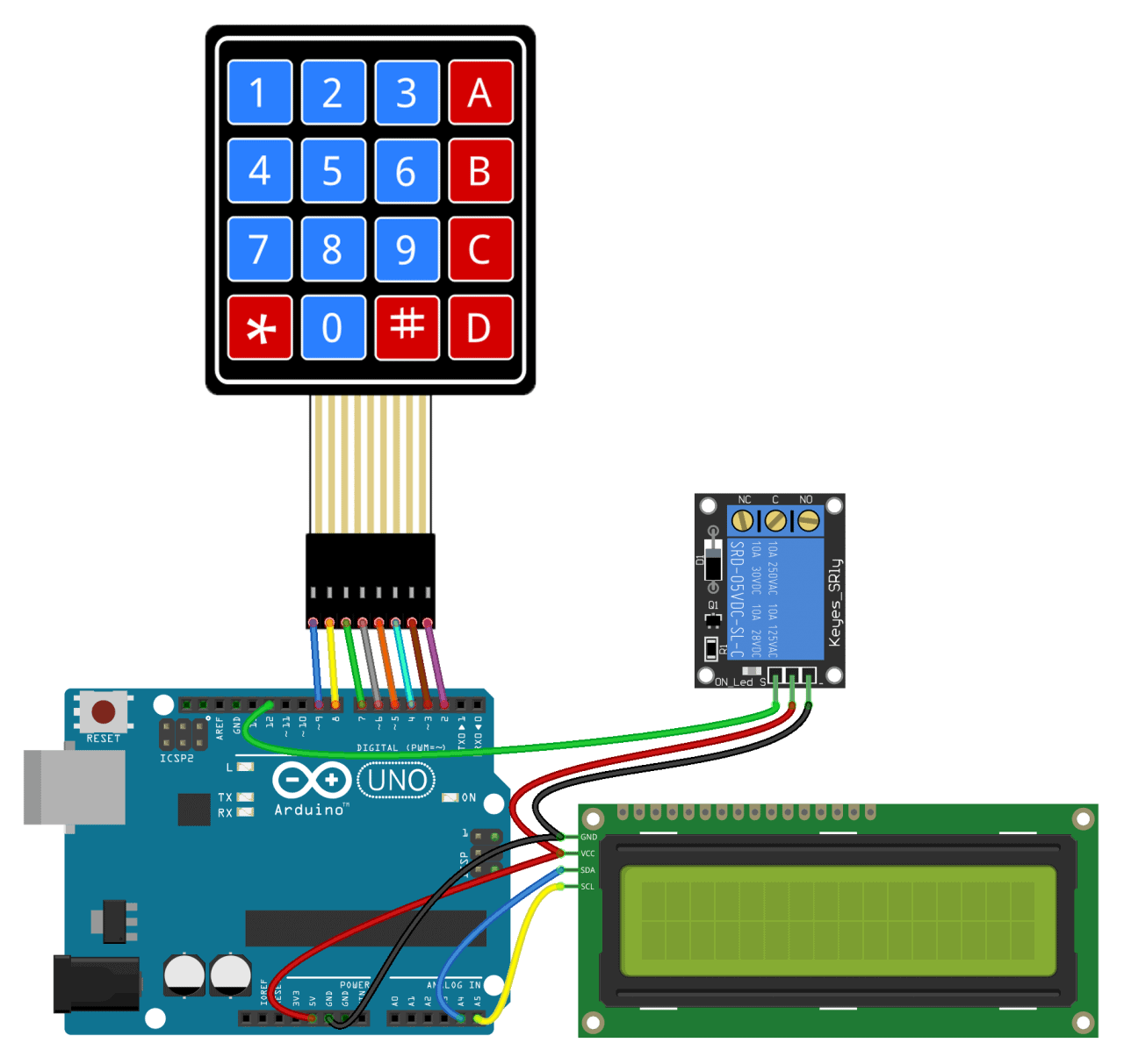
The output pin that activates the relay is defined on line 7:
int signalPin = 12;
After connecting everything to the Arduino, you should have something that looks like this:
Well that’s about it. It’s not hard to set up a keypad at all. I think with a little trial and error you should be able to modify the code above to work with most of the projects you’d want to use a keypad for. But if you run into problems, just let us know in the comments and we’ll try to help you out.