Interfacing 3.5 INCH TFT Display Shield with Arduino
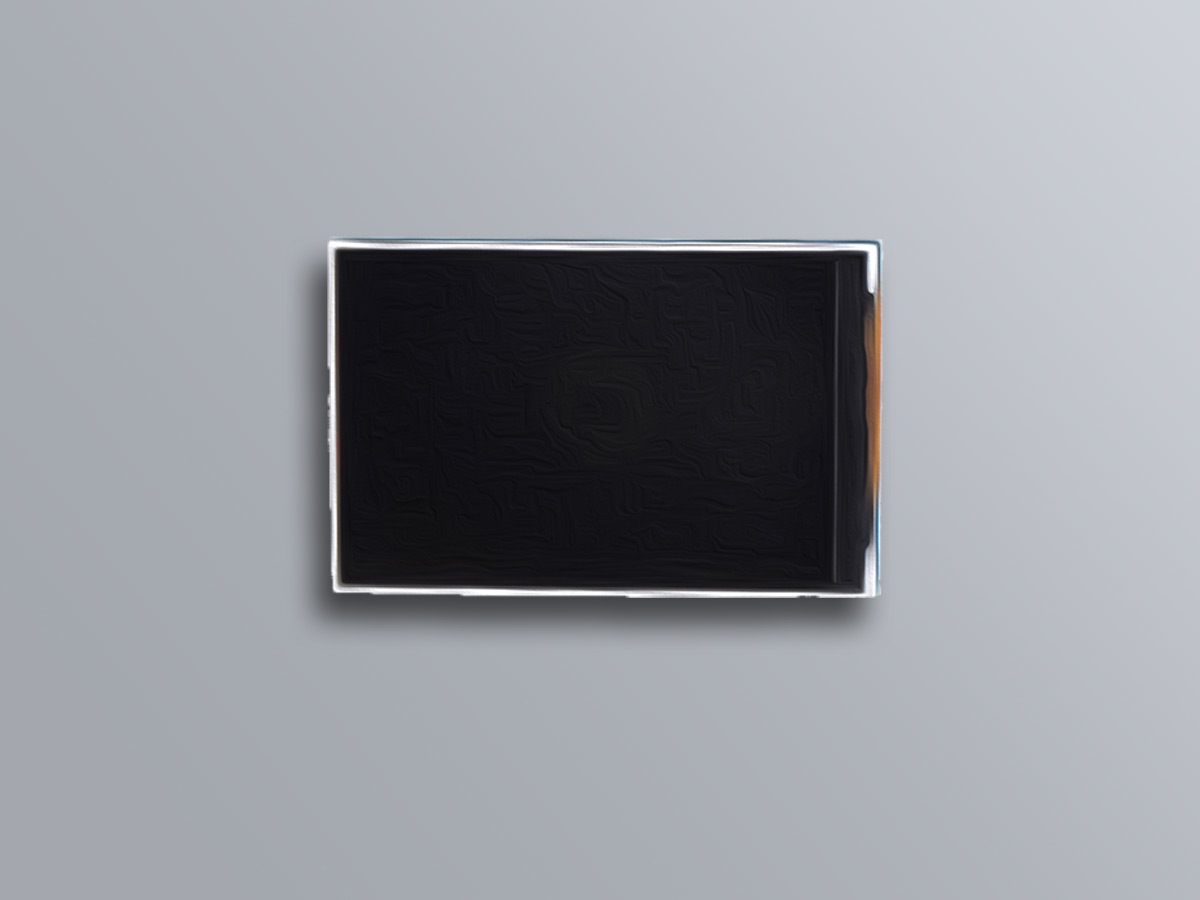
Table of Contents
3.5 INCH TFT DISPLAY Features
This module is a 3.5-inch TFT LCD module with “320X480” resolution and 65K color display. It is suitable for Arduino Uno and Mega2560 development boards, and also supports SD card expansion function. It uses 8-bit parallel port communication, and the driver IC is ILI9486.
You can download the datasheet of this module here.
3.5 INCH TFT DISPLAY Datasheet
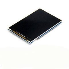
3.5 INCH TFT Display Pinout
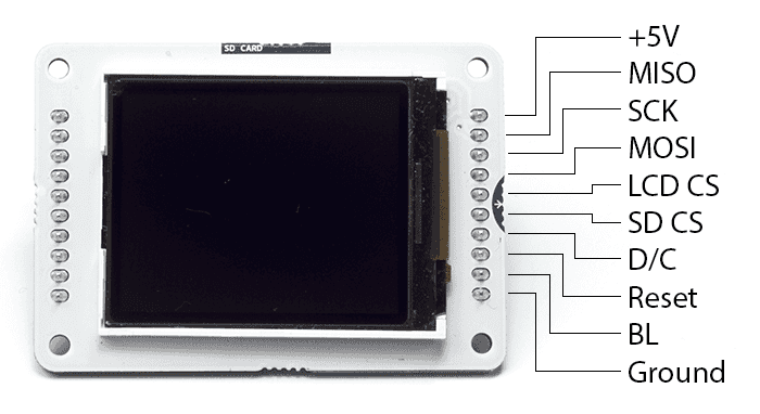
This module has 20 pins:
- 5V: Module power supply – 5 V
- 3.3V: Module power supply – 3.3 V
- GND: Ground
- LCD_RST: LCD bus reset signal, low level reset
- LCD_CS: LCD bus chip select signal, low level enable
- LCD_RS: LCD bus command / data selection signal, low level: command, high level: data
- LCD_WR: LCD bus write signal
- LCD_RD: LCD bus read signal
- LCD_D0: LCD 8-bit data Bit0
- LCD_D1: LCD 8-bit data Bit1
- LCD_D2: LCD 8-bit data Bit2
- LCD_D3: LCD 8-bit data Bit3
- LCD_D4: LCD 8-bit data Bit4
- LCD_D5: LCD 8-bit data Bit5
- LCD_D6: LCD 8-bit data Bit6
- LCD_D7: LCD 8-bit data Bit7
- SD_SS: SD card SPI bus chip select signal, low level enable
- SD_DI: SD card SPI bus MOSI signal
- SD_DO: SD card SPI bus MOSI signal
- SD_SCK: SD card SPI bus clock signal
You can see the pinout of this module in the image below.

Required Materials
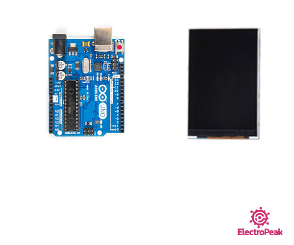
Hardware Components
| Arduino UNO R3 | × | 1 |
| 3.5 inch Touch TFT LCD Display Shield | × | 1 |
Software Apps
Interfacing 2.4 INCH TFT Display with Arduino
Step 1: Circuit
The 3.5-inch display is a ready-made shield for Arduino Uno, which can also be placed on the Arduino Mega. The pins of this shield are designed to be easily installed on the Arduino. The bad point about these modules is that they use all Arduino Uno pins.
Step 2: Code
First, download the following code.
Now open it and follow the path below.
- Demo\Demo_Arduino\Install libraries
Copy the LCDWIKI_KBV folder to your Arduino library.
Then enter the folder and follow the path below.
- 2. Example\Example_02_colligate_test\colligate_test
Run the Arduino file in the folder and look for the following line.
Then uncomment it and upload the code to your Arduino.
This code is for testing display and shows various shapes and designs graphically.
Getting Started with the Arduino TFT Screen
This is a retired product.
The Arduino TFT screen is a backlit TFT LCD screen with a micro SD card slot in the back. You can draw text, images, and shapes to the screen with the TFT library.
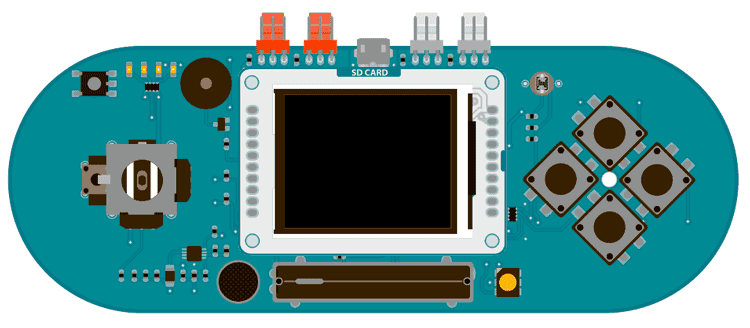
The screen’s pin layout is designed to easily fit into the socket of an Arduino Esplora and Arduino Robot, but it can be used with any Arduino board.
Library
The Arduino TFT library extends the Adafruit GFX, and Adafruit ST7735 libraries that it is based on. The GFX library is responsible for the drawing routines, while the ST7735 library is specific to the screen on the Arduino screen. The Arduino specific additions were designed to work as similarly to the Processing API as possible.
The library is backwards compatible, which means you can still use the Adafruit functions described here.
The TFT library relies on the SPI library, which must be included in any sketch that uses the scree. If you wish to use the SD card, you need to include the SD library as well.
Screen layout
By default, the screen is oriented so it is wider than it is tall. The top of the screen is the same side as the text ‘SD CARD». In this orientation, the screen is 160 pixels wide and 128 pixels high.
When thinking about coordinates on the screen, imagine a grid. Each square in the grid is a pixel. You can identify the placement of pixels with specific coordinates. A dot in the top left corner would have coordinates of 0,0. If this dot were to move to the top right of the screen, its coordinates would be 0, 159; in the bottom left corner, the coordinates would be 127,0, and in the bottom right it would be 127,159.
It is possible to use the screen in a vertical, (also called «portrait») orientation, by calling setRotation(0) . When you call this, the x and y-axes change accordingly, and calls to screen.width() or screen.height() change as well.
Colors
The screen has the ability to show 16-bit color. The red and blue have 5-bits of resolution each (32 levels of red and blue), the green has 6-bits of resolution (64 different levels). For consistency with other applications, the library deals with color in 8-bit values for the red, green, and blue channels (0-255), and scales the colors appropriately.
Hardware vs software SPI interface
The screen can be configured for use in two ways. One is to use an Arduino’s hardware SPI interface. The other is to declare all the pins manually. There is no difference in the functionality of the screen between the two methods, but using hardware SPI is significantly faster when drawing.
If you plan on using the SD card on the TFT module, you must use hardware SPI.
All the examples are written for hardware SPI use.
Connecting the screen
Connecting to the Esplora
There is a socket on the front of the Esplora for the screen. Insert the screen into the socket with the blue tab that says «SD Card» closest to the USB port.
Connecting to other Arduino boards
To connect the screen to other Arduino boards, read the tutorial on this link.
Write your first program
To get started with the screen, first write a program that will draw a line, then 2 rectangles horizontally across the screen in different colors.
The first set of instructions are for the Uno, Leonardo, and similar boards. For use with the Esplora, see below.
First, declare the pins to use, import the necessary libraries, and instantiate a named instance of the TFT library. :
In setup() , you need to start the library with begin() and clear the screen by filling it in black with background() .
in loop() , to draw a line across the screen, call line() . line() takes four arguments, the the starting x and y coordinates, and the ending x and y coordinates. For drawing a box, use rect() . rect() take four arguments as well : the x and y coordinates of the top left corner, followed by the width in pixels, and the height in pixels. Between each of these calls, change the color with stroke() or fill() . stroke() will change the color of a line, or the outline around a shape. fill() changes the internal color of a shape. Calling noStroke() will stop the library from drawing an outline around any shapes that follow it. If you call stroke() after noStroke() , the screen will again draw lines.
If you are using an Esplora, the structure of the program is the exact same. As the Esplora has a socket designed for the screen, and the pins for using the screen are fixed, an Esplora only object is created when targeting sketches for that board. You can reference the screen attached to an Esplora through EsploraTFT .
You do not need to declare any pins in your sketch; the object is instantiated for you automatically :
Movement across the screen
To give the illusion of motion, you need to quickly erase and draw images on the screen. When using Processing on a powerful computer, you can call background() every time through your draw() function to erase the window contests and dra objects in their new positions. The Arduino is not as fast, is it takes a little time to clear the screen when calling background() with the TFT library.
To create the illusion of motion, it’s usually best to check if an object has moved each time through loop() . If it has, then you should draw over the object with your background color, then redraw the object in its new location. Because you’re not updating all the pixels on the screen, it helps maintain the illusion of motion.
This example draws a single point, and has it bounce around on the screen. You’ll set up the program in the same way you did previously, adding some variables to keep track of the point’s current and previous locations, as well as the velocity and direction of the point.
In @@loop()@ you’ll first update the position of the dot by adding the direction to the x and y position variables. After that, check to see if there is a difference between the current and the previous locations of the point. If there is a difference, erase the previous location by filling in the dot the same color as the background, then drawing a new dot in the updated location. If the point happens to run into the boundaries of the screen, have it reverse direction.
The Esplora version is below :
Draw some text
The TFT library includes a basic font for drawing text on screen. By default, characters are 5 pixels wide and 8 pixels tall. It is possible to change the font size to 10×16, 15×24, or 20×32. For additional information on the underlying font capabilities, see the Adafruit page on graphic primitives.
In this example, you’ll create a basic counter that will update a number on screen every half second. As in the earlier examples, include the necessary libraries and variables before setup() .
In setup() send the static text that won’t change to the screen. With setTextSize() you can increase the font size to make important parts stand out. Dynamic text for the screen should be stored in a char array. The String class makes it easy to update the text over time in the array.
In loop() , you’ll get the current time, and store the number in a char array. Before each loop ends, erase the text you wrote earlier so it doesn’t overwrite itself.
The Esplora code :
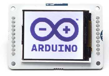
Draw an image from the SD card
The TFT library has the ability to read .bmp files off a SD card and display them on the screen. Images can be smaller or larger than the screen resolution (160×128), but there is no method on the Arduino for image manipulation. The images should be sized before you put them on the SD card.
In the following example, a bitmap that is 160×128 pixels named «arduino.bmp» is in the root directory of a SD card. When read by the library and drawn, the image will fill the screen.
In addition to the libraries you have been including to this point, you will also need to include the SD library. You’ll also need to declare a CS pin for the SD slot.
The PImage class is used to load the image and can also check if the image is a valid file that the library can read.
Once read, the image will be rendered from the coordinates you decide. In this case, it starts drawing from the top left of the screen.
For the Esplora :
Next steps
Now that you have tested the basic functionality of the screen, see the TFT library pages for information about the library’s API and additional examples. See the hardware page for more information about the screen’s components. It’s also recommended to visit the Adafruit graphics library page for additional information on functions not covered.
The text of the Arduino getting started guide is licensed under a Creative Commons Attribution-ShareAlike 3.0 License. Code samples in the guide are released into the public domain.
Дисплей Nextion HMI. Работа с китайской версией TJC
Как уже известно из предыдущих уроков, к Ардуино можно подключить множество разных дисплеев. Для самых простых проектов пригодится символьный ЖК дисплей 1602, который мы уже изучили на одном из уроков. Для вывода простейшей монохромной графики можно использовать дисплей от телефона Nokia 5110, либо более современный OLED дисплей. Ресурсов Ардуино хватает даже на цветные дисплеи с TFT матрицей.
Однако, чем сложнее дисплей, тем тяжелее приходится нашей Ардуино. Несмотря на самые изощренные и быстрые библиотеки, ресурсов микроконтроллера Atmega328 едва хватает для работы с цветной TFT матрицей. Для полезного кода остается менее половины флеш-памяти контроллера. Что делать в такой ситуации?
Технология HMI
Выход есть. Собственно, первое что приходит на ум — это наделить графический дисплей собственным микроконтроллером, который бы выделил весь свой вычислительный ресурс на обработку графики. Такой готовый модуль можно бы было подключать к Ардуино по одному из стандартных интерфейсов, и обмениваться с ним унифицированным командами.
Именно такой модуль мы и разберем на этом уроке. Называется этот графический модуль — Nextion HMI. Сокращение HMI означает Человеко-Машинный Интерфейс. Разработчики этого модуля предполагают, что именно такие устройства будут использоваться в элементах «умного дома», и разного рода гаджетах.
Существуют версии Nextion с различной диагональю, а также с версии с тачскрином. В нашем уроке мы используем самый простой дисплей с диагональю 2.2 дюйма и разрешением 320×240, без тачскрина.
Создание интерфейса
Как уже было сказано, дисплей Nextion имеет свой собственный контроллер, который отвечает за отрисовку графики. Чтобы этому контроллеру было что рисовать, мы должны заранее создать графические образы, связать их с командами, и загрузить всё это в память дисплея. Для этих целей мы воспользуемся специальным редактором интерфейсов, который был разработан командой Nextion. Скачать редактор можно на официальном сайте.
Для русификации редактора следует заменить файл cs.lang в папке с редактором. Переведенный файл можно взять тут:
http://git.robotclass.ru/download/NextionEditor
Наша задача будет состоять в том, чтобы сделать графический интерфейс для отображения показаний акселерометра. Соответственно, нам понадобится создать какой-то красивый фон, разместить на нем поля для вывода чисел. Также хотелось бы добавить и какие-нибудь компоненты для визуализации показаний, например шкальные индикаторы.
Итак, запускаем редактор. Перед нами появляется главная форма.

1) Первое что мы сделаем — создадим новый проект. Жмем меню «Файл/Новый», выбираем папку где будет храниться файл проекта и его имя, например, test.hmi. Затем выбираем в появившемся окне подходящий формат и ориентацию дисплея.

2) Теперь добавим фон нашего интерфейса. Жмем кнопку «Добав.» (Add) в разделе Изображения.

В появившемся окне выбираем файл картинки с разрешением 320×240. Для урока мы нарисовали свой фон, в виде трех оранжевых прямоугольных областей.
3) Добавляем в интерфейс компонент «Изображение».

По-умолчанию, компонент размещается в левом верхнем углу. Не будем его никуда двигать, и перейдем к настройкам компонента.
4) Ассоциируем компонент и ранее добавленную картинку. Для этого, в разделе настроек компонента жмем на параметр pic, и выбираем единственную в списке картинку.

5) Аналогичным образом, добавляем компонент «Индикатор выполнения». Обычно этот блок служит для отображения статуса загрузки данных, но мы используем его для визуализации показаний с нашего датчика.

Параметры bco и pco задают цвет фона элемента и цвет, которым заполняется индикатор. В нашем случае фон белый, и сам индикатор синий. Параметр val определяет степень наполнения индикатора, и варьируется от 0 до 100. Именно этот параметр мы и будем менять с помощью Arduino. Кстати, можно менять любой параметр, отмеченный зеленым цветом.
Остальные параметры отвечают за положение элемента на дисплее: x и y, а также за его размеры: w и h.
6) Добавляем на дисплей еще два таких же индикатора и настраиваем их. Затем добавляем компонент «стрелка» (gauge).

Стрелка — это что-то вроде стрелки на спидометре автомобиля. Имеет диапазон значений от 0 до 360. Размещаем её в верхней правой части дисплея. Чтобы у стрелки был красивый круглый фон (можно и циферблат нарисовать), мы переключим параметр sta в режим crop image. Потребуется заполнить параметр picc; укажем там ту же картинку, что и для фона. Crop image означает, что фон компонента станет прозрачным, и через него будет просвечивать указанная в параметре picc картинка.
7) Перед тем, как добавить числовые поля, создадим шрифт. У дисплея нет такого же хранилища шрифтов, как в MS Windows, и он не умеет пользоваться стандартными файлами ttf. Чтобы добавить шрифт, нажмем кнопку «Добав.» (Add) в блоке «Шрифты», который находится в левой части редактора.

Задаем высоту шрифта, жирность. Указываем имя шрифта. При изменении каждого параметра, в маленьком черном квадратике будет меняться написание буквы X. Не очень удобная настройка, но что поделать. Наконец, в поле «Имя шрифта» записываем подходящее название латинскими буквами и жмем «Создать шрифт». Генератор пробежится по всем буквам векторного шрифта, и создаст их растровые изображения, который мы потом загрузим в память дисплея вместе с графикой.

8) Добавляем на форму три компонента «Число».

В настройках компонента указываем номер шрифта font. У нас создан пока только один шрифт, так что его номер будет — 0. Параметр val отвечает за содержимое поля, его мы будем задавать через Arduino. В примере мы так же поменяли цвет и фон компонента.
9) Последний компонент, который мы разместим на нашем дисплее — «Текст». Мы не будем менять его содержимое, просто что-нибудь напишем в параметре text.
10) Наконец, скомпилируем все что мы сделали в файл, который затем отправится в память дисплея. Жмем кнопку «Компилировать» (Compile).

Файл имеет расширение tft и хранится в папке, которую можно открыть через меню «Файл/Открыть папку с tft файлами».
С интерфейсом всё, переходим к самой ответственной части.
Nextion и TJC
Nextion HMI — марка дисплея для европейского рынка. В Китае существует версия для внутреннего рынка, которая носит название TJC (по названию чипа). С точки зрения электроники, они полностью идентичны. Как это обычно бывает, версия для Европы стоит значительно дороже. Подвох тут в том, что европейский редактор не позволяет загружать прошивку в китайский дисплей. Делать же интерфейс в китайском редакторе, немного неудобно.
Чтобы решить эту проблему, энтузиасты разработали различные варианты программ, которые позволяют загружать любую прошивку в любой дисплей, будь то Nextion или TJC. Одной такой программой, которую мы немного модернизировали, мы и воспользуемся.
Загрузка файла интерфейса
2) Чтобы его запустить, потребуется установить интерпретатор Python 2.7.
3) После установки python, установим библиотеку для работы с последовательным портом — pyserial.
4) Скрипт имеет несколько важных параметров, которые хранятся в отдельном файле config.py:
Последовательный порт, через который будет происходить загрузка. Меняем на актуальный:
PORT = ‘COM6’
Загрузка прошивки идет в два этапа, с разной скоростью. Обычно эти параметры менять не следует.
BAUDCOMM = 9600
BAUDUPLOAD = 115200
Идентификатор дисплея, который указан либо на самом дисплее, либо на коробке. В уроке мы использовали TJC3224T022.
CHECK_MODEL = ‘TJC3224T022’
Наконец, параметр определяющий временную задержку в протоколе обмена. Этот параметр нужно будет изменить только если процедура загрузки не удастся.
BAUDRATE_SWITCH_TIMEOUT = 0.5
5) Загружать прошивку будем через USB-UART мост, например такой:

Схема соединения моста и дисплея:
| Nextion/TJC | GND | VCC | RX | TX |
| USB-UART | GND | +5V | TX0 | RX1 |
6) Скопируем скомпилированный файл интерфейса tft в папку со скриптом, и запустим скрипт через командную строку:
7) После запуска скрипта на дисплее запустится процедура загрузки с индикатором хода выполнения. Если всё пошло как надо, то дисплей напишет об успешном выполнении процедуры и перезагрузится. Python-скрипт тоже отчитается о проделанной работе:

Если загрузка остановилась на 0%
Если загрузка зависла на 0%, значит следует изменить тот самый временной параметр в настройках. Рекомендую присвоить ему значение 0.05.
Также предстоит починить прошивку дисплея, иначе он не даст повторить процедуру. Для этого понадобится microSD карта. Загружаем на карту подходящую прошивку из папки со скриптом «TJCUpload/Basic Recovery». Эта прошивка минимальная, и служит лишь для ремонта. Вставляем флешку в дисплей, подаем питание. Ждем несколько секунд, пока прошивка не загрузится автоматически.
После этой процедуры можно повторить загрузку подготовленной ранее прошивки, не забыв изменить указанный параметр в файле настроек скрипта.
Программа
Приступим к написанию программы для управления HMI дисплеем. Каждый компонент имеет свой идентификатор. Индикаторы выполнения, размещенные на форме: j0, j1 и j2. Числовые поля: n0, n1 и n2. Компонент «стрелка» получил идентификатор z0.
Чтобы изменить параметр val у компонента, нам нужно передать в последовательный порт команду вида:
Каждая команда должна завершаться тремя байтами 0xFF. Тестовая программа будет менять значение индикатора j0 в цикле.
Загружаем программу на Ардуино, и подключаем дисплей по схеме:
| Nextion/TJC | GND | VCC | RX | TX |
| Ардуино Уно | GND | +5V | 1 | 0 |
Подаем питание на Ардуино и наблюдаем движение самого верхнего индикатора.
Визуализация показаний акселерометра
Теперь добавим в скетч управление всеми остальными компонентами.
Загружаем скетч на дисплей, и крутим акселерометр вокруг осей.

Ну и небольшое видео, если у вас не грузится анимированный gif:
Заключение
На этом уроке мы разобрали работу Nextion/TJC дисплея с разрешением 320×240 без тачскрина — это самый простой вариант из линейки. Разумеется, гораздо интереснее будет поработать с компонентами, отвечающими за реакцию тачскрина. На следующем уроке мы изучим именно такой продвинутый вариант дисплея, и попробуем поработать со слайдбарами и кнопками. Также построим график с помощью специального компонента, разберемся с таймером и переменными. Успехов!