Make a Fan Controller with Arduino © CC BY-NC-SA
You have a fan, but you don’t know how to control it? Then you’re right here.
 |
| × | 1 | ||
 |
| × | 1 | ||
| × | 1 |
I have a server of two Raspberry Pis and they needed to be cooled. I grabbed a fan. But it was way to loud! So I got an Arduino, wrote some Code and now I can control my fan.
Step 1: Figure out the pins of the fan connector
You need a fan with a Plus (red) pin, a Minus (black) pin and a Speed pin. Some fans with three pins have plus, minus but then a Speedometer pin. The Speedometer pin is an output of the fan saying how fast the fan is rotating. Fans with four pins have a Speedometer pin and a Speed pin.
Step 2: Connect the Arduino to the fan
Connect 12V to the Plus pin of the fan, GND to the Minus pin of the fan and a PWM pin, for example pin 3 of the Arduino to the Speed pin of the fan.
Step 4: Control it!
You can change the fan speed with putting in a number over serial. It saves the number also in the EEPROM (at FS_ADDR) so when it resets, the speed will be the same than before.
How to properly control PWM fans with Arduino
Introduction
Computers have been using PWM-controlled fans for ages now (they’re the ones with a 4 pin connector). This allows the BIOS to change the fan speed according to the current temperatures using a PWM signal instead of changing the voltage of the fan, which means that motherboards are cheaper to make (less voltage regulators), but also that fans are much easier to control, since DC motors won’t even move below a certain voltage threshold.
The exact specs of these fans were made by Intel in the mid-00s and are available here: Original | Latest version | Noctua
Connecting the fan to the Arduino
We can connect up to 3 PWM fans to a single Arduino.
This is the pinout of a standard PWM fan: 
- Black: Ground
- Yellow: +5V, +12V or +24V (depends on fan model, usually 12V for desktops, 5V for laptops)
- Green: Sense. Used to measure RPM
- Blue: PWM control signal at 5V, 25kHz
Notice the presence of a notch on the connector: this is to ensure that you don’t connect it backwards, and also to ensure compatibility with older 3 pin connectors. Polarity protection is a requirement of the spec so even if you force it, you won’t damage the motherboard or the fan.
If you have a 12V fan, the best way to power it is to put the Arduino and the fan in parallel, using the VIN pin to power the Arduino. It’s a good idea to put a diode in front of the VIN pin if you have it, that way you can connect both the 12V and the USB without damaging anything.
If you have a 5V fan, you can power it directly from the 5V pin on the Arduino, but I don’t recommend it if it draws more than 4-500 mA, as it could damage the voltage regulator on the Arduino, and also generate noise that could cause the Arduino to be unstable. If unsure, power the Arduino and the fan in parallel with a 5V supply connected to both the fan and the 5V pin.
If you have a 24V fan, you’ll have to power both the fan and the Arduino externally. Note that the Arduino can only take up to 12V as input in the VIN pin, and the Arduino and the fan MUST share the same ground!
Note: if you’re using really shitty fans, you should add a flyback diode between the ground and power pins of each fan.
Important: the VIN pin on the Arduino has no polarity protection, double check your connections before turning it on!
Example schematic for a single 12V fan: 
PWM control
This is the tricky part. The specs require a PWM signal with a frequency of 25 kHz (with tolerance, 21-28 kHz), but our usual analogWrite function doesn’t output anywhere near that frequency. By using some timer tricks, we can make it generate 3 PWM signals at the correct frequency. I’ll show you the code first and then explain it.
Explanation
The PWM signals on the Arduino Uno (and others based on the ATmega328p, such as the Nano) are generated by 3 internal timers. With the default settings and using analogWrite with a value of 127, this is what we see on an oscilloscope: 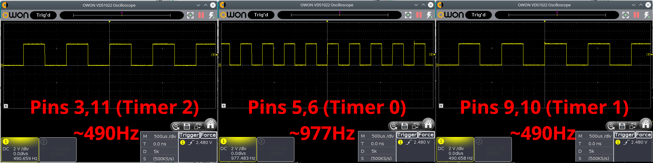
As you can see it’s nowhere near the required frequency. You can run a fan with this signal but it will behave erratically.
- Timer 1 (Pins 9,10) is a high resolution 16 bit timer. This is used by libraries like Servo. We want to take the clock as it is (no prescale) and feed it to the counter; we use mode 10, which counts up to the value of register ICR1, which we set to 320 instead of 65535, giving us a period of roughly 25 kHz. OCR1A and OCR1B control the duty cycle of our output PWM on pins 9 and 10 respectively, independently. We have 320 possible values for the duty cycle with this timer.
- Timer 2 (Pins 3,11) is a low resolution 8 bit timer. This is used by many libraries and functions such as tone. This timer doesn’t have an ICR register like Timer 1, so instead we divide the clock by 8 (prescale 8) and feed it to the counter; we use mode 5 and set output A to trigger a reset of the counter when it reaches 79 instead of 255, resulting in a period of roughly 25 kHz. OCR2B controls the duty cycle of our output PWM on pin 3. Pin 11 is unusable for output because of this mode. We only have 79 possible values for the duty cycle with this timer.
- Timer 0 (Pins 5,6) is identical to Timer 2, so we could apply the same settings that we used for it and get an extra output for a fourth fan; however, it is used for all timing functions such as delay, millis, etc. and touching it would cause everything that depends on this to behave erratically, including our Serial output. My code doesn’t touch this timer.
This is the PWM output on the 3 channels generated by the example code: 
As you can see in the bottom left corner, the oscilloscope detects a 25 kHz signal on all outputs.
Apart from having to remember not to use functions and libraries that use Timers 1 and 2, there are no real drawbacks from using this code. The signal looks a bit less clean, but that’s because the frequency is over 50 times higher.
Note that the official spec says that the minimum duty cycle for the fans should be 20%. Decent fans like the Noctua ones I used in my tests can take any duty cycle, but you should keep it in mind if you’re using cheaper fans.
RPM detection
The rotation sensor on the fan can interface with the Arduino. It expects to be connected with a pullup resistor and it generates 2 impulses per rotation.
The best way to read this is to use one of the Arduino pins that can do interrupts (2 and 3 on the Arduino Uno). I will use pin 2 in this example:
License
You are free to do what you want with the code on this page.
Project based on this code
I made a simple fan controller to put in a computer case, powered directly from one of the fan headers on the motherboard. This controls up to 3 fans to keep the temperature inside the case in check.
lefth/fan-speed-control
Use Git or checkout with SVN using the web URL.
Work fast with our official CLI. Learn more.
Launching GitHub Desktop
If nothing happens, download GitHub Desktop and try again.
Launching GitHub Desktop
If nothing happens, download GitHub Desktop and try again.
Launching Xcode
If nothing happens, download Xcode and try again.
Launching Visual Studio Code
Your codespace will open once ready.
There was a problem preparing your codespace, please try again.
Latest commit
Git stats
Files
Failed to load latest commit information.
README.md
Arduino speed control for a four-wire desktop computer fan. Good for magnetic stirrers.
Four-wire computer fans have speed controlled by PWM applied to one of the wires. The wire is normally pulled up to 5-12 V, and to reduce the fan speed, we should pull it down. Pulling it down all the time would tell the fan to turn at its lowest speed. Leaving it high lets the fan run at max speed. If we use PWM to pull it down some of the time, the duty cycle will determine the fan’s speed. Note that you must use a transistor to pull the connection down, as the voltage sometimes goes much higher than an Anduino port can handle.
The fan may not be able to handle very high frequency PWM, so Arduino is advantageous over a faster dedicated PWM controller.
My circuit has the optional feature of using a momentary push button to change whether the fan is on. Connect one end of the button to Arduino and the other end to ground, so the button press pulls the pin down. If you don’t need this, you can hook the fan up to a 12 V power supply directly.
I am using a 10 k potentiometer (as a voltage divider) to control the speed. Measure voltage from the pot’s middle pin. If you want to use some other logic to determine the desired speed, rewrite the getChosenSpeed function.
My circuit uses two 2222A transistors, but you could use almost any transistor.
Why not use a 555 timer?
Since Arduino is popular with beginners, there are a lot of people that don’t have a 555 timer. If you have it and know how to use it, use the 555! You may need to limit the frequency so it doesn’t get so high the fan gets confused.
Use for magnetic stirrers
Magnetic stirrers are very easy to make with a computer fan, but people typically control their speed by limiting the voltage with a variable resistor. This works badly because they may not have enough torque to get started until they’re at nearly full power. (And good luck trying to stir a thick liquid.) Using the built in speed control doesn’t have that problem. However, operation is still limited by the lowest speed. My fan’s minimum speed is probably still too fast to stir something very thick like honey.

More info about 4-wire fans
I learned about the speed control in this video: https://www.youtube.com/watch?v=gKHww3qJbs8
About
Arduino speed control for a four-wire desktop computer fan. Good for magnetic stirrers.
Arduino fan controller
There are many different ways to control the speed of a fan. For example, if your fan has a PWM wire, then you could directly use the PWM signal. Also see our other post for an Arduino fan controller with a Bluetooth Android app.
In this post we show you how to regulate the rotational speed of any fan. It doesn’t matter if your fan needs 12 Volt or 5 Volt. Also the number of wires is not important. You can use a 3, 4 or 2 wire fan! We only work with the + and – wire of your fan.
The Arduino supports 5 Volt directly. In our case we use an old PC fan with 12 Volt, so an external 12 Volt power supply is necessary.
List of components
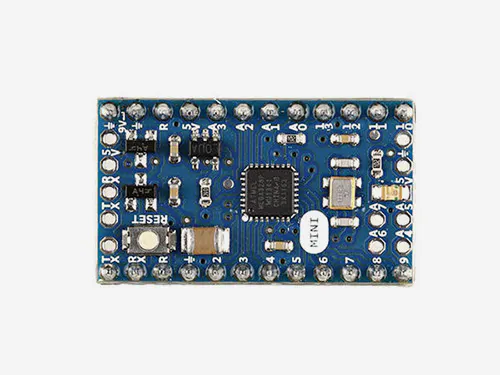
- Arudino Mega
- Breadboard
- 12V power supply
- 12V fan
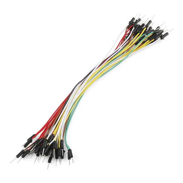
- Jumper cable
- 220 Ohm resistor
- NPN Transistor number: BC546B D6
Wiring
![]()
For the wiring we proceed according to the sketch . The 12V power supply is connected to the breadboard. We connect the – of the breadboard with GND of the Arduino (the short blue cable connection). Then the + of the breadboard to Vin of the Arduino Mega (red cable between Arduino and breadboard).
If we would plug the 12V power supply into the socket now. Then our Arduino would already be powered. There is no additional power supply like USB required. The Vin pin of the Arduino automatically regulates the 12V of the power supply to 5V for the Arduino.
Now we plug the NPN transistor into the breadboard. We connect the base (B) to the 220 Ohm resistor and then to pin 13 (yellow connection in the picture). We connect the collector (C) of the transistor directly to the negative connection of the fan (black fan cable). The positive fan connector is connected to the + of the breadboard. We connect the emitter (E) of the transistor to the – of the breadboard. That’s all for the wiring! Time for the Arduino code!
The code for the Arduino fan controller
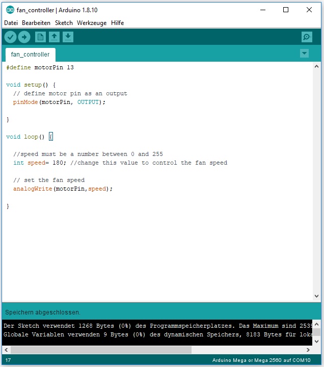
The Arduino code is absolutely simple and can be easily integrated into any existing Arduino program. Since we have connected the base of the transistor to pin 13, we define it as “motorPin”. The speed of the fan can then be controlled via the “speed” variable. A value between 0 and 255 must be selected for the speed. Depending on the fan model, a minimum speed is necessary for the fan to start.
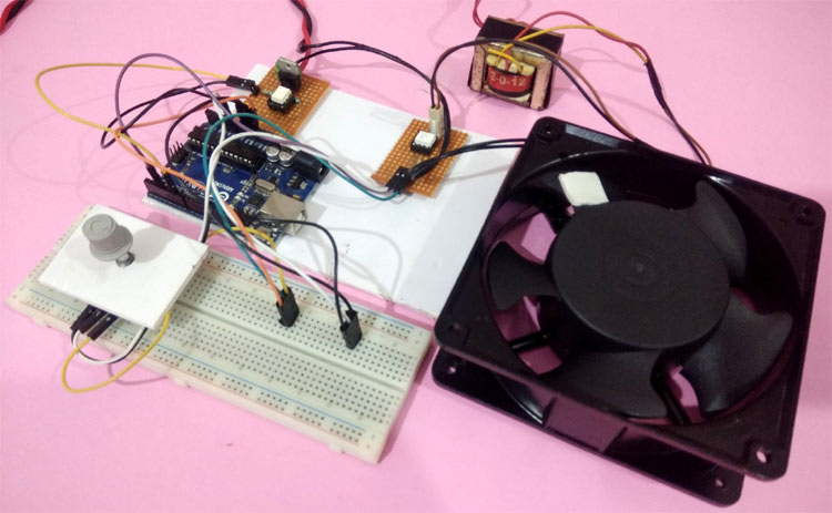
AC Fan Speed Control using Arduino and TRIAC
WARNING!! The circuit diagram discussed in this project is only for educational purposes. Be advised that working with 220V AC mains voltage requires extreme precaution and safety procedures should be followed. Do not touch any of the components or wires when the circuit is in operation.
It is easy to turn on or off any home appliance by using a switch or by using some control mechanism as we did in many Arduino based Home Automation projects. But there are a lot of applications where we need to control the AC power partially, for example, to control the speed of the Fan or the intensity of a Lamp. In this case, the PWM technique is used, so here we will learn how to use Arduino generated PWM to control AC fan speed with Arduino.
In this project, we will demonstrate Arduino AC fan speed control using TRIAC. Here phase controlling method of the AC signal is used to control the AC fan speed, using PWM signals generated by Arduino. In previous tutorial, we controlled the DC fan speed using PWM.
Components Required
- Arduino UNO
- 4N25 (Zero crossing detector)
- 10k Potentiometer
- MOC3021 0pto-coupler
- (0-9)V, 500 mA Stepdown Transformer
- BT136 TRIAC
- 230 VAC Axial AC fan
- Connecting wires
- Resistors
Working of AC fan control using Arduino
The working can be divided into four different parts. They are as follows
1. Zero-Crossing Detector
2. Phase Angle Controlling circuit
3. Potentiometer to control the Fan speed amount
4. PWM signal Generation circuit
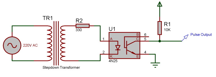
1. Zero-Crossing Detector
The AC supply we get in our household is 220v AC RMS, 50 HZ. This AC signal is alternating in nature and changes its polarity periodically. In the first half of every cycle, it flows in one direction reaching a peak voltage and then decreases down to zero. Then in the next half-cycle, it flows in alternate direction (negative) to a peak voltage and then again comes to zero. For controlling the speed of AC Fan, the peak voltage of both the half cycles needs to be chopped or controlled. For this, we must need to detect the zero point from which the signal is to be controlled/Chopped. This point on the voltage curve where the voltage changes the direction is called zero voltage crossing.
The circuit shown below is the zero crossing detector circuit which is used to get the zero-crossing point. First, the 220V AC voltage is stepped down to 9V AC using a step-down transformer and it is then fed to a 4N25 optocoupler at its pin 1 and 2. 4N25 optocoupler has an inbuilt LED with pin 1 as anode and pin 2 as a cathode. So as per the circuit below, when the AC wave goes closer to the zero-crossing point, the inbuilt LED of 4N25 will get turned off and as a result, the output transistor of 4N25 will also get turned OFF and the output pulse pin will get pulled up to 5V. Similarly, when the signal increases gradually to the peak point, then the LED turns ON and the transistor will also turn ON with the ground pin connected to the output pin, which makes this pin 0V. Using this pulse, the zero-crossing point can be detected using Arduino.
2. Phase Angle controlling Circuit
After detecting the point of zero crossing, now we have to control the amount of timing for which the power will be ON and OFF. This PWM signal will decide the amount of voltage output to the AC motor, which in turn controls the speed of it. Here a BT136 TRIAC is used, which controls the AC voltage as it is a power electronic switch for controlling an AC voltage signal.
TRIAC is a three-terminal AC switch that can be triggered by a low energy signal at its gate terminal. In SCRs, it conducts in only one direction, but in the case of TRIAC, the power can be controlled in both directions. To learn more about TRIAC and SCR, follow our previous articles.
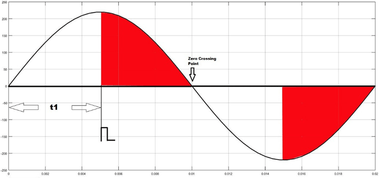
As shown in the figure above, the TRIAC is triggered at a firing angle of 90 degrees by applying a small gate pulse signal to it. The time “t1” is the delay time which is given as per the dimming requirement. For example, in this case, the firing angle is 90 percent, hence the power output will also be halved and hence the lamp will also glow with half intensity.
We know that the frequency of the AC signal is 50 Hz here. So the time period will be 1/f, which is 20ms. For a half cycle, this will be 10ms or 10,000 microseconds. Hence for controlling the power of an AC lamp, the range of “t1” can be varied from 0-10000 microseconds.
Optocoupler:
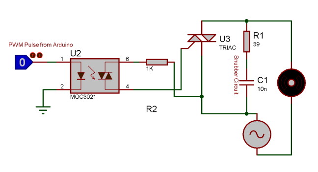
Optocoupler is also known as Optoisolator. It is used to maintain isolation between two electrical circuits like DC and AC signals. Basically, it consists of an LED that emits infrared light and the photosensor which detects it. Here a MOC3021 optocoupler is used to control the AC Fan from the microcontroller signals which is a DC signal.
TRIAC and Optocoupler connection diagram:
3. Potentiometer to control the Fan Speed
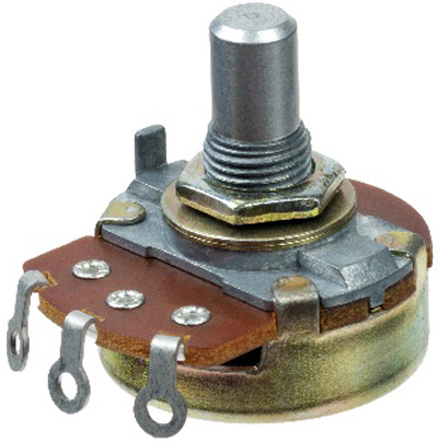
Here a potentiometer is used to vary the speed of AC Fan. We know that a potentiometer is a 3 terminal device that acts as a voltage divider and provides a variable voltage output. This variable analog output voltage is given at the Arduino analog input terminal to set the speed value of the AC fan.
4. PWM Signal Generation Unit
In the final step, a PWM pulse is given to the TRIAC as per the speed requirements, which in turn varies the ON/OFF timing of the AC signal and provides a variable output to control the Fan speed. Here Arduino is used to generate the PWM pulse, which takes the input from the potentiometer and gives PWM signal output to TRIAC and optocoupler circuit which further drives the AC fan at the desired speed. Learn more about PWM generation using Arduino here.
Circuit Diagram
Circuit diagram for this Arduino based 230v fan speed control circuit is given below:
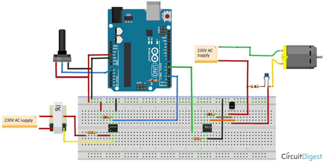
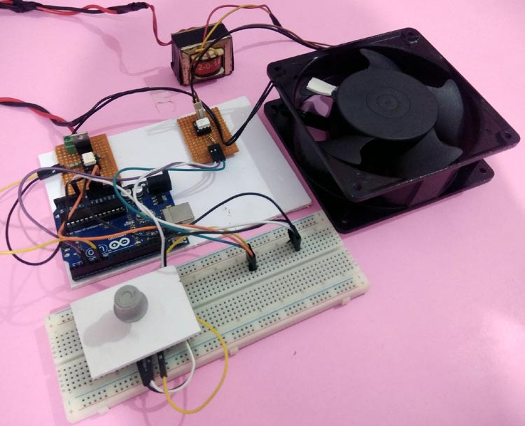
Note: I have shown the complete circuit on a breadboard only for the purpose of understanding. You should not use 220V AC supply directly on your breadboard, I have used a dotted board to make the connections as you can see in the image below
Programming the Arduino for AC fan speed control
After the hardware connection, we need to write up the code for Arduino, which will generate a PWM signal to control the AC signal ON/OFF timing using a potentiometer input. We previously used PWM techniques in many projects.
The complete code of this Arduino AC fan speed control project is given at the bottom of this project. The stepwise explanation of the code is given below.
In the first step, declare all the required variables, which are going to be used throughout the code. Here the BT136 TRIAC is connected to pin 6 of Arduino. And the variable speed_val is declared to store the value of speed step.
Next, inside setup function, declare the TRIAC pin as output as PWM output will be generated through this pin. Then, configure an interrupt to detect the zero-crossing. Here we have used a function called attachInterrupt, which will configure digital Pin 3 of Arduino as external interrupt and will call the function named zero_crossing when it detects any interrupts at its pin.
Inside the infinite loop, read the analog value from potentiometer which is connected at A0 and map it to a value range of (10-49).
To find out this range we have to do a small calculation. Earlier it is told that each half cycle is equivalent to 10,000 microseconds. So here the dimming will be controlled in 50 steps which is an arbitrary value and can be changed. Here the minimum steps are taken as 10, not Zero because 0-9 steps give approximately the same power output and maximum steps are taken as 49 as it is not recommended practically to take the upper limit (which is 50 in this case).
Then each step time can be calculated as 10000/50= 200 microseconds. This will be used in the next part of the code.
In the final step, configure the interrupt-driven function zero_crossing. Here the dimming time can be calculated by multiplying the individual step time with no. of steps. Then after this delay time, the TRIAC can be triggered using a small high pulse of 10 microseconds which is sufficient to turn on a TRIAC.
Complete code along with a working video for this AC fan control using Arduino and PWM is given below.
int TRIAC = 6;
int speed_val=0;
void setup()
<
pinMode(TRIAC, OUTPUT);
attachInterrupt(digitalPinToInterrupt(3), zero_crossing, CHANGE);
>
void zero_crossing()
<
int chop_time = (200*speed_val);
delayMicroseconds(chop_time);
digitalWrite(TRIAC, HIGH);
delayMicroseconds(10);
digitalWrite(TRIAC, LOW);
>
void loop()
<
int pot=analogRead(A0);
int data1 = map(pot, 0, 1023,10,40);
speed_val=data1;
>