Ethernet Shield
Ethernet Shield — это плата расширения, позволяющая Arduino или Iskra работать в локальных вычислительных сетях для приёма и передачи данных в сети Интернет.
На платы с разъёмом USB-B шилд может встать не ровно. Контакты разъёма ethernet прижимаются к металлическому разъёму микроконтроллера. Чтобы всё работало стабильно приклейте кусочек изоленты на разъём между шилдом и микроконтроллером или используйте специальные проставки
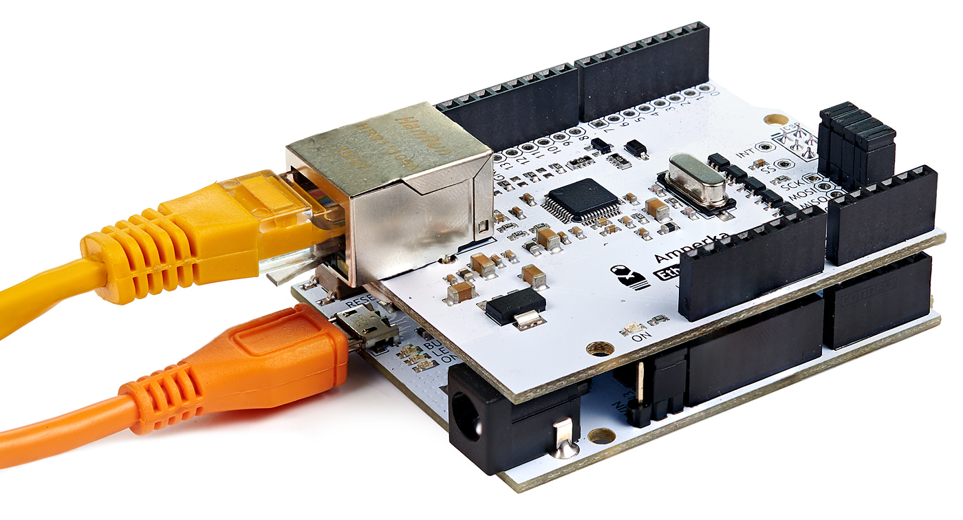
Шилд Ethernet позволит управлять удалёнными объектами через web-браузер со своего компьютера, планшета или телефона.
Подключение и настройка
Убедитесь в наличии и правильности соединения джамперов SPI-интерфейса на плате Ethernet Shield.
Примеры работы для Iskra JS
Для общения Ethernet Shield с платой Iskra JS воспользуемся библиотекой WIZnet. Она скрывает в себе все тонкости протокола, предоставляя простые и понятные функции.
Примеры работы для Arduino
Для общения Ethernet Shield с платами Arduino воспользуемся библиотекой Ethernet 2. Она скрывает в себе все тонкости протокола, предоставляя простые и понятные функции.
Пример WebClient
Пример WebServer
Создадим HTTP-сервер на порту 80, на который будем передавать значения всех аналоговых портов с A0 — A5 .
Элементы платы
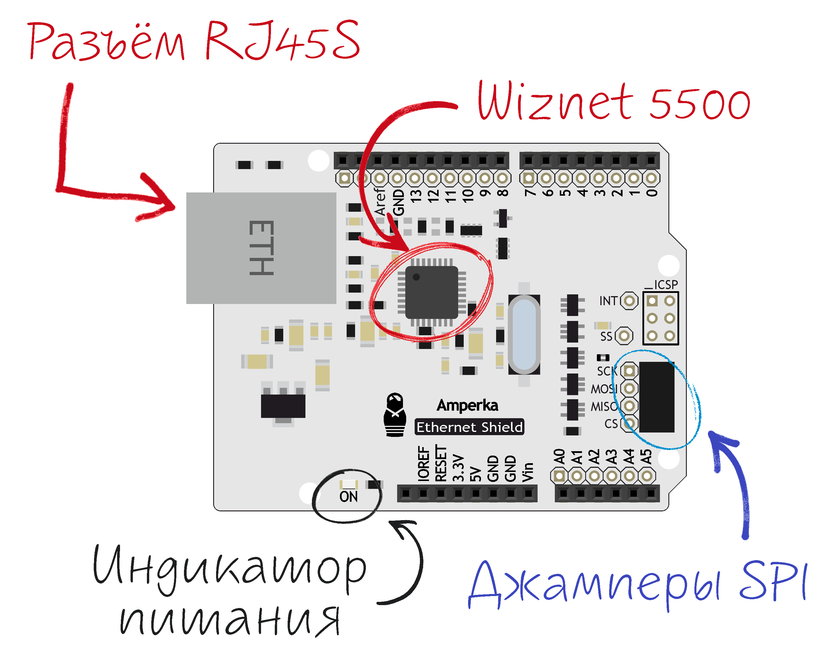
Микросхема Wiznet 5500
Чип wiznet 5500 — аппаратный контроллер TCP/IP, позволяющий легко подключиться к Интернету.
Светодиодная индикация
| Имя светодиода | Назначение |
|---|---|
| ON | Информационный светодиод о наличии питания |
Разъём RJ45S
Стандартный разъём для подключения Ethernet-кабеля.
Джамперы SPI
Коммутируют пины интерфейса SPI на Ethernet Shield и управляющей плате. Пины можно изменить, сняв джамперы и припаяв свободные металлические контакты к другим пинам с помощью проводков.
Ethernet Shield W5500 для подключения к сети Ethernet и Internet
Общие сведения:
Ethernet Shield W5500 — плата расширения, которая позволяет осуществить удалённое подключение плат Arduino к сети Ethernet, а следовательно и к сети Интернет (при наличии подключения).
Видео:
Спецификация:
- Напряжение питания: 5В;
- Интерфейс: SPI;
- Сетевые протоколы: TCP, UDP;
- Сетевые интерфейсы: 10Мбит / 100Мбит;
- Размер внутреннего буфера: 32 кБайт;
- Режимы работы: дуплекс / полудуплекс;
- Светодиодная индикация;
Подключение:
Ethernet Shield W5500 совместим с различными микроконтроллерами Arduino, его можно установить на Arduino UNO, Leonardo, Mega.
Ethernet Shield W5500 устанавливается сверху на управляющую плату.
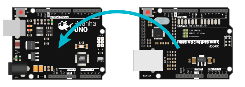
Подробнее о Ethernet Shield:
Ethernet Shield W5500 может стать вашим пропуском как просто в локальную или глобальную сеть, так и в мир интернета вещей, за счёт того, что позволит работать с большим количеством плат Arduino, которые вы можете расположить где только пожелаете.
Данный Shield может похвастаться сразу несколькими удачными техническими решениями, о которых мы и поговорим ниже.
Регулятор напряжения
Наличие данного регулятора позволит обеспечить стабильным питанием чип W5500, установленный на плате расширения. Обычно данный чип питают напрямую от вывода напряжения 3.3В на плате Arduino, но при просадке напряжения на самой Arduino чип, расположенный на Shield’у может начать работать не корректно. При питании чипа через регулятор такое точно не произойдёт, так как на вход регулятора подаётся напряжение 5В, которое уже преобразуется в сильные стабильные 3.3В.
Колодка SPI
Shield работает по шине SPI, а значит использует зарезервированные на этот случай выводы Arduino (для каждой платы — свои). Однако, все платы Arduino имеют специальную колодку с подписью ICSP, на которую выведены запараллеленные выводы шины SPI.
Ethernet Shield W5500 также имеет отдельную колодку, куда вынесены эти выводы, за счёт этого он легко устанавливается на большую часть плат Arduino/Piranha: UNO, ULTRA, MEGA, LEONARDO. Достаточно просто установить плату расширения сверху и всё, можно работать!
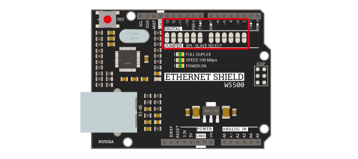
Перемычки
Выводы, которые выделены под шину SPI, зарезервированы на управляющих платах следующим образом:
- для Arduino UNO/ULTRA: MOSI — 11, MISO — 12, SCK — 13, SS — 10;
- для Arduino MEGA: MISO — 50, MOSI — 51, SCK — 52, SS — 53;
Однако, плата расширения Ethernet Shield позволяет изменить вывод SS на любой свободный цифровой вывод. Для этого на корпусе платы есть перемычки, на которых запаяна перемычка напротив 10 вывода. При необходимости (другое оборудование уже подключено к шине SPI либо к выводу 10) можно эту перемычку разомкнуть, а напротив нужного вывода запаять, тем самым изменив вывод SS (Select Slave) на нужный вам.
MAC адрес
MAC адрес (Media Access Control, управление доступом к среде) — уникальный шести байтовый идентификатор устройств сети Ethernet.
Библиотека Arduino IDE позволяет устанавливать любой MAC адрес для Ethernet Shield W5500. Хотя главное требование чтобы в локальной сети он был уникален, сетевое оборудование может не распознавать Ethernet Shield если старший байт MAC адреса неправильно настроен. В примерах ниже используется следующий MAC адрес:
| 0xDE | 0xAD | 0xBE | 0xEF | 0xFE | 0xED |
|---|---|---|---|---|---|
| Старший байт | — | — | — | — | Младший байт |
В случае, если необходимо настаивать несколько устройств в сети рекомендуется менять младший байт.
Примеры:
Проверка наличия Ethernet-соединения
Вывод IP-адреса, назначенного модулю
**На заметку: **В случае если на маршрутизаторе выключен DHCP или Вы хотите задать статическей адрес Shield’у, необходимо знать IP адрес маршрутизатора и маску подсети. В нашем случае адрес маршрутизатора 192.168.0.1 и маска подсети 255.255.255.0, это означает что Shield’у можно задать адреса в диапазоне от 192.168.0.2 до 192.168.0.254
Ethernet Shield V2.4
Overview
The Seeeduino V2.4 Ethernet shield can be used to provide your projects with internet connectivity. The shield features the W5200 Ethernet controller to support up to eight simulatneous TCP/UDP connections. The shield also has a microSD card slot to support projects which require storing large amounts of data for Internet of Things (IoT) applications. The RJ45 port (Where the Ethernet cable is connected to) is low enough to allow you to stack more shields on top of this one if needed.
Specification
- High speed Ethernet controller — W5200
- SPI interface
- 32 Kbytes inner buffer
- Minimal RJ45 Ethernet port
- Supports up to eight simultaneous TCP/UDP connections
- microSD card socket for data intensive projects
- Grove ports for I2C and UART
Shield Interface and Components
Overview
See the text below the image for a description of the components highlighted in the Ethernet shield.
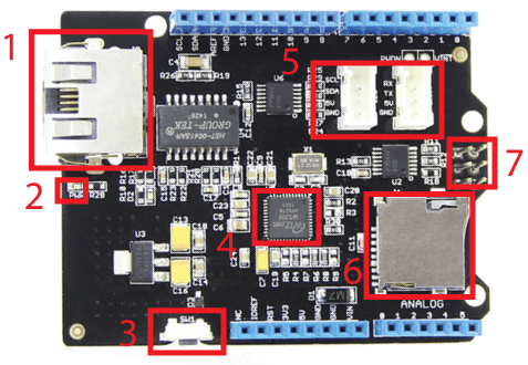
- Ethernet port RJ45: This is where you connect the Ethernet cable to the shield.
- PWR(Power) LED: is lit up green when the shield is receiving power from a source.
- SW1: Reset switch, resets the W5200 Ethernet controller and Arduino/Seeeduino board.
- W5200 Ethernet controller: This chip is what makes the TCP/IP communication possible. The SPI pins MOSI, MISO, SCK, and CS/SS of this chip are connected to digital pins 11, 12, 13, and 10 respectively.
- I2C and UART grove connectors: The UART connector is connected to digital pin 0 and 1 for RX and TX respectively. The I2C connector is connected to Analog pins 5 and 4 (bottom right of the siheld) for SCL and SDA as well as the pins SCL and SDA (top left of the shield).
- microSD card socket: A microSD card socket for projects that require memory storage. The SPI pins MOSI, MISO, SCK, and CS/SS of this socket are connected to digital pins 11, 12, 13, and 4 respectively.
- ICSP Connector:
Pins Used / Shield Compatibility
The Ethernet shield uses digital pins 11, 12, 13, 10, and 4 for SPI communication with the W5200 Ethernet controller and SD card. Therefore, the shield is compatible with any other shield that does not use pins 10, and 4 in this regard.
I2C and UART Pins:
The shield does not make use of this pins but provides easy access to them via the Grove connectors and pins described the Overview section above.
The shield is powered from the Vin, and 5V pins of the Arduino.
The RST pin is used by the SW1 switch, pressing this switch will reset both the W5200 Ethernet controller and Arduino board.
Seeeduino Ethernet Library
The library for this Ethernet shield’s is the same as the Arduino’s Ethernet library with the difference that we have replaced the W5100.h/cpp and socket.h/cpp files and references with versions that work with the newer W5200 controller which is what our shield has.
Setup
- Goto github and download the W5200 Ethernet Shield’s library.
- Unzip the downloaded file and paste the folder into your …/arduino/libraries/ folder.
- Start the Arduino IDE (or restart if it is open).
Usage
In addition to the various examples/applications we provide in this WiKi you may check out the Arduino’s «Ethernet library» reference page for a detail description of the classes and functions the library offers.
SD Card Library
As described in the «Overview» section of this WiKi, the Seeeduino Ethernet shield incorporates a microSD card port for storage/data intensive projects. The shield uses the SPI port to communicate with the microSD and is therefore compatible with the Arduino’s SD card library on pin 4 for chip select (CS).
Setup
The SD card library is already installed with the Arduino IDE in the arduino/libraries folder.
Ethernet Shield Examples/Applications
Example 1: How To Connect To an Internet Access Point / Router
Let The Access Point Automatically Assign an IP Address
The code below is the basic code needed to connect to an internet router or access point. The access point will automatically assign an IP address to Ethernet shield upon connection.
Use The IP Address You Want
Instead of letting the access point automatically assign a local IP address to your shield we can define the IP address:
and pass this value to the «begin» function:
There are some caveats to assigning your own defined IP address however:
- The IP address you select is required to be within the range of the IP address values your internet router or access point allows. You can find this range in your access point’s local network webpage, in some routers this will be under «DHCP Server Settings»‘s «Start IP Address» and «End IP Address».
- This version of the «begin» function returns a void value, so you cannot check if the DHCP connection was successful.
How To Find Your Router’s Page
- In Windows 7, click the start button and search for «Network».
- Click on «Network» to open the «Network Page»
- Your internet router should be listed under «Networ Infrastructure»
- Right click in your router then select «View device webpage»
- Your web browser should open and present you with the router’s settings webpage.
Example 2: Shield as Web Server
In this example we will show you how to use the Ethernet shield to serve a webpage to a web browser or any other device that requests it.
In the Arduino code we will create a server on port 80 (commonly used for HTTP), and when you visit the shield’s IP address on a web browser/client (e.g. Google Chrome, Firefox, Internet Explorer, Safari) the shield will respond back to the browser with a webpage.
Let’s talk a little bit about what happens in the background communication between the web browser and the Ethernet shield.
When you visit any website or IP address from a web browser the browser sends an HTTP Request to the server (in this case the Ethernet shield). The HTTP Request can vary by browser but a typical request looks like this:
Note: Notice that each of the request’s line ends with the two characters «\r\n», commonly known as carriage return (CR) and line feed (LN) respectively. We can use this to our advantage, in the Arduino code we will look for this pattern to know when the browser is done sending this information.
The server (Ethernet shield) will then need to send back an HTTP reply that may look like the following:
This is the HTTP reply we’ll send back from the Arduino to the web browser. You now know a little about HTTP request and are ready to get started serving webpages from your shield!
Stack the Ethernet shield on the Arduino and upload the code below to it.
Open the Arduino’s serial comm window and visit the IP address in a web browser. The webpage displayed will be similar to the following:

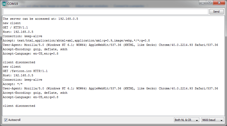
The output in the Arduino’s serial comm window should be similar to the following:
Example 3: Control The Arduino’s Digital Pins From a Webpage Served by The Shield
The Ethernet shield can be used not only to serve webpages but also receive information from them. In this example we will create a webpage with some buttons that will be used to toggle the Arduino’s digital pins, we will connect some LEDs so you can see the toggling in action.
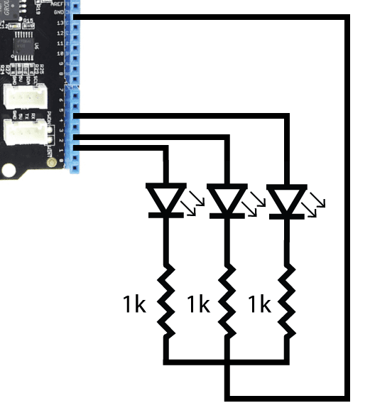
Connect three LEDs with current limiting resistors as shown in the schematic below:
The flow of the code is as follows:
- When the user «visits» the IP address in a web browser display a webpage with buttons
- Each button has an ID attribute whose value is the Arduino pin it will control.
- When a button is pressed send the pin value in a GET request in a parameter called «pin» to the shield.
- On the Arduino side, read the pin value and toggle the pin.
The webpage makes use of HTML, Javascript, and JQuery ( a Javascript library). If you would like to more about these two languages (HTML and Javascript) and the JQuery library visit http://www.w3schools.com/
Stack the Ethernet shield on your Arduino and upload the code below to it.
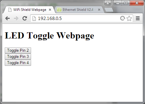
Open the serial monitor window and wait for the shield to respond with it’s assigned IP address. Now open your web browser and visit that IP address, a website like the one below should display:
Now press one of the buttons. The Arduino will toggle the LED/pin and reply back with the pin’s ON/OFF state in an alert dialog as shown below:

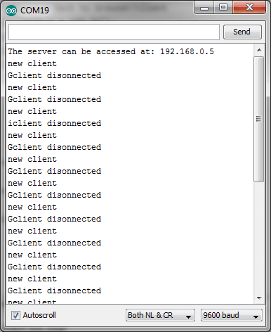
The Arduino’s serial monitor output should look like this:
Example 4: Request Weather Information From Any City in The World (Shield as Web Client)
A web client can be used to send and receive information from a web server, the Ethernet shield can be used as a client and we’ll show you how in this example. We’ll use an application programming interface (API) provided by OpenWeatherMap to request weather data from any city in the world. The way the OpenWeatherMap API works is you send the city name and country to their webserver and they reply back with weather data for that city.
The HTTP Request
For this example we’ll be requesting weather information for San Francisco, U.S. The HTTP request we have to send from the Arduino through the internet shield will have to look like this:
Note: The characters «%20″ are the URL encoded representation of the space » » character.
You can actually see the result our Ethernet shield will receive from api.openweathermap.org when it sends the HTTP request above by visiting this URL http://api.openweathermap.org/data/2.5/weather?q=San%20Francisco,ca
When you visit the URL you should see a JSON string similar to the following:
This JSON string contains the weather information, we’ll have to write some software to extract only what we need.
In the Arduino code we will extract the values of the «description» string, «Sky is Clear»; «temp», 286.75 (in Kelvins); and «humidity», 69 (in %RH). To extract these values all we have to do is use the find(xxx) function where xxx will be the characters before the values we are trying to extract, we will then continue reading the remaining values using read() until we have read all the values. The way we know when we have read all the values is by reading in a for loop until the character ‘ » ‘, «,», and «,» for description, temperature, and humidity respectively have been found.
Upload the code below to your Arduino and open the serial monitor window once the it’s done uploading.
The serial monitor window should print the following:

Example 5: Android App Communication With Shield
We’ve made a native Android app you can use to send HTTP data from a phone to the Ethernet shield. This app will send a pin number, depending on which button you press, to the Ethernet shield. When the Arduino gets the pin number it will toggle that pin and send the state of the pin back to the phone.

Android App Code:
Download the Android app (an Android Studio project) from this link:
Arduino Code and Circuit:
The code you need to upload to the Arduino is the one used in «Example 3: Control The Arduino’s Digital Pins From a Webpage Served by The Shield» of this WiKi page. The circuit is also the same.
The actually also works with our WiFi shield since all it does is send HTTP requests, you watch a video about it here:
Example 6: Chat Sever With Another Device/Terminal
The Ethernet shield can have a concurrent connection with another device to be able to send and receive data. In this example we’ll show you how to use the shield to create a chat service. The chat service will send data from the Arudino’s serial communication terminal to another PC/client’s terminal (you can use the same PC you use for your Arduino if you like).
Download a TCP Terminal:
Download and install RealTerm, a utility terminal that will allow use to connect to the WiFi shield.
The code works like this:
- Connect the shield to the access point to obtain an IP address
- When a client’s terminal sends data to the Arduino:
- If this is the first time print «We have a new client» in the Arduino’s terminal, and print «Hello, client!» to the client.
- If this is not the first time a message was sent simply print the text sent in the Arduino’s terminal.
- When you type something in the Arduino’s terminal and press the «Enter» key:
- Read the string and print in the Arduin’s terminal and send/print it to the client.
Upload the code below to your Arduino board and open the Arduino’s serial communication terminal, the shield’s IP address should be printed. Also do not close the Arduino’s serial comm. window.
Client Terminal Settings:
Open RealTerm and enter the Ethernet shield’s IP address and port as shown in the image below, then click the «Open» button. The «Connected» square should be green to signal a successful connection to the Arduino’s terminal.
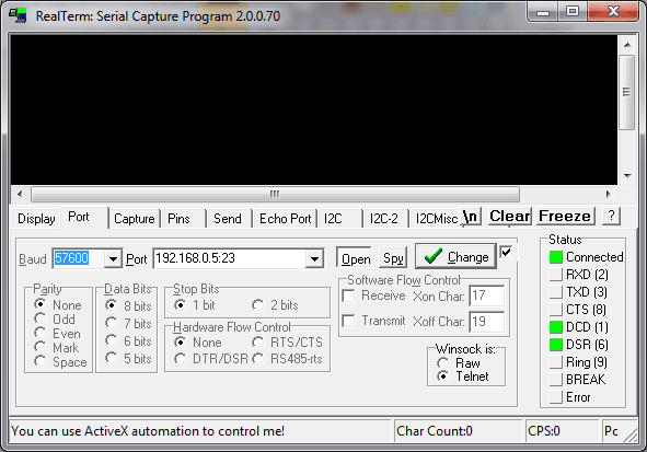
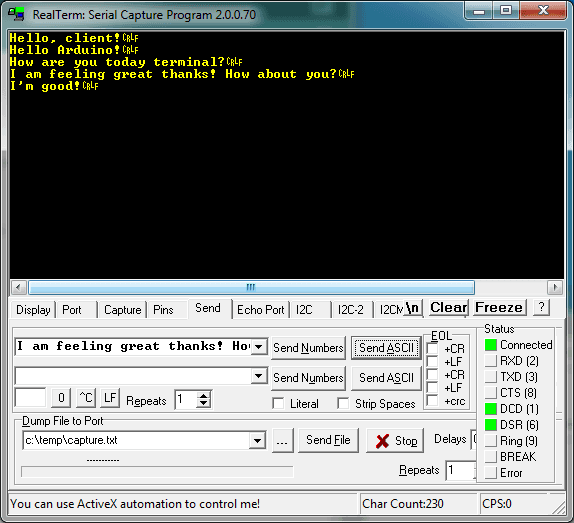
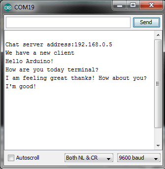
In RealTerm go to the «Send» tab, enter the text you would like to send to the Arduino’s terminal followed by «\r\n» and press the «SendASCII» button. You can also send messages from the Arduino’s terminal to the client’s terminal (RealTerm). The images below show a chat example’s ouput:
Example 7: How To Use The microSD card
The microSD card slot is connected to the Arduino’s SPI port with the CS line on digital pin 4. This means that the shield is compatible with the Arduino’s default SD card library and you can find numerous examples for it online.
We do provide an example you can use in our library, the example will write the Arduino’s analog pin values on the SD card as well as display them on a webpage.
To see this example:
- In the Arduino IDE go to File->Examples->Ethernet_Shield_W5200->WebServerWithSD
- Insert a microSD card into the shield’s microSD card slot and upload the code
- Don’t forget to change the IP address to one that your router is able to assign, or modify the code to allow the router to auto-assign one as described in «Example 1: How To Connect To an Internet Access Point / Router».
- Now open the Arduino Serial monitor window and in a web browser visit the Ethernet shield’s IP address, the analog pin values should be displayed and updated on the browser and will also be written to the SD card.
The important thing to keep in mind while using both the SD card and Ethernet functions of the shield is to deselect the SD card when using the Ethernet function
Application 1: Home Forecast Weather Station
We can make some great applications by combining the Ethernet shield with others. The application we’re going to make here is an internet connected weather forecast station, you will be able to see any city’s weather for the day in a touch screen.

The Touch Screen:
The touch screen we’ll be using is Seeedstudio’s 2.8 TFT Touch Shield V2.0.
How We Obtain Weather Data:
We’ll obtain San Francisco, US’ weather information the same way we did in «Example 4: Request Weather Information From Any City in The World (Shield as Web Client)», that is using the OpenWeatherMap API which we will then display on the touch shield.
In addition to the Ethernet shield’s software libraries we’ll make use of touch shield’s libraries which you can download from the «Resources» section in this wiki.
- Remove all power sources from your Arduino board.
- Stack the Ethernet shield on the Arduino, then stack the TFT Touch shield on the Ethernet shield.
- Now power up your Arduino and upload the code below
The weather data for San Francisco, U.S. should be displayed on the TFT touch shield and update every 10 seconds, the first time it might take a while (1 minute) since the Ethernet shield is initializing.
If you would like to change the units to the metric system use the following URL in your code:
Related Reading
Depending on the type of project you are working on you might have to learn a couple of different web languages. To help you get started we recommend the following website(s):
Resources
Related Projects
It’s a pity that we don’t have any demo about Ethernet Shield in the Recipe yet.
Post your awesome project about Ethernet Shield to win $100 Coupon! Please feel free to contact us: recipe@seeed.cc
Here we introduce some projects about LinkIt ONE.
What is LinkIt ONE
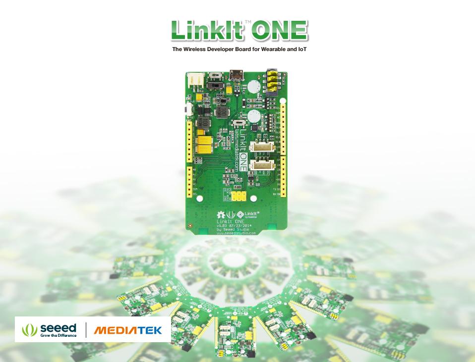
The LinkIt ONE development board is an open source, high performance board for prototyping Wearables and IoT devices.
It’s based on the world’s leading SoC for Wearables, MediaTek Aster (MT2502) combined with high performance Wi-Fi (MT5931)
and GPS (MT3332) chipsets to provide you with access to all the features of MediaTek LinkIt.
It also provides similar pin-out features to Arduino boards, making it easy for you to connect to various sensors, peripherals, and Arduino shields.
LinkIt ONE IoT Demo
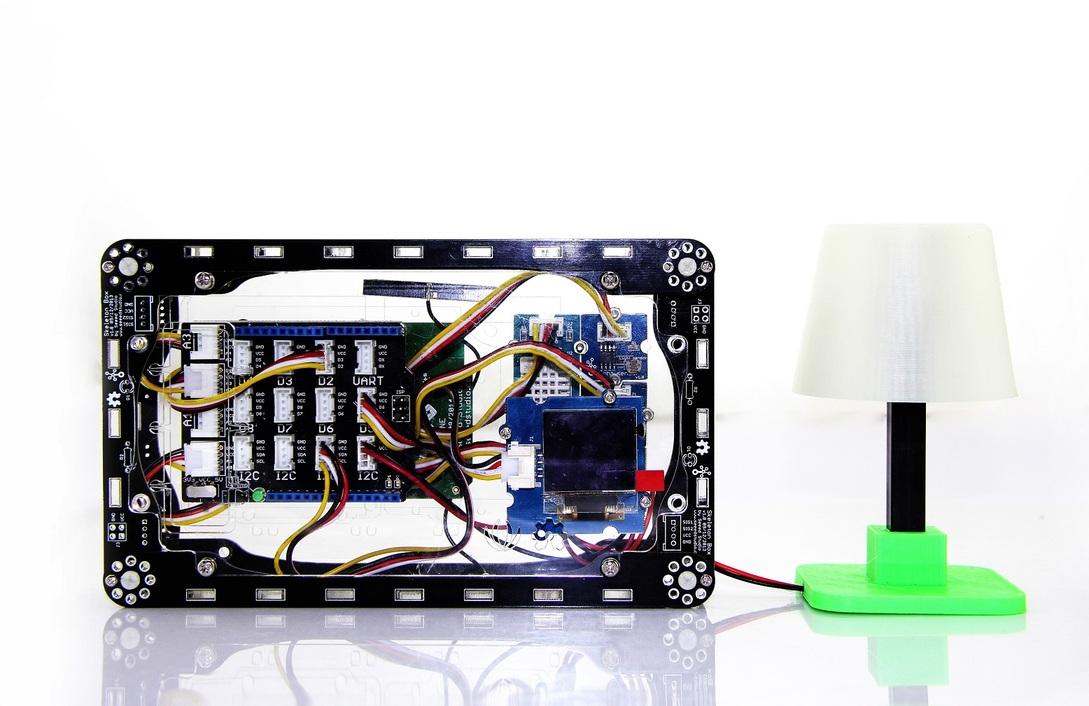
This is an IoT demo make by LinkIt ONE.
With this demo, we can:
- Display household temperautre, humidity, luminosity, volume control data collection on OLED screen
- Cloud service, data uploaded to Cloud platform Xively, real-time monitoring
- Data retention for reviewing how data changes over time
- Remote control Household Appliances by sending a message
- Table Lamp, 3D Printing, controlled by your phone
Pringles Can antenna with a LinkIt ONE
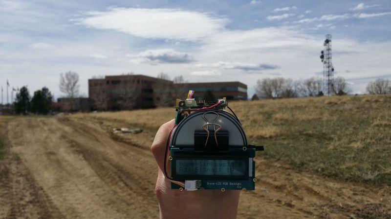
Make a focused antenna with a pringles can.
Share Your Awesome Projects with Us
Born with the spirit of making and sharing, that is what we believe makes a maker.
And only because of this, the open source community can be as prosperous as it is today.
It does not matter what you are and what you have made, hacker, maker, artist or engineers.
As long as you start sharing your works with others, you are being part of the open source community and you are making your contributions.
Now share your awesome projects with us on Recipe, and win a chance to become the Core User of Seeed.
- Core Users, are those who show high interests in Seeed products and make significant contributions on Recipe.
- We cooperate with our Core Users in the development of our new product, this, in another word, the Core Users will have the chance to experience any new products of Seeed before its official launch, and in return we expect valuable feedback from them to help us improve the product performance and user experience. And in most cases when our Core Users have some good ideas of making things, we’ll offer hardware pieces, PCBA services as well as technical support. Besides, further commercial cooperation with the Core Users is highly possible.
Get more information about Core User please email to: recipe@seeed.cc
Support
- Forum: Please visit our forum and post your questions here if you have any problem about products.
Licensing
This documentation is licensed under the Creative Commons Attribution-ShareAlike License 3.0 Source code and libraries are licensed under GPL/LGPL, see source code files for details.
