- Be cool admin
- How to add Arduino Library for Proteus and Simulate Arduino Projects
- Arduino Sensor Libraries for Proteus Simulation (Updated)
- What do I need to simulate Arduino in Proteus?
- Download and Install Arduino Proteus Libraries.
- 1. Arduino Board Library for Proteus
- 2. Genuino Proteus Library
- 3. GPS Library for Proteus
- 4. GSM Library for Proteus
- 5. Bluetooth Library for Proteus
- 6. XBee Proteus Library
- 7. Real-Time clock DS1307 Proteus Library
- 8. LCD Library for Proteus
- 9. Arduino Ultrasonic Sensor HC-SR04 Proteus Library
- 10. PIR Motion Sensor (HC-SR501) Library for Proteus
- Control Servo Motor with Arduino in Proteus
- Simple Control of Servo Motor with Arduino in Proteus
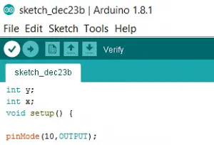
- Arduino Code for Servo Motor Control
- Proteus Simulation Results
- Control Servo Motor with Arduino using Push Buttons
- Arduino Code
- Proteus Simulation Results
Be cool admin
Самое высшее наслаждение — сделать то, что, по мнению других, вы сделать не можете.
Пока конструктор с ардуино где-то в пути, то разве это повод ничего не делать? Отдельно микроконтроллер ATmega (сердце ардуино) у меня был, но её нужно было бы программировать с помощью программатора, которого под рукой нет. Поэтому был выбран путь эмуляции, для этого понадобится компьютер на windows (желательно не ниже 7-ки), proteus, arduino ide. До того чтобы работать с настоящими ардуино можно использовать (Linux, Windows и Mac OS).
Первое что вам нужно это установить Proteus и запускать его с правами администратора, иначе некоторый функционал работать не будет. [Ссылка на wiki если вы никогда не слышали об этом программном обеспечении].
Заодно скачиваем библиотеку для Proteus с ардуино, он конечно может работать с ней по умолчанию, но выглядеть это будет не так красиво, да и некоторых плат нет, например UNO в моей версии из коробки отсутствовала. Поэтому идём на сайт (https://www.theengineeringprojects.com/2015/12/arduino-library-proteus-simulation.html) и качаем оттуда архив со всеми ардуино сразу или только для выбранной модели.
Как бы там не было у нас появится скаченный архив с файлами lib и idx, их нужно отправить в библиотеку Proteus, делается это очень просто. Смотрите где у вас установлена программа, открываете её и поднимаетесь на уровень выше и ищете папку LIBRARY куда и отправляете скаченные файлы.
После чего создадим пустой новый проект в Proteus. (Помните что программа должна запускаться с правами администратора).
Далее создаем проект по умолчанию, или можете выбрать любой другой размер, главное чтобы он был не пустой. На следующей вкладке не создаем PCB layout, так как сейчас это не нужно, и нажимаем далее, на вкладке firmware можно тоже всё пропустить и нажать далее. После того как мы нажмем финиш появится пустое поле для нашей схемы.
К ней добавим led (светодиод) и резистор на 300 Ом, а так же ground (землю искать в меню Terminals mode). В итоге должно получиться вот такая простая схема.
Теперь установим Arduino IDE (официальный сайт).
 Нам нужна версия для windows 7, версия без архива занимает 112 Мб
Установка очень простая, выбираем путь установки и в случае необходимости соглашаемся на установку дополнительных драйверов. Далее следует хорошая новость, даже две. 1-ая, писать программы для ардуино должно быть не сложно, вторая для проверки работоспособности платы в IDE уже есть установленные программы.
Сначала проверим версию ардуино платы в настройках.
После чего загрузим необходимый пример.
После чего остается всего пару шагов. Скомпилируем нашу программу для контроллера в меню Скетч — Проверить / Компилировать или кнопками Ctrl + R. И сохраним нашу программу, дав ей имя. После чего сделаем экспорт бинарного файла Ctrl + Alt + S. В конечном итоге нас интересует файл с самым длинным именем в сохраненной папке, у меня это — Blink2.ino.with_bootloader.standard.hex.
После копирования остаются последние штрихи, чтобы насладиться результатом. Загрузим нашу прошивку в микроконтроллер.
Нажмем правой клавишей мыши на изображении контроллера, выберем меню Edit Properties. В нём нас интересует строка Program File, выбираем скомпилированную прошивку, по идее она будет единственная в папке проекта. И нажимаем клавишу OK.
 Программа в работе (записано с помощью GifCam)
Вот и всё, можно наблюдать за проектом или начать делать следующий, самое главное, что работоспособность программ проверена.
Полезные сайты.
Wiki Амперка — разная информация об ардуино и не только на русском
Эмуляция Arduino в Proteus — сайт «практическая электроника» с которого я начал искать как произвести эмуляцию, один из первых в поиске.
Официальный сайт Arduino — сайт на английском языке, отсюда как минимум стоит взять IDE.
Proteus. Как добавить платы Arduino и получить прошивку hex в IDE — блог DIY, но сама инструкция по добавлению «кастомной» ардуино в proteus немного запутаная
How to add Arduino Library for Proteus and Simulate Arduino Projects
Arduino Uno is one of the most popular Development boards of our time. It can be used for almost any project that one can think of. But sometimes before making an actual circuit, it is a good idea to simulate that circuit first.
Simulating the circuit firsthand can save you from a lot of trouble. Proteus is one of the software that does this job brilliantly. And now you can simulate an Arduino in proteus before even implementing it in actual hardware. By the end of this post, you will know how to add Arduino Library for Proteus and simulate Arduino projects.
You can also watch the video given below for easy reference:
STEP 1: First of all download Arduino Library from the link given below:
Library Source : Find more interesting libraries at TheengineeringProjects
STEP 2: Download this file to the desktop of your PC.
STEP 3: Unzip the .zip file to the desktop of your PC.
STEP 4: Copy the two obtained files from the desktop.
STEP 5: Go to C:\Program Files (x86)\Labcenter Electronics\Proteus 7 Professional\LIBRARY
STEP 6: Paste the files here and you are done!
STEP 7: To use the Arduino Library, open proteus and click on “pick from libraries”
STEP 8: Search for “Arduino”, you will see 6 Arduino boards in the component section. Select the Board of your choice and start simulating!
How to simulate Arduino projects in Proteus?
PROJECT 1: Blinking an Led using Arduino Library for Proteus
STEP 1: Connect all the components as shown in the figure below.
STEP 1: Copy this “LED BLINKING ” program to your Arduino IDE:
STEP 2: Go to preferences
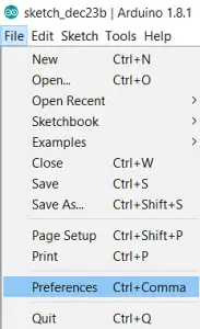
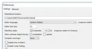
STEP 3: Check “Compilation” CheckBox
STEP 4: Click on verify (compile)

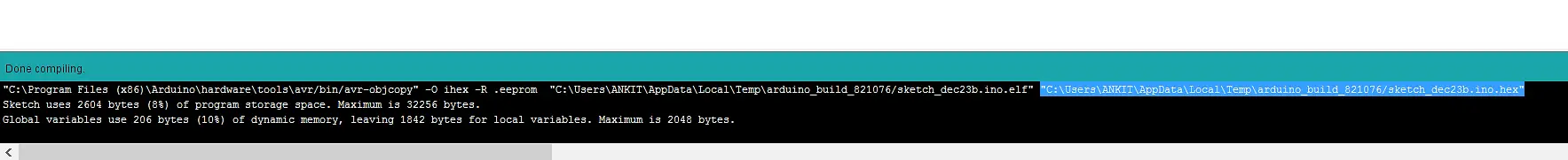
STEP 5: After compilation is complete copy the HEX file path from the bottom corner as shown below.
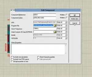
STEP 6: Open Proteus and double click on Arduino. Paste the file path and click ok
STEP 7: Run the simulation! Led at pin no. 13 will blink.
PROJECT 2: Analog I/P to control LED’s brightness using Arduino Library in Proteus
STEP 1: Connect all the components as shown in the simulation figure given below.
STEP 2: Copy this “PWM using Arduino ” program to your Arduino IDE:
STEP 3: Go to preferences from the File menu of Arduino IDE.
STEP 4: Check “Compilation” CheckBox as shown in the figure given below.
STEP 5: Click on verify (compile).
STEP 6: After compilation is complete copy the HEX file path from the bottom corner like before.
STEP 7: Now open the Proteus software and double click on Arduino. Paste the file path and click ok
STEP 8: Run the simulation. When the simulation is running, change the potentiometer’s wiper terminal position to control the brightness of the led. A screenshot of the working of this project is given below.
Arduino Sensor Libraries for Proteus Simulation (Updated)
Arduino Libraries for Proteus
This article is about Arduino sensor libraries for Proteus and how to get them into proteus to simulate your cool Arduino engineering projects.
If you have tinkered with Arduino for some time now, you have probably appreciated its unlimited possibilities. Also, if you have worked with the Proteus simulation program (Proteus CAD), I am sure you are addicted to it.
Now, will you be surprised if I tell you that, Proteus works hand in hand with the Arduino development board? Well, it does. And believe me, it does it well.
For instance, without a physical Arduino board, proteus software can be used to run your sketch (Arduino code). Similarly, you can make multiple circuit adjustments with proteus before doing the real project. You can see a 4-way traffic system developed in Proteus.
This will help you to arrest any circuit issues and programming bugs that may be introduced in the real project. Therefore, reducing the process of soldering, desoldering and resoldering of components and modules.
Table of Contents
What do I need to simulate Arduino in Proteus?
Well, you do not need any fancy software or trick. In fact, all that you will need is your usual Arduino IDE and a working Proteus with active simulation.
However, you can follow this article to read about programming language and install Arduino IDE if you don’t have already.
Also check these hand picked articles:
Moreover, the video below outlines how to install a new copy of Proteus and also how to fix existing Proteus crashing during a simulation.
If you followed the video to install the Proteus software, then you already have all the available Arduino sensor libraries installed. Otherwise, we would have to install individual modules that may be needed.
Download and Install Arduino Proteus Libraries.
1. Arduino Board Library for Proteus
First thing first, we can’t use the Arduino sensor or module without the Arduino itself. Therefore, we need to download and install the Arduino library below:
This library when downloaded and installed, allows you to design circuits and simulate with the following boards:
- Arduino Uno
- Mega (1280)
- Arduino Mega (2560)
- Mini
- Arduino Pro Mini
- Nano
2. Genuino Proteus Library
Both the Arduino and the Genuino Arduino sensor libraries for proteus have the same specification, pinout, and appearance. Therefore, you can use the Arduino library to design and simulate any project that will be implemented with the Genuino board.
However, you can download the Genuino library for proteus below.
The Genuino library includes the following boards:
- Genuino Uno
- Mega (1280)
- Genuino Mega (2580)
- Mini
- Mini Pro
- Genuino Nano
3. GPS Library for Proteus
GPS modules are used in navigation projects to track the location of a person, an artefact or a property. Download the library below to start designing and simulating GPS projects in proteus.
4. GSM Library for Proteus
With this library, you will be able to simulate any Arduino project that makes use of the GSM module. This library uses the AT command to control the GSM module over the serial communication. Download the library below.
The library was designed around the popular SIM900D GSM module. This module is also adaptable to SIM800.
5. Bluetooth Library for Proteus
This library was designed around the popular HC-05 and HC-06 Bluetooth modules. Also, it uses serial communication to send and receive data. Download the library below.
6. XBee Proteus Library
XBee is a bi-directional communication medium that allows the transfer and receiving of data over a radio high frequency. Download the XBee library for proteus ISIS below and start tinkering and simulating with your XBee projects.
7. Real-Time clock DS1307 Proteus Library
The DS1307 is a miniature real-time clock module that keeps time for your project. It can be called to display the current time and date and also to keep track of when an event occurred.
Download the RTC DS1307 library for proteus software below and start designing and simulating your awesome time-based projects.
8. LCD Library for Proteus
Bring your Arduino and other microcontroller projects to life with this amazing liquid crystal display (LCD) library for proteus. The library works for both 16×2 and 20×4 LCD modules. Download the library below and start making fun with your creative LCD projects.
9. Arduino Ultrasonic Sensor HC-SR04 Proteus Library
As the name implies, ultrasonic sensors employ sound waves to measure the distance between the sensor’s position and an object placed in front of it. These modules are typically used for obstacle avoidance devices (popularly applied in robotics) and for the electronic distance measuring instrument. Download the HC-SR04 ultrasonic sensor library for proteus simulation software below.
10. PIR Motion Sensor (HC-SR501) Library for Proteus
The Passive Infra-Red (PIR) motion sensor is used mostly for security and automation projects. They are used to detect the presence of an intruder in confidential places such as banks, offices, and home security. Download the library below and start simulating your security projects.
Control Servo Motor with Arduino in Proteus

Hello friends, hope you all are fine and having fun with your lives. Today’s post is about the Controlling of Servo Motor with Arduino in Proteus ISIS. Servo Motor is a common motor used in engineering projects for precise circular motion. We can move the servo motor at any desired angle, which is not possible in the case of other motors i.e. Stepper or DC.
For example, suppose I want to move an antenna at a precise angle of 47.5 degrees then if I use DC Motor, I have to use an encoder. So, in such cases instead of using a DC motor, I will prefer Servo Motor.
I have already posted Angle Control of Servo Motor using 555 Timer in which I have controlled servo motor using 555 timer and another tutorial about Controlling of Servo Motor using PIC Microcontroller in which I have controlled it with PIC16F877a. And today we are going to Control Servo Motor with Arduino and will design the simulation in Proteus ISIS.
First of all, we will have a look at simple control of servo motor with Arduino in Proteus ISIS and then we will check the control of the servo motor with Arduino using buttons in which we will move the servo motor to precise angles using buttons. So, let’s get started with it. :)
Simple Control of Servo Motor with Arduino in Proteus
- First of all, open your Proteus ISIS software and design the below simple circuit.
- You should also have a look at these Proteus Libraries of Components.
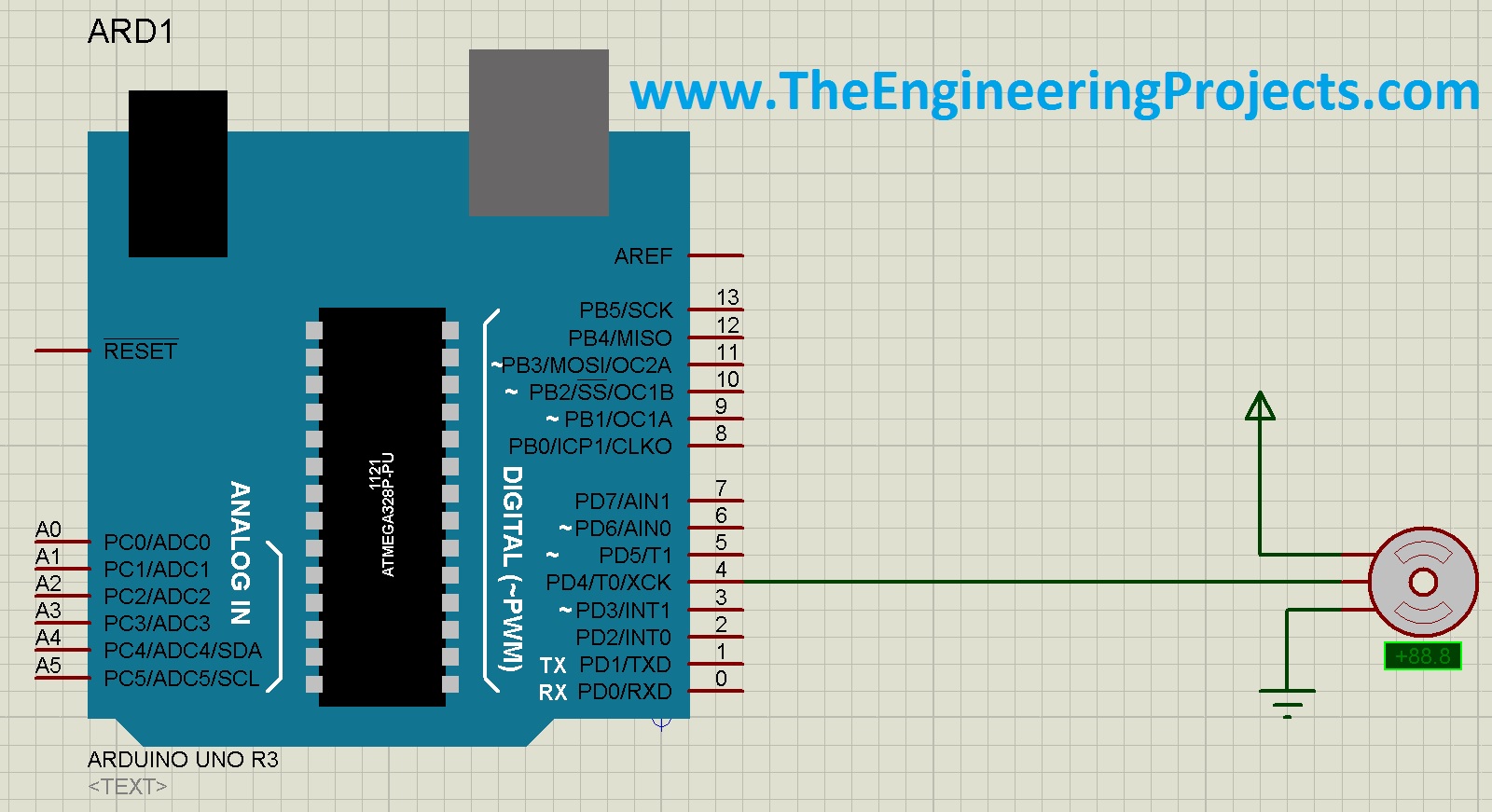
- Servo Motor has three pins:
- First Pin is Vcc .
- Second Pin is Control Pin .
- Third Pin is GND .
- The center pin is the controlling pin and goes to any digital pin of Arduino. I have connected the control pin to pin # 4 of Arduino.
Arduino Code for Servo Motor Control
- The next thing we need to do is to design the code for Arduino. So, open your Arduino software and copy paste the below code in it.
- Now compile this code and get your hex file.
- It’s the same code as given in the Servo folder of Examples in Arduino software.
- Upload your hex file to your Proteus Arduino board.
Note :
- You should read How to get Hex File from Arduino if you don’t know already.
Proteus Simulation Results
- Now, run your simulation and you will see that your Servo motor will start moving from 90 degrees to -90 degrees and then back to 90 degrees and will keep on going like this, as shown in the below figures:
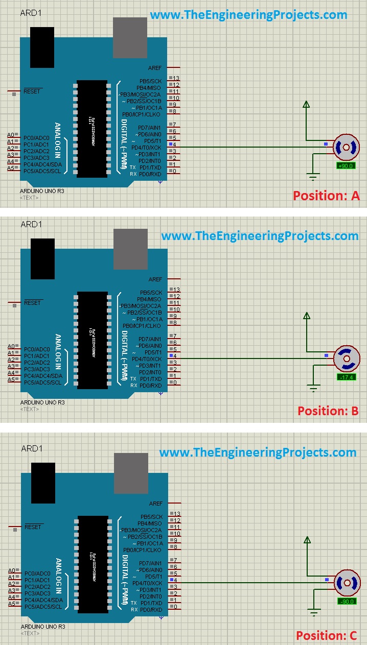
- Now when you start it, first of all, it will show Position A in the above figure then will move anticlockwise and pass the position B and finally will stop at Position C and then it will move clockwise and comes back to Position A after passing Position B.
- In this way, it will keep on moving between Position A and C.
- Till now we have seen a simple control of Servo Motor with Arduino in Proteus ISIS, now let’s have a look at a bit complex control of servo motor with Arduino.
Control Servo Motor with Arduino using Push Buttons
- In the previous section, we have seen a simple Control of Servo Motor with Arduino in which we simply moved Servo motor from 90 degrees to -90 degrees and vice versa.
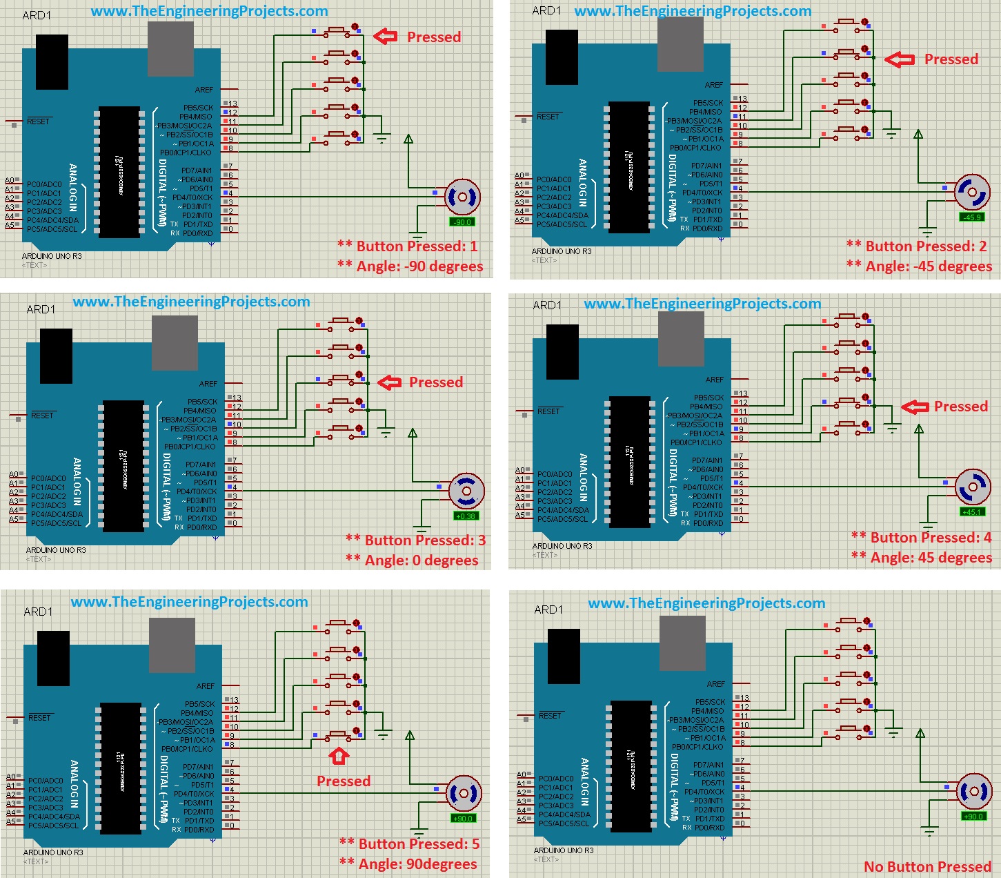
- Now I am going to control Servo motor using five push buttons and each push button will move the Servo motor to a precise angle.
- So, first of all, design a small design as shown in the below figure:
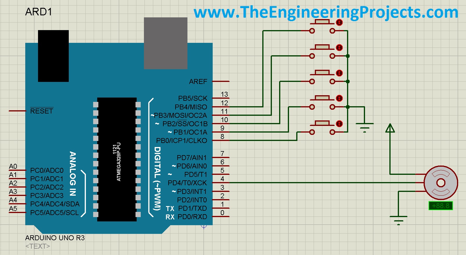
- I have added five buttons with Arduino and now with these five buttons, I will move the Servo motor to 90, 45, 0, -45 and -90 degrees . So, each button has its precise angle and it will move the motor to that angle only.
Arduino Code
- So, now the next thing is the code, copy paste the below code in your Arduino software and get the hex file:
- Upload this hex file to your Arduino board in Proteus and run the simulation.
Proteus Simulation Results
- Now press these buttons from top to bottom and you will get the below results:
- The above figure is quite self-explanatory but still, I explain a little.
- In the first figure, I pressed the first button and the motor moved to -90 degrees .
- In the second figure, I pressed the second button and the motor moved to -45 degrees .
- In the third figure, I pressed the third button and the motor moved to 0 degrees .
- In the fourth figure, I pressed the fourth button and the motor moved to 45 degrees .
- In the fifth figure, I pressed the fifth button and the motor moved to 90 degrees .
- In the sixth figure, all buttons are unpressed and the motor remained at the last position.
It was quite simple and hope I explained it properly. If you still have any questions then ask in the comments and I will try to resolve them. That’s all for today, will see you guys in the next tutorial. Take care . :)