OLED часы на arduino
На днях я решил создать часы на arduino с отображением времени, текущей даты, дня недели и температуры воздуха на OLED дисплее. Что из этого получилось смотрите на видео.
Список необходимых компонентов:

и загружаем первый пробный скетч для проверки работоспособности дисплея и часового модуля
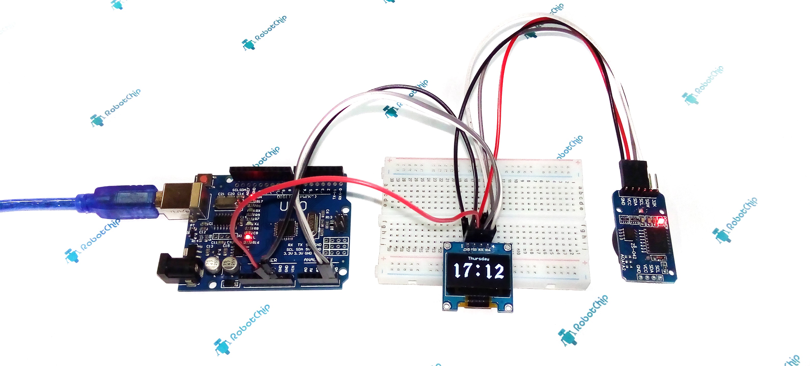
после загрузки скетча у нас на дисплее отобразятся часы как на фото

Как видим все отображается нормально, но что бы добавить русские названия дней недели нам потребуется инициализировать русские шрифты добавив строку в скетч
и еще добавить строки которые помогут нам определить порядковый номер дня недели и отобразить название дня на русском языке.
и еще закомментируем строки
что бы при повторной загрузке скетча не устанавливать заново время. После этого день недели на нашем дисплее отобразится на русском языке.

теперь изменим отображения месяца, добавив в скетч строки
Почему надписи в скетче отображаются непонятным набором символов читайте в этой статье Русские и украинские шрифты для OLED I2C дисплея
Теперь наши часики будут выглядеть как на фото.

Для тех, кому было лень править скетч, ниже есть готовый скетч.
Ну а теперь, еще более усовершенствуем наши OLED часы и добавим к ним отображение температуры, которую мы будем считывать с датчика температуры DS18B20.
Для отображения рисунка с градусником на OLED дисплее и значка градуса выберем картинку с рисунком градусника и с помощью графического редактора сохраним ее в формате GIF с именем term.gif, и тоже самое проделаем с картинкой с значком градуса — сохраним ее как grad.gif.
картинки должны быть двухцветными (белый и черный), доступные форматы картинок png, jpg, gif
У меня картинка term.bmp имеет размеры 19×40 пикселей, а картинка grad.bmp 13×12 пикселей. Потом нам потребуется конвертировать две картинки с помощью онлайн-сервиса www.rinkydinkelectronics.com

выбираем наш файл изображения и жмем Make File

Жмем на Click here to download your file и сохраняем файл grad.c в папку с нашим скетчем, тоже самое проделываем с другим изображением. Сохраняем и закрываем скетч. При повторном открытии он будет иметь еще две вкладки с файлами изображений.

После этого добавим две строки в скетч, которые инициализируют наши файлы изображений
а потом отобразим наши изображения на экране OLED дисплея, добавив строки
Добавим в наш скетч на два цикла. В первом цикле у нас будет отображаться время – назовем его void watch(); Второй цикл будет считывать и отображать температуру void temp();
А в основном цикле void loop(); пропишем для ротации циклов несколько строчек кода
В цикле void temp(); пропишем кусочек кода для считывания и отображения температуры
В цикле void watch(); пропишем наш код, который отвечает за отображение времени
После заливки скетча, наши OLED часы сначала должны отображать время, а потом температуру как на видео в начале статьи.
DS3231 RTC with Arduino. (Including Digital Clock using OLED Display)
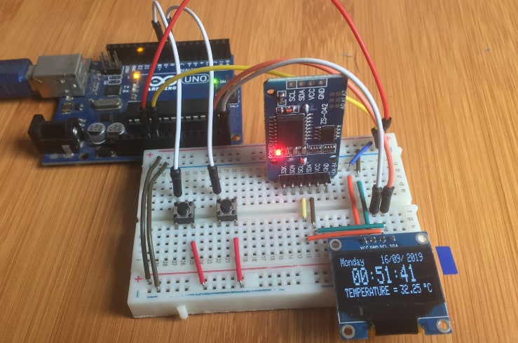
Table of Contents
Real time clocks (RTCs) like DS3231 RTC are required in applications where we need to keep track of the current time for example in data logging, clock timers and alarms.
Most microcontrollers, including the Arduino, have a built-in timer that can keep track of longer time periods like minutes or days. However, this timer only keeps track of time since the microcontroller was last powered which means that whenever the power is turned off, the timer is set back to zero!
Real time Clocks on the other hand are simply watches that keep track of date and time even when the power supply to the microcontroller is turned off because they have power backups. In this tutorial I will look at how DS3231 RTC module works and how to interface it with Arduino for keeping time.
You can also read about the DS1307 RTC, another common Real Time Clock that I have covered in another tutorial from the link below.
- DS1307 RTC With Arduino.
DS3231 RTC Hardware Overview.
The DS3231 RTC module comes with I/O pins on either side. These pins configuration is similar and you can use whichever side you prefer depending on the application.
The pinout of the DS3231RTC RTC is as follows;
SCL – Serial clock input for the I2C interface
SDA – Serial data input/output for the I2C serial interface.
VCC – 3.3V to 5V power supply for the module.
GND – Ground pin.
BAT – Backup 3V power supply for keeping track of time when the main power supply is turned off.
SQW – For outputting square-wave frequencies of 1Hz, 4kHz, 8kHz or 32kHz.
32K – Outputs a stable, temperature compensated and accurate reference clock.
The major coponent of this RTC module is the DS3231 chip which is a low-cost and extremely accurate RTC chip. It is responsible for all timekeeping functions and can easily be interfaced with any microcontroller via the I2C protocol.
The DS3231 RTC is driven by a 32kHz Temperature Compensated Crystal Oscillator (TCXO) which is packaged inside the chip. This Crystal Oscillator is highly immune to the external temperature changes that often affect oscillation frequency and this is the reason why the module is more accurate at time keeping than other RTC modules.
Right next to the integrated crystal is a temperature sensor which compensates the frequency changes by adding or removing clock ticks so that the timekeeping stays on track.
The on board 32 bytes 24C32 EEPROM chip can be used to save settings or really anything. The 24C32 EEPROM uses I2C interface for communication and shares the same I2C bus as DS3231. The I2C address of the EEPROM can be changed easily with the three A0, A1 and A2 solder jumpers at the back. Each one of these is used to hardcode in the address. If a jumper is shorted with solder, that sets the address.
There is a battery backup at bottom side of the board that holds a 20mm 3V lithium coin cell (any CR2032 battery can fit well) for maintaining accurate timekeeping when main power to the device is interrupted. So you don’t need to worry about power outages, your MCU can still keep track of time.
Connecting the DS3231 RTC to Arduino
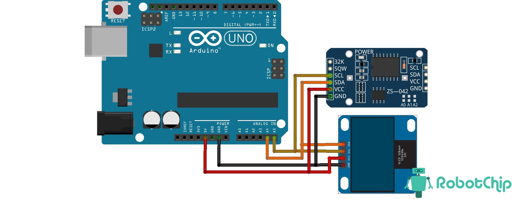
The DS3231 RTC uses I2C communication and will be connected to the Arduino Uno board as shown below.
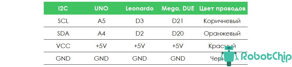
SCL to Pin A5
SDA to Pin A4
GND to Arduino ground
VCC to Arduino 5V.
Setting time of the DS3231 RTC
Before using the DS3231 rtc module, we need to first update it’s time and date settings. This is done by connecting the RTC module to an Arduino board and using already made libraries, we can be able to see the set time and date on the serial monitor.
The RTClib.h library is easy to use because it will automatically set the current date and time using the time on your computer. In case you need further reference on how to install the RTClib.h library from the Arduino IDE Library Manager you can check the link below where I describe in detail how this is done.
- Installing RTClib.h library from Arduino IDE Library Manager.
Code for setting the Time and Date for the DS3231 RTC using Arduino.
To set the time of the RTC, you can use the ds1307 example from RTClib library.
Go to File>Examples> RTClib> ds1307
This will open the code below for displaying time and date on the Serial monitor .
Code Explanation
The Wire.h library is needed for I2C communication and the RTClib.h library contains the classes and methods that enable us to read data from the RTC module.
Then an object rtc is created from the RTC_DS3231 class which is part of the RTClib library. Also a 2D character array for storing the days of the week is defined.
In the setup section, we initialize the RTC module using the begin() method and the lostPower() method reads the DS3231 RTC’s internal I2C registers to check if the chip has lost track of time. If the function returns true, we can then set the date and time.
The adjust() function is for setting the date and time. This is an overloaded function.
In order to set the date and time of the RTC to correspond to the time at which the code sketch was compiled, we use the statement below.
rtc.adjust(DateTime(F(__DATE__), F(__TIME__)));
The date and date set using the above method will correspond to that on your computer.
To be able to set a specific date and time you can use;
rtc.adjust(DateTime(YYYY, M, D, H, M, s));
For example to set January 28 2020 at 12:56 this would be rtc.adjust(DateTime(2020, 1, 28, 12, 56, 0));
Note: After setting the desired time these statements should be commented out of the code sketch to avoid repetitive resetting of the time and date whenever you want to upload anew program
The loop section contains a number of methods from the DateTime class including;
- now() method returns current date and time.
- year() , month() and day() functions return the current year, month and day respectively.
- dayOfTheWeek() function returns current day of the week.
- hour(),minute() and second() functions return current hour, minutes and seconds respectively
- unixtime() function returns unix time in seconds.
- TimeSpan() function is used to add or subtract time to or from the current time. For example now() + TimeSpan(seconds) returns the future time with seconds added into current time.
When this code is uploaded to the Arduino, you will be able to observe the date and time that has been set.
The time and date can also be set manually using the code below. In this case we need to change the setup part of the code where the time and date are set from this line of code below.
parse_cmd(«T300608330032016»,16);// this means 08:06:30 30.03.2016
//TssmmhhWDDMMYYYY(sec min hr day date month year)
After setting the time for the first time, the RTC stores the time and as such this line of code should be commented out for all other uses.
Displaying Time and Date of DS3231 RTC on 16×2 LCD.
I’ll now show you how time, date and temperature reading from the D3231 RTC module connected to Arduino can be displayed on a 16×2 I2C LCD.
Since both the RTC and LCD are using I2C communication then the clock (SCL) and data (SDA) lines of both modules will be connected to Arduino analog pins A5 and A4 respectively as shown below.
Code for displaying the time and date on LCD.
Digital clock using DS3231RTC with Arduino and I2C OLED display.
Finally, I’ll demonstrate how the DS3231 RTC module can be used to make a simple digital clock using Arduino and SSD1306 OLED. Before proceeding you should know how to interface the OLED with Arduino.
You can make reference from my other tutorial on how to use the SSD1306 OLED with Arduino using the link below.
The first setup for the DS3231 OLED clock we shall just simply connect the OLED and the RTC to Arduino so that we can display time and temperature.
The schematic of the setup is as shown below. Since both the SSD1306 OLED and the DS3231 RTC are I2C devices we just connect the corresponding pins as;
- SCL to Arduino analog pin A5
- SDA to Arduino analog pin A4
- GND to Arduino GROUND
- VCC to Arduino 5V
Code for Digital clock using DS3231 RTC and OLED Display.
The code is almost the same as was used in the previous tutorials only that this time we add the part for the OLED. In this case the date, time and temperature will be automatically updated and displayed on the OLED.
The display depends on the size of the OLED you are using. The above code is for a 128×32 display. You have to adjust the declaration of the width and height of the OLED and the parameters in the setCursor() function depending on the size of the display being used.
In the next setup of the DS32331 OLED clock we are going to use the memory storage capacity of the DS3231 RTC. We are going to include buttons to enable manual adjustment of the date and time which is written to the EEPROM of the RTC module. The schematic for this setup is shown below.
When this code is uploaded to the Arduino board, you can use the buttons to set the time and date which will be stored by the RTC and can keep accurately this set time even when the power supply to the microcontroller is turned off. The OLED will display the set time, date and temperature.
OLED часы (термометр) на arduino и DS3231
Автор: Сергей · Опубликовано 17.02.2017 · Обновлено 13.04.2020
В этой статье расскажу как собрать домашние часы и термометр (все в одном) на платформе Arduino c отображением времени (часы, день, неделя, месяц и год) и температуры. В качестве дисплея используем OLED матрицу (о данной матрице говорил в предыдущей статье), данные о температуре и времени считываем с часов реального времени RCT DS3231.
OLED часы (термометр) на arduino и DS3231
Необходимые детали:
► Arduino UNO R3 x 1 шт.
► OLED-дисплей 0.96, 128х64 x 1 шт.
► Провод DuPont, 2,54 мм, 20 см, F-M (Female — Male) x 1 шт.
► Кабель USB 2.0 A-B x 1 шт.
► Часы реального времени на DS3231 x 1 шт.
► Макетная плата MB-102 (Breadboard) x 1 шт.
Подключение:
Для вывода времени и температуры на OLED дисплей с модуля RCT DS3231, будем использовать плату Arduino UNO. Сразу оговорюсь, что данные о температуры обновляются примерно раз в минуты, так что не ждите быстрой реакции на изменении температуры. Теперь, собираем схему, которая показана ниже, для удобства дополнительно нарисовал таблицу подключения.
Так же, на модуль DS3231 уже предварительно настроено время (настройка времени на DS3231).
В примере используется две дополнительных библиотеки DS3231 и OLED_I2C, необходимо скачать их и установить, без них скетч не заработает. Далее, запускаем среду разработки IDE и копируем скетч (для удобства, добавлю файл для скачивания), если все правильно сделали, на OLED дисплее отобразится время.