ATTiny85 – Core Programming
Through some researches I did online on how to minimize components use, I stumbled with using an ATTiny85 chip to be used in the project. And through some more researching, I decided to have my new project done using the ATTiny85 Chip.

ATTiny85 Chip
I bought these chips from Ali-Express. First I need to study first the pin out of the ATTiny85, and relate this to the ATTiny85 Chip The image below shows the pin out of the integrated circuit.

The notch at the top of the chip indicates where pin 1 is, then the count continues consecutively counter-clockwise. Now, let’s look at the ATtiny85.
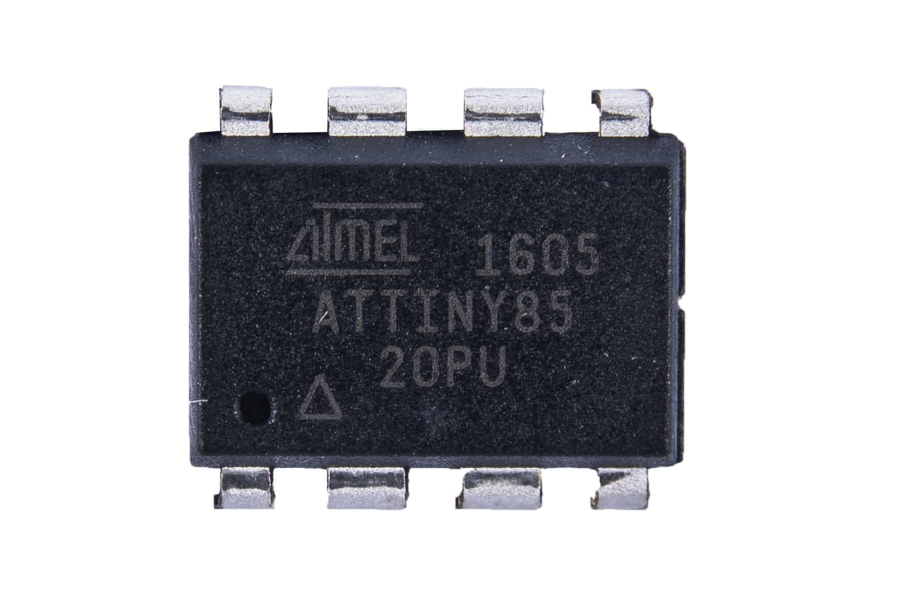
At the ATtiny85 IC diagram, we see the following pins labeled with PB0, PB1, PB2, PB3, PB4, and PB5. You will also see GND and VIN pins. These correspond to the Ground (Pin 4 of the IC), and Input Voltage (Pin 8 of the IC).
ARDUINO NANO TO ATTINY85 CONNECTIONS
Let’s connect the necessary pins together on both boards.
1 x Arduino Nano (or any Arduino board will do)
1 x ATtiny85
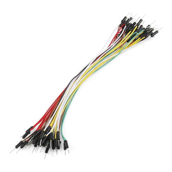
6 x Jumper Wires
1 x Electrolytic Capacitor – 10 µF
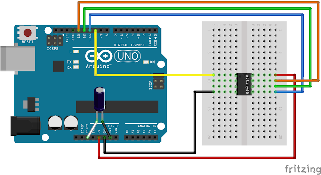
We need to connect the MOSI, MISO and SCK pins of both boards together (refer to the IC pin out), and Digital Pin 10 of the Arduino Nano to P5 of the ATtiny85.
Connect the following (I am using an Arduino Nano, so you have to take note the necessary pins of the board you are using when using it as an ISP).
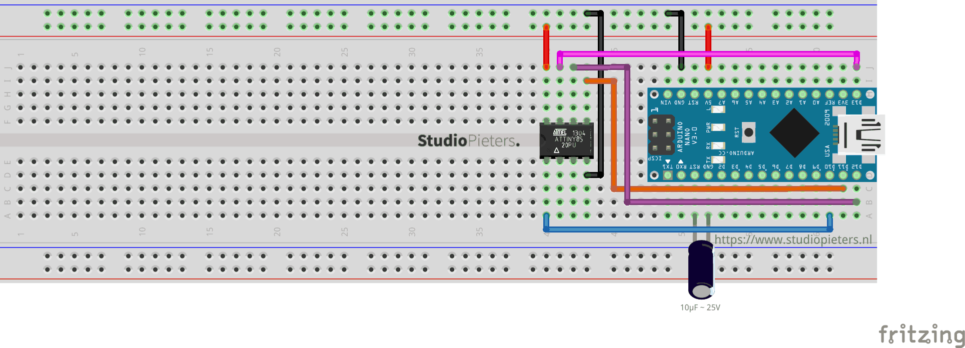
Add a 10uF capacitor between RESET and GND in Arduino. This is to avoid Arduino Nano from being auto reset when we upload the program to attiny85. If you are using a electrolytic capacitor make sure the anode goes in GND of Arduino Nano.
| Arduino Nano | ATTINY85 | |
| MOSI | Digital Pin 11 | PB0 (Chip Pin 5) |
| MISO | Digital Pin 12 | PB1 (Chip Pin 6) |
| SCL | Digital Pin 13 | PB2 (Chip Pin 7) |
| RESET | Digital Pin 10 | PB5 (Chip Pin 1) |
| VCC | VCC (5V) | VCC (Chip Pin 8) |
| GND | GND | GND (Any GND pin) |
There are two things we need to set up to successfully program the ATTiny85.
INSTALLING THE ATTINY BOARDS
Open the Arduino IDE Software then go to Arduino > Preferences. You will see Additional Boards Manager URLs. Add this link there, by pressing the rightmost icon. and ad this link:
Press OK (then another OK to exit from Preferences).
Now, go to Tools > Board > Boards Manager. Type attiny in the search field, and you should see attiny by David A. Mellis. Click it (attiny by David A. Mellis) and install the board. Now, you should see attiny boards from the list when you go to Tool > Boards. Scroll down to verify that the board is indeed installed.
ARDUINO AS ISP
Attach the Arduino Nano to your computer. Go to File > Examples > ArduinoISP, and click on Arduino ISP. Then go to Tools > Boards and select Arduino Nano (or your preferred board). Go to Tools > Port and select the port where your board is connected to. Upload the ArduinoISP sketch to your Arduino Nano (or your preferred board) by going to Sketch > Upload. At this stage, your Arduino Nano is ready to be used as a programmer.
Note: In some cases you need to select Processor : “ATMega328P (Old Bootloader)”

UPLOADING SKETCH TO ATTINY85 DEVELOPMENT BOARD
Make sure that the connections are as stated as described here above. Open the program / sketch you want uploaded to your ATtiny85. Go to Tool and setup the following.
| Board: | “ATtiny25/45/85” |
| Processor: | “ATtiny85” |
| Clock: | “Internal 8 MHz” |
| Port: | Select the port where your board is connected to. |
Then make sure Arduino as ISP is selected under Tools -> Programmer. By default the ATtiny85 runs at 1MHz. To make it to run at 8MHz select Tools -> Burn Bootloader.
Now open the Blink example from arduino examples and change the pin number from 13 to 0 and upload.
You can see the above message if everything was successful. Now we have upload the blink program to ATtiny85 and now lets test it out.
Testing ATtiny85 Blink
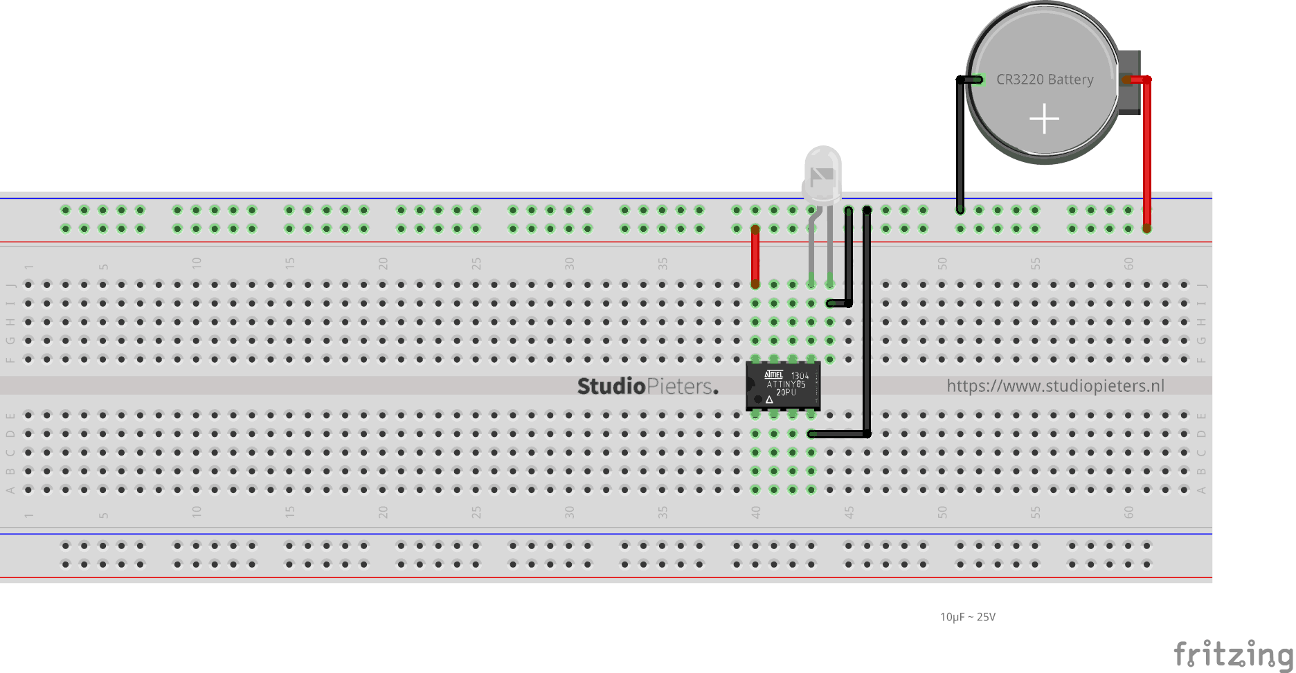
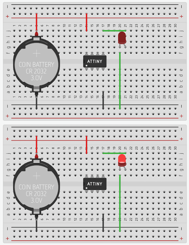
Now its time to test. Remove all connections from Arduino and take a power source. Here I will use a button cell to power ATtiny85.
There it is the blink program running on a ATtiny85 with just a battery cell to power it. You can do many projects with low cost, low power and low space. Only your imagination is the limit here and the number of PWM pins of course.
An ATtiny85 Deep Dive: Lesson 1 — Programming an AVR © GPL3+
For beginner Arduino programmers wanting to learn other AVR chips. The relative simplicity of the ATtiny85 is a great place to start!
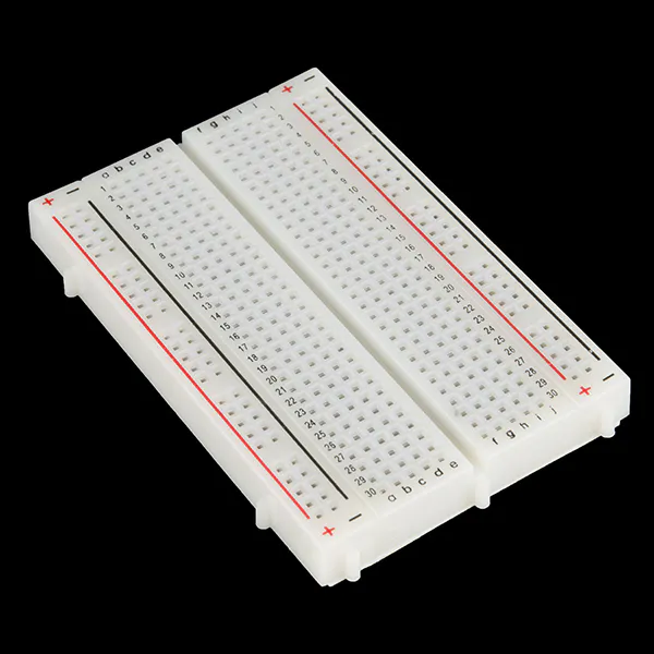
 |
| × | 1 | ||
_ztBMuBhMHo.jpg) |
| × | 1 | ||
 |
| × | 1 | ||
 |
| × | 1 | ||
 |
| × | 4 | ||
 |
| × | 4 |
Introduction and Prerequisites
This series focuses on the ATTiny85 AVR. No prior experience is necessary and we’ll use the familiar Arduino IDE for all lessons in this series. However, we will not be using the methods you may be familiar with to program the ATTiny, these include things like:
- pinMode()
- digitalWrite()
- digitalRead()
- analogWrite()
- analogRead()
- and delay(), we’ll never, ever use delay.
The reason we won’t be using these easy-to-use methods will become more apparent as you make your way through this series. Instead, we’ll be accessing the control registers built-in to the ATTiny (and every other AVR) to control the behavior of the MCU and peripherals. Some of the registers we’ll examine (in exhaustive detail) in future lessons of this series:
- Pin Control Registers
- Analog to Digital Converter (ADC) Control Registers
- Timer 0 (8-bit) Control Registers
- Timer 1 (8-bit) Control Registers
- Interrupt Control Registers
- MCU Control Registers
- EEPROM Control Registers
- Watch Dog Timer Control Registers
If you’re really serious about a deep dive into the ATTiny85, the very first thing you should do is download the ATTiny 25/45/85 datasheet from Microchip. I will be referring to it frequently throughout this series. Once you’ve mastered the ATTiny85, you’ll feel comfortable programming just about any AVR MCU product on the market, including the ATMega328 that’s at the heart of the Arduino Uno. For example, with a few jumper wire changes, the setup we’ll discuss below will program an ATTiny84 (the ATTiny85’s bigger cousin) to give you access to more functionality, as well as more input/output pins.
Some things that would be extremely helpful, but not mandatory for this series:
- Oscilloscope — I’ll include images of my oscilloscope for reference, but an oscilloscope in invaluable when experimenting with different PWM signals and monitoring other input and output signals.
- Multi-meter — Power will be a major discussion point. Most ATTiny projects will probably be small and be run from a coin cell battery. It’s very important to conserve power when we can. A multi-meter that can measure voltage and amperage in the milli and micro range will be very useful.
- Atmel Studio 7 coupled with a programmer/debugger — I mention Atmel Studio, because that’s the IDE I normally use. I’m an old-school Visual Studio developer and the environment is very familiar to me, and living without intellisense and auto-complete is not an option! The programmer/debugger I use is an AVR Dragon. It can be a finicky beast, but once you tame your Dragon, you’ll wonder how you ever lived without it. Using a feature built-in to most AVRs, named «debugWire, » you can set breakpoints in the code and inspect the ATTiny’s registers, variables and step through the code as it runs. There are newer products out there but you can pick up a Dragon for
Lesson 1 — Learning Objectives
- Understand the basic steps involved in uploading a program to a slave AVR device using the ISP protocol.
- Understand the basic concept of what the CS, MOSI, MISO and SCK signals are used for in the ISP protocol.
- Be able to download and install the prerequisite board package needed to program the ATTiny85.
- Be able to setup an Arduino Uno to act as an ISP programmer using the ArduinoISP sketch.
- Be able to write and upload a sketch to the ATTiny85 and observe the expected results.
- Understand the difference between the CPU and Peripheral devices within an AVR.
- Understand the basic principle and benefits of bitwise operators as they relate to AVR programming.
Upload a Sketch to an ATTiny — Step-by-Step-by-Step.
There are many ways to get your program onto an ATTiny device. I use an Tiny AVR Programmer and the AVR Dragon mostly, but we’ll be using an Arduino Uno for all lessons in this series to make sure everybody reading this can follow along.
Get your Arduino Uno Ready
We’ll be programming the ATTiny using an interface called In-System Programming (ISP), also known as In-Circuit Serial Programming (ICSP). Lucky for us, the Arduino IDE has an example sketch named ArduinoISP ready to go. Plug in your Arduino Uno, and load the example sketch into your Arduino IDE:
Про Ардуино и не только
четверг, 1 ноября 2018 г.
Знакомство с ATtiny85

Характеристики ATtiny85
- Память программ (FLASH) — 8КБ
- ОЗУ (SRAM) — 512 байт
- Энергонезависимая память (EEPROM) — 512 байт
- Тактовая частота — до 20МГц
- USI (Universal Serial Interface) — универсальный последовательный интерфейс. Может использоваться в двухпроводном (I2C/TWI) и трехпроводном (SPI) режиме
- 4-х канальный 10-разрядный АЦП
- Аналоговый компаратор
- 2 8-битных таймера-счетчика
- Сторожевой таймер
- 8 выводов, 6 из которых могут использоваться как линии ввода-вывода
- Напряжение питания 2.7 .. 5.5В
Более подробная информация о микроконтроллере ATtiny85 приведена в даташите.
Данных параметров вполне достаточно для решения ряда задач. И вы можете найти множество интересных проектов на базе ATtiny85, подтверждающих это (загляните, например, в мою публикацию Игральный кубик на ATtiny85). Также микроконтроллер поддерживает три режима энергосбережения для создания энергоэффективных устройств. Одним словом данный микроконтроллер заслуживает внимания, поэтому сегодня я расскажу о том, как программировать ATtiny85 в привычной нам среде разработки Ардуино.
Программирование ATtiny85 в IDE Arduino
Итак, программировать ATtiny85 будем в IDE Arduino, причем ее версия должна быть не ниже 1.6.4, а для прошивки нам потребуется программатор. В качестве программатора я буду использовать Ардуино Уно. Эта тема подробно описана в статье Arduino as ISP, поэтому сегодня не станем заострять на ней внимание. Можно использовать и другие программаторы, например, рассмотренный недавно USBasp. В этом случае пропустите следующий пункт и переходите к настройке IDE.
Подготовка программатора Arduino as ISP
Запускаем IDE Arduino, открываем скетч ArduinoISP (меню Файл > Примеры > ArduinoISP), подключаем Ардуино к компьютеру и загружаем в нее скетч. На этом плату Ардуино пока можно отложить, займемся настройкой IDE.
Добавление ATtiny85 в список плат IDE Arduino
В среде разработки Ардуино отсутствуют компоненты, необходимые для работы с микроконтроллерами tiny, поэтому сейчас нужно добавить их в IDE. Для этого скопируйте в буфер обмена следующую строку:
https://raw.githubusercontent.com/damellis/attiny/ide-1.6.x-boards-manager/package_damellis_attiny_index.json
Теперь в IDE открываем меню Файл > Настройки и в появившемся окне нажимаем кнопку рядом с полем ввода дополнительных ссылок для Менеджера плат. В открывшемся окне вставляем скопированную ранее ссылку новой строкой. Нажимаем OK для сохранения изменений и выхода из настроек:


Подключение ATtiny85 к программатору

Загрузка скетча в ATtiny85
Откроем скетч Blink из стандартных примеров Ардуино (меню Файл > Примеры > Basics > Blink). Заменим в скетче текст LED_BUILTIN на 0 в трех местах, должно получиться:
Теперь в списке плат выберем ATtiny25/45/85, конкретную модель микроконтроллера укажем в меню Процессор. В меню Clock выберем значение Internal 8MHz. И, поскольку в качестве программатора мы используем Ардуино, выберем значение Arduino as ISP в меню Программатор:
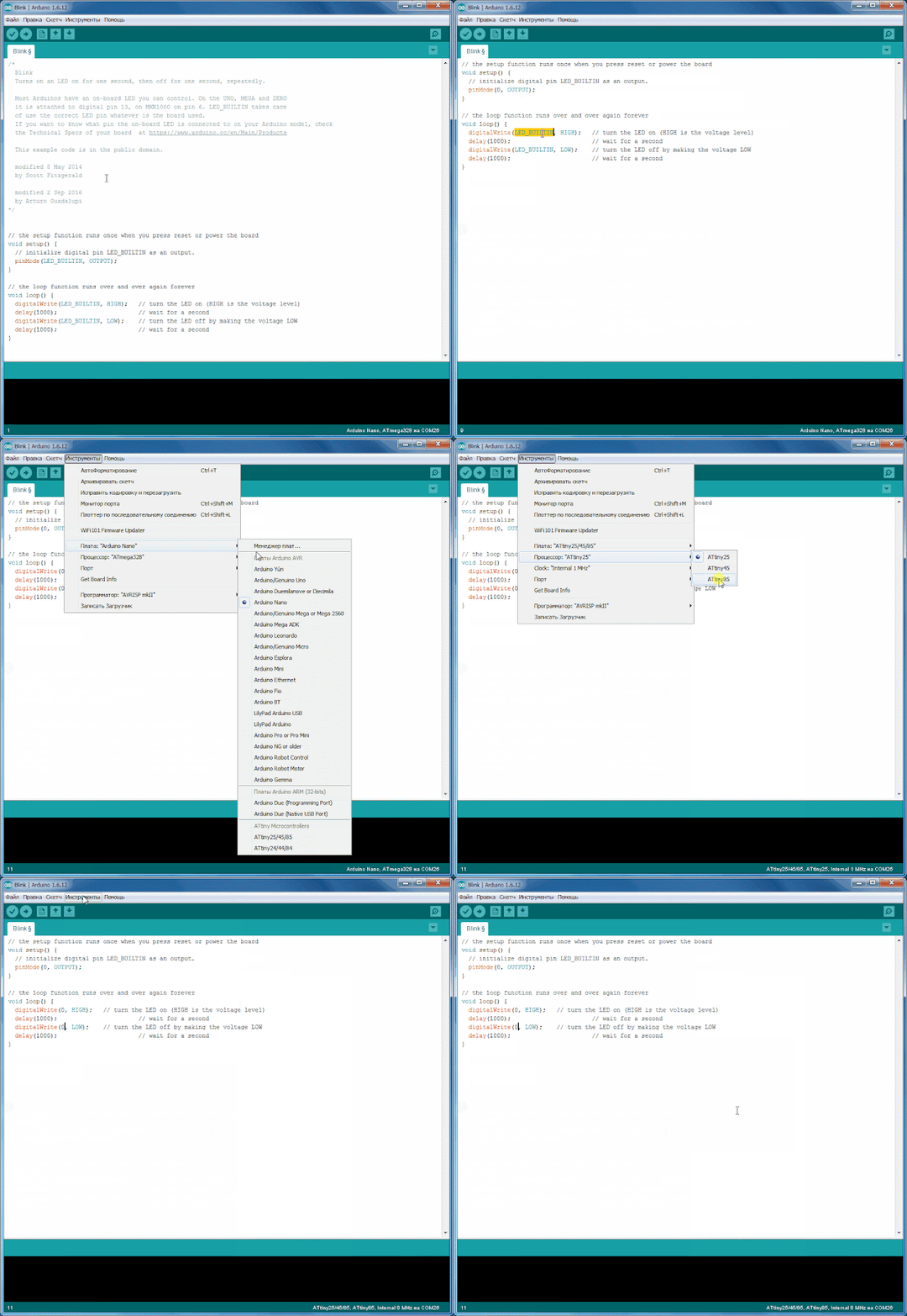
Теперь всё готово для загрузки скетча в ATtiny85. Подключаем Ардуино к компьютеру, нажимаем кнопку загрузки и дожидаемся сообщения о завершении операции.
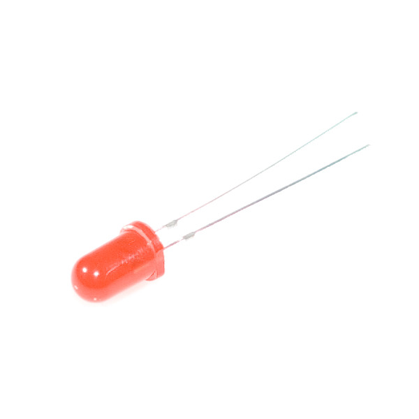
Для проверки работы скетча подключим к микроконтроллеру светодиод: длинным выводом к PB0, коротким к GND. Светодиод начнет мигать, только интервал составит не 1 секунду, а 8 (при условии, что мы имеем дело с новым/чистым микроконтроллером). И вот почему: новые микроконтроллеры идут с завода с запрограммированным фьюзом CKDIV8 (Divide clock by 8), что приводит к делению тактовой частоты на 8. Поэтому сейчас мы сбросим данный фьюз, чтобы микроконтроллер работал на частоте 8МГц.
Изменение тактовой частоты ATtiny85
Работу с фьюзами я уже описывал в статье Что такое фьюзы. Чтение и запись фьюзов Ардуино. Тогда для работы с ними использовалась программа avrdude. Но сейчас для сброса фьюза CKDIV8 мы поступим проще: установка конфигурационных байтов входит в процедуру записи загрузчика, поэтому в IDE Arduino переходим в меню Инструменты и выбираем команду Записать загрузчик. В действительности запись загрузчика в микроконтроллер не произойдет, т.к. его просто нет в используемом нами пакете. Но зато будут перезаписаны конфигурационные байты, новые значения будут взяты из файла boards.txt, в них как раз бит CKDIV8 сброшен. Также будет очищена память программ, поэтому скетч нужно будет загрузить в микроконтроллер еще раз.
После выполнения указанных действий ATtiny85 заработает на частоте 8МГц и светодиод начнет мигать с интервалом в 1 секунду. Микроконтроллер можно отключить от Ардуино и запитать от источника 3-5В.
Когда вы в очередной раз захотите изменить тактовую частоту ATtiny85, нужно будет выбрать соответствующее значение в меню Инструменты > Clock и повторно выполнить команду Записать загрузчик. И, как вы можете видеть, в меню выбора частоты доступно значение 16МГц — оно получается умножением тактовой частоты внутреннего RC-генератора (8МГц). Этой опцией не могут похвастаться даже старшие микроконтроллеры семейства mega. Такой способ тактирования применен в плате Digispark, построенной на ATtiny85.
