Самодельные диммеры для систем домашней автоматики
Привет всем! Эта статья про то, как собрать и применить диммеры для управления освещением. Схемы самые простые. Предназначены для сети 220 вольт переменного тока, управление — аналоговый сигнал 0-5 вольт (ардуино) или 0-3.3 вольта (esp8266).
1. Диммер для лампы накаливания, на транзисторе:
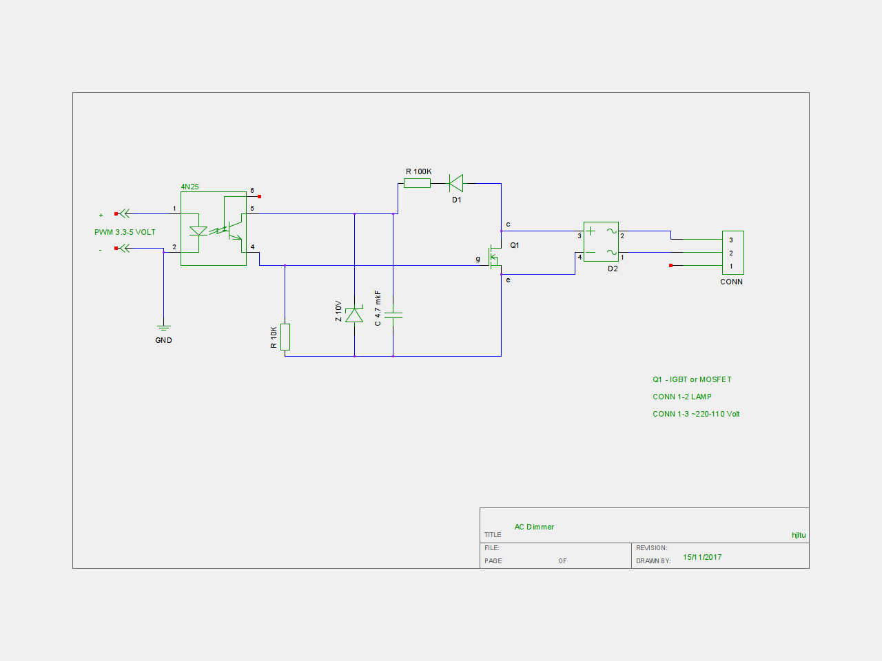
Q1 — IGBT транзистор IRG4BC30UD (необходим радиатор)
D1 — выпрямительный диод
D2 — диодный мост
Z 10V — диод зенера на 10 вольт
4N25 — оптопара
R 100K и R 10K — резисторы
C 4.7 — конденсатор
Принцип работы: усиление pwm сигнала с ардуино транзистором.
2. Диммер на симисторе, подходит для ламп накала и светодиодных диммируемых ламп:
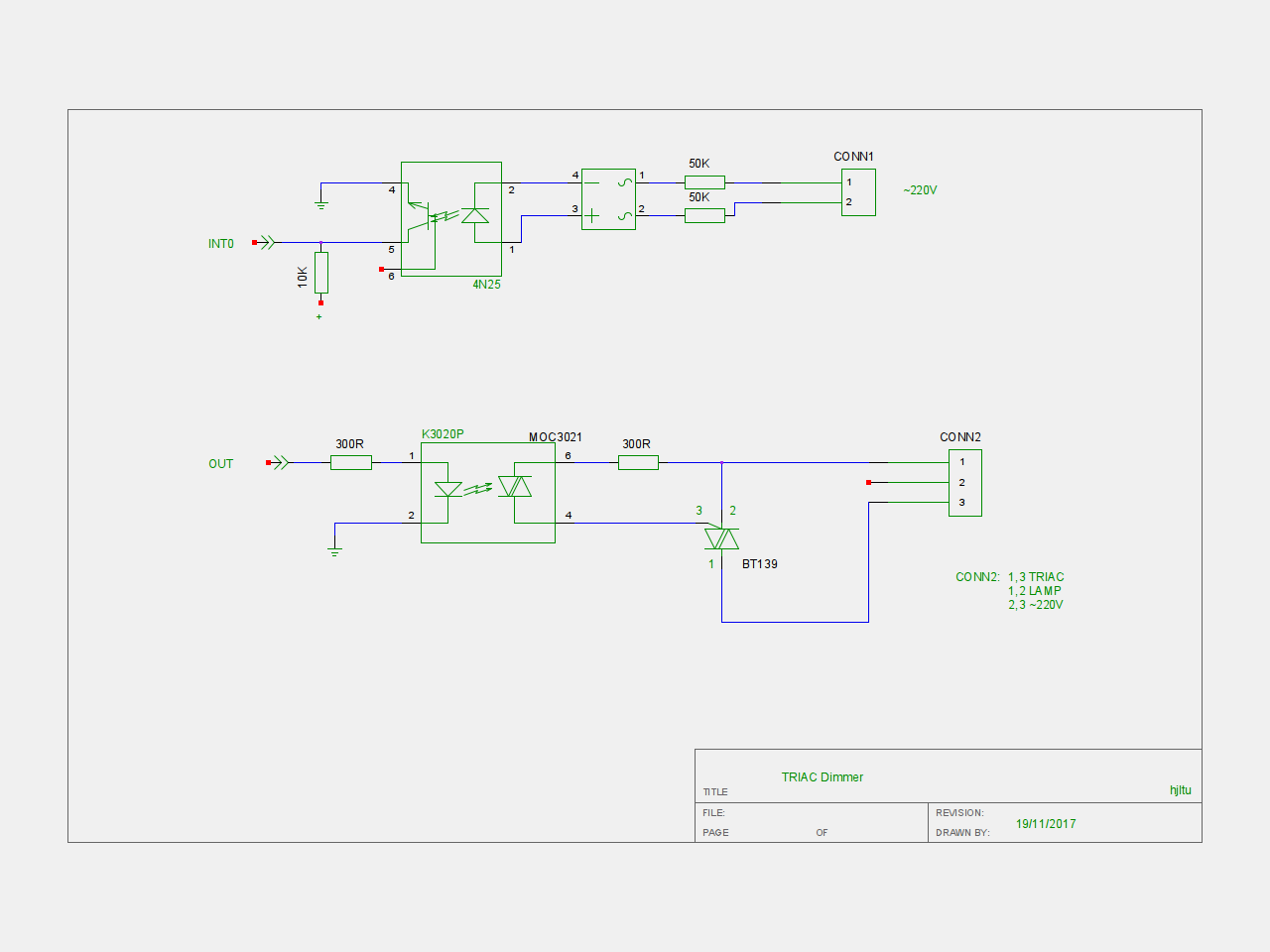
BT 139 — симистор
MOC 3021 и 4N25 — оптопары
R300, R10K, R50K — резисторы
Принцип работы: INT0 — вход на ардуино (pin2) настроенный на прерывание, на него приходит сигнал перехода фазы через ноль (детектор нуля).
OUT — выход с ардуины (pin3) с которого через задержку приходит сигнал на симистор.
Параметр диммирования задается через serial порт (0-255#)
Пример: 99#
Для более стабильной работы (например ложные сигналы прерывания) желательно добавить RC фильтр.
На этом все, спасибо за внимание, будте осторожны с электричеством.
Регулятор силы света (диммер) на Arduino и симисторе
В современных домохозяйствах большинство устройств (лампочки, телевизоры, кондиционеры и т.д.) запитываются от напряжения переменного тока. Мы можем управлять включением и выключением этих устройств с помощью платы Arduino и реле, эти способы управления домашними электронными устройствами рассматривались на нашем сайте в проектах автоматизации дома. Но если нам нужно не просто управлять процессами включения/выключения устройств, а нужно еще, к примеру, регулировать яркость свечения лампы или частоту вращения вентилятора, то здесь нам необходимо использовать методы управления фазами и статические переключатели наподобие симисторов (TRIAC) для управления фазами напряжение переменного тока.

В данной статье мы рассмотрим создание регулятора силы света (диммера, dimmer) лампы переменного тока на основе платы Arduino и симистора. Для переключения режимов лампы переменного тока мы будем использовать симистор (TRIAC) – быстродействующий электронный переключатель, наиболее хорошо подходящий для проектов подобного вида.
На нашем сайте вы можете также посмотреть проекты, в которых использовалась регулировка силы света:
Необходимые компоненты
- Плата Arduino Uno (купить на AliExpress).
- Оптопара MCT2E (купить на AliExpress).
- Оптопара MOC3021 (купить на AliExpress).
- Симистор (TRIAC) BT136 (купить на AliExpress).
- Понижающий трансформатор (12-0V, 500mA) (купить на AliExpress).
- Резисторы 1 кОм, 10 кОм, 330 Ом (купить на AliExpress).
- Потенциометр 10 кОм (купить на AliExpress).
- Лампа переменного тока с держателем (патроном).
- Соединительные провода.
Методика обнаружения перехода через ноль
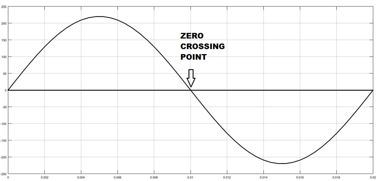
Для управления напряжением переменного тока первое, что мы должны уметь делать – это обнаруживать переходы через ноль сигнала переменного тока. Следовательно, в каждый момент времени, когда этот сигнал переходит через ноль, мы должны переключать симистор. Момент перехода через ноль сигнала переменного тока показан на следующем рисунке.

Принцип работы симистора
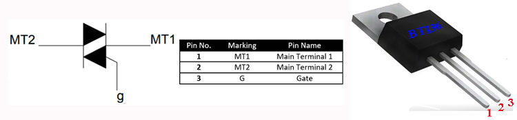
Симистор (симметричный триодный тиристор, в англ. TRIAC) представляет собой переключатель переменного тока с тремя выводами, который можно переключить при помощи подачи отпирающего импульса на его управляющий вывод (затвор). Но в отличие от других подобных переключателей, которые проводят ток в одном направлении, симистор может управлять током в обоих направлениях. В нашем проекте мы будем использовать симистор BT136.
Принцип управления симистора переменным током показан на следующем рисунке.
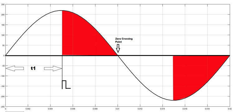
Как показано на рисунке, мы можем переключать, к примеру, симистор на угле 90 градусов при помощи подачи отпирающего импульса на его управляющий вывод. В этом случае мы будем подавать ток на лампу только в половине времени положительной полуволны сигнала (на графике время t1), соответственно, лампа будет гореть вполовину мощности. Уменьшая или увеличивая это время мы можем заставить лампу гореть ярче или тусклее.
Частота сигнала переменного тока в нашей сети составляет 50 Гц, соответственно, период сигнала равен 1/f =20 миллисекунд. Значит, половина периода будет равна 10 мс. Поэтому мы можем изменять время t1 на приведенном графике для управления яркостью свечения лампы переменного тока в диапазоне от 0 до 10 мс (10000 мкс).
Оптопара

Оптопару (оптрон) также называют оптоизолятором. Она используется для изоляции друг от друга двух электрических цепей постоянного или переменного тока. Принцип ее действия достаточно прост: светодиод внутри нее излучает инфракрасный свет, а фотодатчик обнаруживает его. В нашем проекте мы будем использовать оптопару MOC3021 для управления лампой переменного тока, с помощью платы Arduino, использующей сигналы постоянного тока.
Схема проекта
Схема регулятора силы света (диммера) на Arduino и симисторе представлена на следующем рисунке.
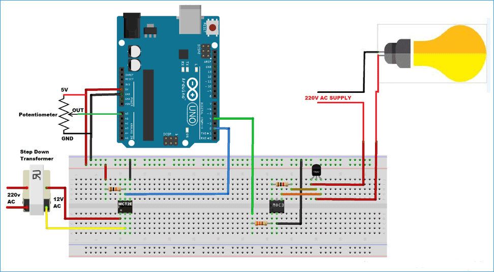
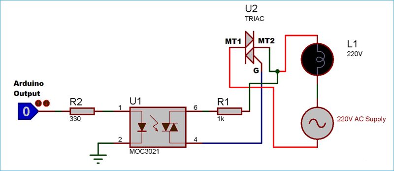
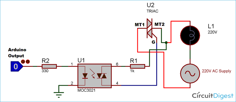
Схема соединения симистора и оптопары показана на следующем рисунке.
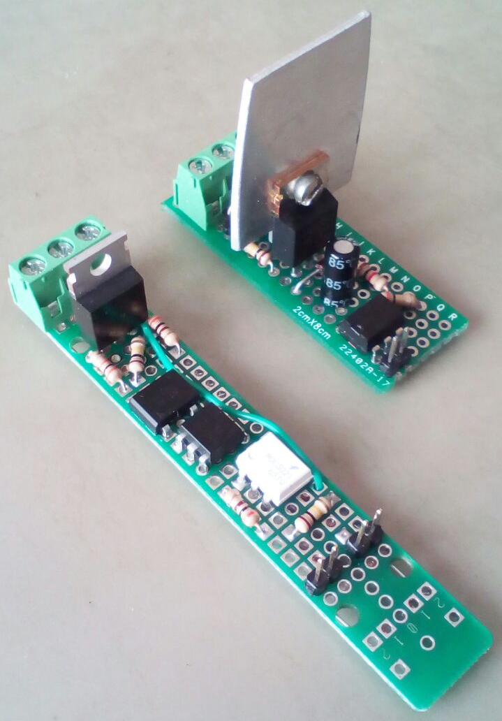
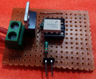
Эту схему мы собрали на перфорированной плате, у нас получилась конструкция следующего вида:

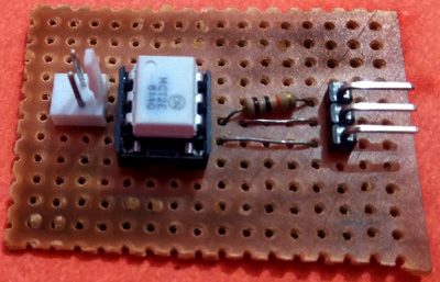
Оптопару MCT2E и соединения с ней мы также разместили на перфорированной плате и подсоединили ее к понижающему трансформатору.

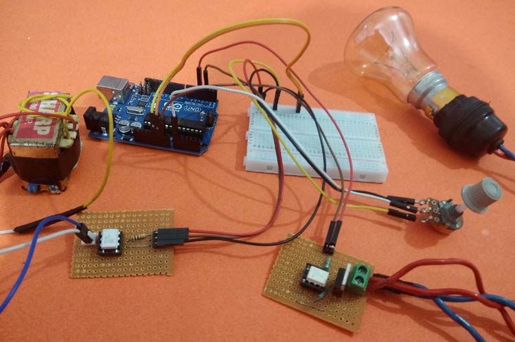
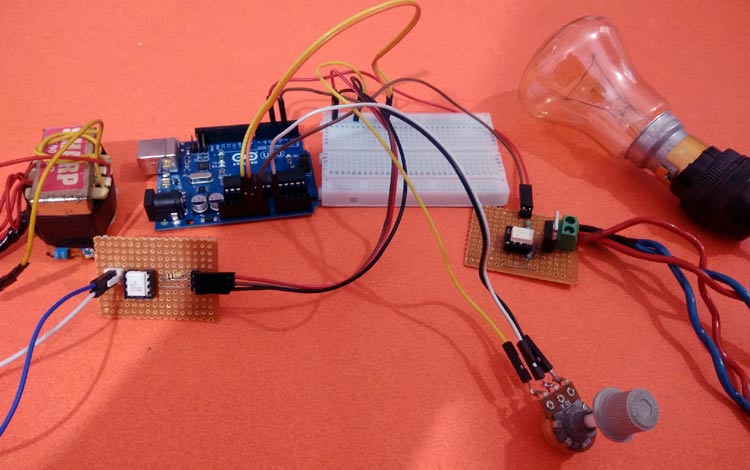
Конструкция всего проекта в сборе выглядит следующим образом:

Объяснение программы для Arduino
Полный код программы и видео, демонстрирующее работу проекта, приведены в конце статьи, здесь же мы кратко рассмотрим основные фрагменты кода.
В самом начале программы нам необходимо объявить используемые глобальные переменные. Симистор у нас подключен к контакту 4 платы Arduino. В переменной dim_val мы будем хранить значение шага диммирования (регулирования силы света), который мы далее будем использовать в программе.
Dimmer
This example shows how to send data from a personal computer to an Arduino board to control the brightness of an LED. The data is sent in individual bytes, each of which ranges in value from 0 to 255. The sketch reads these bytes and uses them to set the brightness of the LED.
You can send bytes to the board from any software that can access the computer serial port. Examples for Processing and Max/MSP version 5 are shown below.
Hardware Required
220 ohm resistor
Software Required
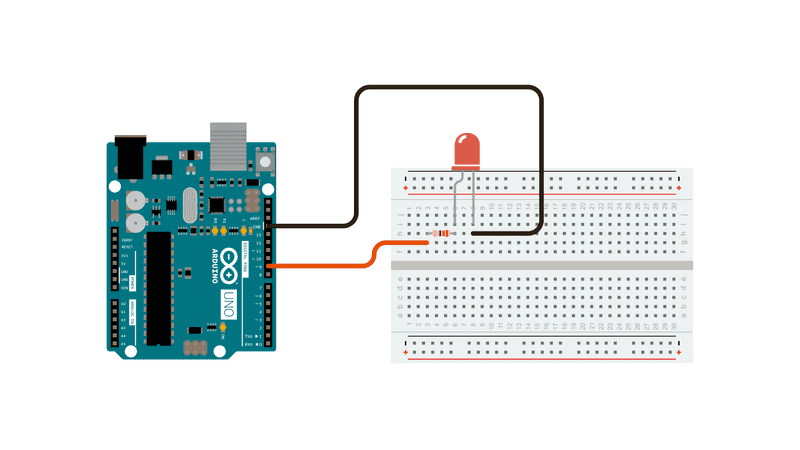
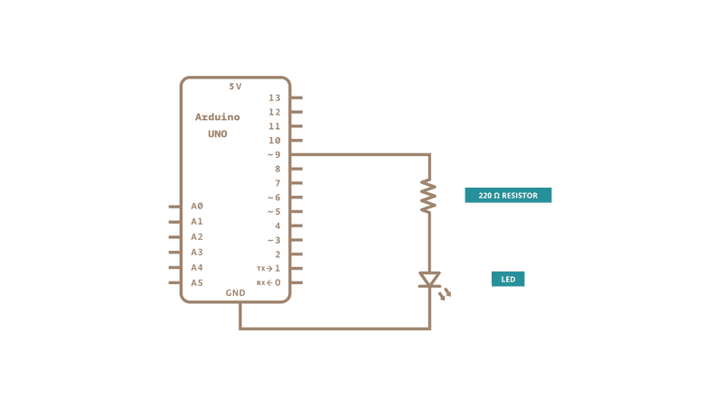
Circuit
Connect the 220 ohm current limiting resistor to digital pin 9, with an LED in series. The long, positive leg (the anode) of the LED should be connected to the output from the resistor, with the shorter, negative leg (the cathode) connected to ground.
Schematic
Processing Code
The Processing sketch in the code sample above will send bytes out the computer serial port to the board to dim the LED.
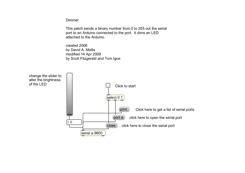
Max code
The Max/MSP patch in the code sample above looks like the image below. Copy it and paste it into a new patch window.
See Also:
ASCIITable — Demonstrates Arduino’s advanced serial output functions.
Graph — Send data to the computer and graph it in Processing.
Midi — Send MIDI note messages serially.
MultiSerialMega — Use two of the serial ports available on the Arduino Mega.
PhysicalPixel — Turn a LED on and off by sending data to your board from Processing or Max/MSP.
ReadASCIIString — Parse a comma-separated string of integers to fade an LED.
SerialCallResponse — Send multiple variables using a call-and-response (handshaking) method.
SerialCallResponseASCII — Send multiple variables using a call-and-response (handshaking) method, and ASCII-encode the values before sending.
SerialEvent — Demonstrates the use of serialEvent().
VirtualColorMixer — Send multiple variables from Arduino to your computer and read them in Processing or Max/MSP.
circuitar/Dimmer
Use Git or checkout with SVN using the web URL.
Work fast with our official CLI. Learn more.
Launching GitHub Desktop
If nothing happens, download GitHub Desktop and try again.
Launching GitHub Desktop
If nothing happens, download GitHub Desktop and try again.
Launching Xcode
If nothing happens, download Xcode and try again.
Launching Visual Studio Code
Your codespace will open once ready.
There was a problem preparing your codespace, please try again.
Latest commit
Git stats
Files
Failed to load latest commit information.
README.rst
Dimmer Library for Arduino
This is an Arduino software library to control AC loads using triacs and a zero cross detector circuit. The library methods can be used to control the AC load power for multiple triacs independently, using a single shared zero-cross circuit.
There are different ways to implement zero cross detector circuits. This library is based on the implementation above, but it can be easily adapted to use any type of zero cross detector circuit.
To install, just click Download ZIP and install it using Sketch > Include Library. > Add .ZIP Library in the Arduino IDE.
The following examples are provided:
- Fade Arduino Fade example using an AC lamp.
- FadeMinimum Arduino Fade example using an AC lamp and setting a minimum power level (useful for dimmable LED or CFL lamps).
- RandomLamps Control 3 dimmable lamps with random values (can be extended to 10 lamps).
- WaveLamps Control 3 dimmable lamps in a wave form (can be extended to 10 lamps).
- CountMode Control high, low response AC loads without introducing noise using count mode.
Copyright (c) 2015 Circuitar All rights reserved.
This software is released under an MIT license. See the attached LICENSE file for details.
About
Arduino library to control dimmable lamps and other AC loads (110V / 220V).
AC Light Dimmer using Arduino and TRIAC
In our household, most of the appliances are powered from the AC supply such as Lights, TVs, and Fans, etc. We can turn ON/OFF them digitally if needed, using Arduino and Relays by building a Home automation setup. But what if we need to control the power of those devices for example to dim the AC Lamp or to Control the speed of the Fan. In that case, we have to use phase control technique and static switches like TRIAC to control the phase of AC supply voltage.
So in this tutorial, we will learn about an AC lamp dimmer using Arduino and TRIAC. Here a TRIAC is used to switch the AC lamp, as this is a Power electronic fast switching device which is the best suited for these applications. Let’s follow the complete article for the hardware details and programming of this project. Also, check our previous tutorials on Light Dimming:
Components Used:
- Arduino UNO-1
- MCT2E optocoupler -1
- MOC3021 optocoupler -1
- BT136 TRIAC-1
- (12-0)V, 500mA Step down transformer-1
- 1K,10K, 330ohm Resistors
- 10K Potentiometer
- AC Holder with Lamp
- AC wires
- Jumpers
Before going further we will learn about Zero crossing, TRIAC, and optocoupler.
Zero Crossing Detection Technique
To control the AC voltage, the first thing we have to do is, to detect the zero crossing of the AC signal. In India, the frequency of AC signal is 50 HZ and as it is alternating in nature. Hence, every time the signal comes to Zero point, we have to detect that point and after that trigger the TRIAC as per the power requirement. The Zero crossing point of an AC signal is shown below:
TRIAC Working

TRIAC is a three-terminal AC switch which can be triggered by a low energy signal at its gate terminal. In SCRs, it conducts in only one direction, but in the case of TRIAC the power can be controlled at both directions. Here we are using a BT136 TRIAC for AC Lamp dimming purpose.

As shown in the figure above, the TRIAC is triggered at a firing angle of 90 degrees by applying a small gate pulse signal to it. The time “t1” is the delay time which we have to give as per our dimming requirement. For example, in this case as the firing angle is 90 percent, hence the power output will also be halved and hence the lamp will also glow with half intensity.
We know that the frequency of AC signal is 50 Hz here. So the time period will be 1/f, which will be 20ms., so for a half cycle, this will be 10ms or 10,000 microseconds. Hence for controlling the power of our AC lamp, the range of “t1” can be varied from 0-10000 microseconds. Learn more about Triac and its working here.
Optocoupler
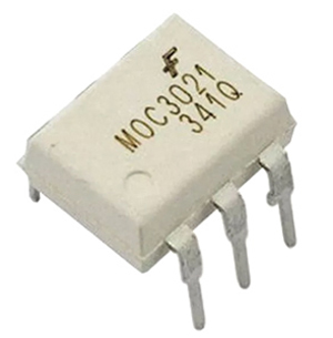
Optocoupler is also known as Optoisolator. It is used to maintain isolation between two electrical circuits like DC and AC signals. Basically, it consists of an LED that emits infrared light and the photosensor which detects it. Here we are used a MOC3021 optocoupler to control the AC lamp from microcontroller signals which is a DC signal. We previously used the same MOC3021 optocoupler in TRIAC dimmer circuit. Also learn more about Optocouplers and its types by following the link.
Circuit Diagram:
Circuit diagram for AC Light Dimmer is given below:
TRIAC and Optocoupler Connection Diagram:
I have soldered a circuit of TRIAC and Optocoupler MOC3021 on a perf board. After soldering it will look like below:
I have also soldered optocoupler MCT2E on perf board for connecting it to Transformer for AC supply:
And the complete circuit for Arduino Lamp Dimmer will look like below:
Programming Arduino for AC Light Dimmer:
After successful completion of hardware setup, now its time to program the Arduino. The complete program with a demo video is given at the end. Here we have explained the code stepwise for better understating.
In the first step, declare all the global variables, which are going to use throughout the code. Here the TRIAC is connected to pin 4 of Arduino. Then the dim_val is declared to store the value of the dimming step which we will use in the program.
Next, inside setup function declare the LAMP pin as output and next configure an interrupt to detect the zero crossing. Here we have used a function called attachInterrupt, which will configure digital Pin 2 of Arduino as external interrupt and it will call the function named zero_cross, when it detects any interrupts at its pin.
Inside infinite loop, read the analog value from potentiometer which is connected at A0. Then map it to a value range of (10-49). To find out this we have to do a small calculation. Earlier I have told that, each half cycle is equivalent to 10,000 microseconds. So, let we need to control the dimming in 50 steps (which is an arbitrary value. You can also change it). I have taken the minimum step as 10, not Zero, because 0-9 steps give approximately the same power output and it is not recommended practically to take the maximum step number. So, I have taken the maximum step as 49.
Then each step time can be calculated as 10000/50= 200 microseconds. This will be used in the next part of the code.
In the final step, configure the interrupt-driven function zero_cross. Here the dimming time can be calculated by multiplying the individual step time with no. of steps. Then after this delay time, the TRIAC can be triggered using a small high pulse of 10 microseconds which is sufficient to turning on a TRIAC.
Working of Arduino Lamp Dimmer Circuit
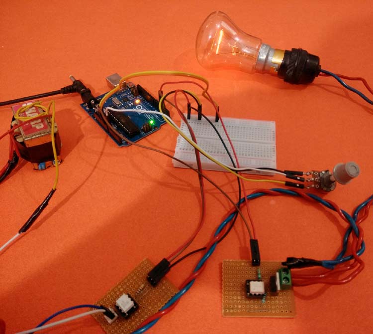
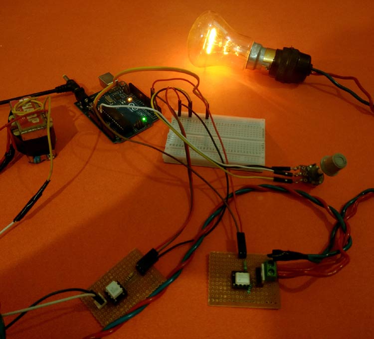
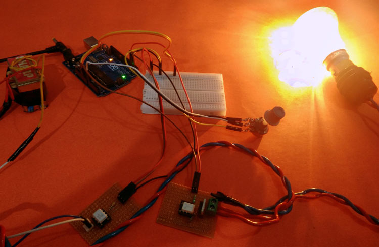
Below are the pictures of showing three stages of dimming the AC bulb using Arduino and TRIAC.
1. Low dimming step
2. Medium Dimming step
3. Maximum Dimming step:
This is how an AC Light Dimmer circuit can be built easily using TRIAC and optocoupler. A Working Video and Arduino Light Dimmer Code is given below
attachInterrupt(digitalPinToInterrupt(2), zero_cross, CHANGE);