Сенсоры с аналоговым сигналом
При использовании аналогового сигнала, показания датчика передаются в виде переменного напряжения на сигнальном проводе. Сигнальное напряжение может принимать значение от 0 В до напряжения питания. Хотя обычно «рабочий диапазон» напряжений более узкий.
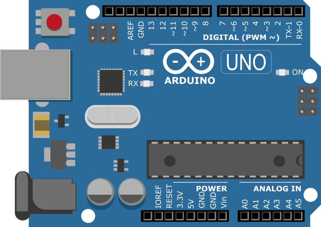
На Arduino Uno имеется 6 аналоговых входов с помощью которых можно считывать переменное напряжение, и исходя из его значения получать значения с датчика. Эти входы объединены на плате в группу «Analog In» и пронумерованы от A0 до A5.
Протокол
Между измеряемой величиной и возвращаемым обратно напряжением установлена определённая зависимость. Например: чем больше величина, тем больше напряжение; или наоборот: чем больше величина, тем напряжение меньше. Иногда зависимость более сложная: напряжение растёт до определённого значения, затем падает пропорционально ему. Всё зависит от сенсора.
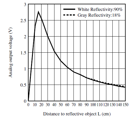
Так например, инфракрасный дальномер измеряет расстояние до объекта перед ним. Для него чем меньше расстояние, тем больше напряжение. Если объект находится на расстоянии 20 см, сенсор выдаёт
2,5 В на сигнальном проводе; на расстоянии 60 см
1 В; на расстоянии 150 см
0,4 В. Точная диаграмма зависимости напряжения от расстояния для инфракрасного дальномера от Sharp приведена в его datasheet’е.
Для других сенсоров диаграммы можно так же найти в документации или получить экспериментально.
Программирование
Считать данные с аналогового сенсора крайне просто. Для этого в Arduino существует стандартная функция analogRead. Так, например, если вы подключили сенсор к контакту A5, чтобы получить показания сенсора в переменную value достаточно исполнить:
Диапазон входного напряжения от 0 до 5 В в программе проецируется на диапазон целочисленных значений от 0 до 1023. Перевести полученное значение в физические единицы, такие как, например, расстояние, поможет функция map. Подробнее об этом рассказывает Джереми Блюм, в своём 4-м видеоуроке по Arduino.
Таким образом, программа, которая раз в секунду считывает показания аналогового сенсора, подключенного к контакту А5, и посылает их на компьютер может выглядеть так:
Преимущества и недостатки аналогового сигнала
Преимуществом сенсоров с аналоговым сигналом является крайняя простота их использования с Arduino. Кроме того, поскольку показания датчика можно считывать «из коробки» всего одной командой, драгоценные килобайты памяти на микроконтроллере не расходуются на хранение алгоритма расшифровки протокола, присущего цифровым сенсорам.
Главным недостатком аналогового сигнала является неустойчивость к внешним шумам. Если провод от сенсора до микроконтроллера будет достаточно длинным, он начнёт работать как антенна и улавливать внешние электромагнитные поля: провод сам будет влиять на выходное напряжение и тем самым искажать показания. Поэтому разумный предел длины провода для аналогового сенсора — не более 50 см.
Чтобы уменьшить влияние помех на полезный сигнал можно воспользоваться усреднением. Так как помехи носят случайный характер, они будут влиять на полезный сигнал тем меньше, чем больше выборок используется для усреднения. С усреднением наш пример будет выглядеть так:
Аналоговый сигнал при чтении на Arduino может иметь максимум 1024 градации. С учётом того, что рабочий диапазон почти всегда уже допустимого, полезных градаций ещё меньше. Этого может оказаться недостаточно для высокоточных измерений.
На ATmega328p, установленном на Arduino, как и на большинстве других микроконтроллеров аналоговых входов немного. Поэтому количество одновременно контролируемых аналоговых сенсоров ограничено. У Arduino Uno их 6, у Mega 2560 — 16.
Если какой-либо из недостатков существенен для вашего проекта, обратите внимание на цифровые сенсоры.
Types of Arduino Sensors | How does Sensor work?

Arduino Sensors | Types of Arduino Sensors
In this post of the “Robotics for Beginners Series”, I will explain everything you need to know about sensors – Different types of sensors, connecting sensors to Arduino and its application in DIY hobby projects for you to get started with your own Robot.
How to Make a Robot for Kids?
This is the second part of Robotics for Beginners Series. This series is for people especially beginners and kids who are getting started with robotics; nice and easy robotics for beginners tutorial. In this series, we will guide you through the basic of ‘Robotics for Beginners’ and you will learn how to how to Make a Robot for Kids easily.
In the previous lesson – Robotics for Beginners series we explained what robot is, what are the different parts of Robots and how you can make a beginner-friendly Robot. Check it out if you haven’t seen that yet.
Like the previous post, I will try to make this post as interesting and simple as possible so that everyone can understand everything easily in a fun way. Let’s get started with a Simple Question
What is a sensor?
Basically, sensors are specially designed devices or objects that will detect the properties, events, or changes in the environment, and then provide a corresponding signal. They are one of the crucial instruments which will bridge the physical and electronic world.
Here are some of the sensors that we commonly use in everyday projects. We have IR sensors, which will sense infrared rays, ultrasonic sensors to sense ultrasonic sound, heat sensors to sense temperature, a pressure sensor to sense touch/pressure and there are so much more.
How does a sensor work?
All the sensors will have an Input and an Output.
The input will be the physical quantity we will be measuring and the output will be the change in electrical property of the sensor element. Sensors react to changing physical quantity by altering their electrical properties.
For e.g. A photodiode is a sensor that would change its resistance with respect to the ambient light. This change in resistance can be detected by the circuit or the microcontroller by a proportional change in voltage where it is connected.
What is a Sensor Module?
In some cases, the output will be very low, so the sensor element alone might not be sufficient to analyze the obtained signal. In such cases, a signal conditioning circuit is required in order to amplify and filter the signal produced by the sensor element in the desired range with respect to the microcontroller or the end device that we use. So the sensor element and the conditioning circuit are together known as the Sensor Module.
For example, in the case of a microphone, it detects the audio signal and converts to the output voltage which will be in terms of millivolts. This voltage is not enough to drive a circuit. So an amplifier will be used to increase the signal strength before using it in circuits like clap switches.
Types of Arduino Sensors
Based on the type of Output Signal, there are mainly two types of sensors – Digital and Analog Sensors.
Digital Sensors
Digital Sensors could be as simple as an on/off sensor. Either there is light or not. 1 or 0. True or False. Sometimes, they have a serial digital output which includes UART, or I2C, or SPI.
But the world is not just 0s and 1s is it? What if you want to measure ambient light using LDR or temperature using a temperature sensor? How do we take analog sensor readings?
Analog Sensors
Analog Sensor is simple. It has a voltage output that can vary with respect to the external physical quantity. This way, you can measure the correct value of light and not just black or white.

Looks like you are enjoying our site.
Let us give you more that you might be interested in.
You got it! Stay tuned for more.
Typically the analog voltages are input to a microcontroller like the Arduino via the analog input pins. Things like temperature changes would be portrayed as a proportional change in the resistance of a thermistor.
Digital Sensors with Serial Out
Within the category of digital sensors, there is another set of sensor modules, whose output is available in the form of data transmitted via certain serial protocols like UART or I2C or SPI.
Such sensors are interfaced to the communication channels to receive data using the microcontroller.
Connecting Sensors to Arduino
We have now measured the physical quantity and converted it to its electrical equivalent. All we need to do is read it with the help of Arduino and do something useful.
GPIO Pins
Arduino has several digital Input/Output pins, generally known as GPIO pins or General Purpose Input Output Pins that are designed either to provide input to the processor or get output from the processor. We will be making use of these pins to read the data from sensors.
Arduino Digital Read
Microcontrollers in Arduino are capable of detecting binary signals or Digital signals – 0 or 1. That is, for a 5V Arduino board, it understands 0V as a logic 0 and a voltage above 3V as a logic 1.
In most of the boards, almost all the GPIO pins in Arduino can be used as Digital Pins. Which means, it can be used to connect digital output sensors and read digital value
Arduino Analog Read
To measure the value of analog signals, the Arduino has a built-in analog to digital converters or ADC at certain pins. These ADC circuits turn the analog voltage into a digital value that the Arduino can read. These pins are what we call the analog pins. This is where we connect the analog sensor input.
Different boards will be having different numbers of Analog pins. For example, Arduino UNO has 6 analog pins A0-A5. Let me know how many analog pins you have on your Arduino board. Simply comment on the board name and the number of pins.
From these sensor outputs, we can write conditions in your Arduino code and upload it to your Arduino board and do fun stuff like turning on a bulb when ambient light is low or making an autonomous robot like a line follower which will sense its path using IR sensor and follows a line.
Types of Arduino Sensors – Easy to Learn Sensors
I have a list of sensors that are beginner-friendly, easy to get started with, and very easy to hook up with Arduino and learn its working. So if you want, click on the link and check it out. Let me know in the comments if I missed any beginner-friendly sensors.
Arduino Sensors
Easy to learn Sensors for you to get Started With Arduino
Application of Sensor in DIY Robot – Example
Now, as usual, an example! Consider this line follower robot using Arduino. This robot uses IR sensors to detect the track and use motors to move around depending upon the color of the track.
How does an IR Sensor work?
Here IR sensor is the Sensor that senses the environment and gathers input. IR sensor mainly consists of an IR transmitter (IR LED) and an IR receiver (Usually a photodiode). IR LED always emits IR rays to the direction it is pointing to.
Now let us bring it closer to a surface. When the IR rays hit a surface, some rays will be reflected back depending upon the color of the surface.
Means, the brighter the color is, the more IR will be reflected back. Darker the color is, more IR will be absorbed by the surface and lesser IR rays will be reflected back.
These reflected rays are received by the Photodiode and depending upon the intensity of the received IR rays, the resistance of the photodiode varies which will, in turn, vary the output voltage.
Line Follower Simplified
So an IR sensor makes it very easy to measure how bright the surface is, which will make it easy for us to track the line. We will feed these signals to Arduino through GPIO pins and the Arduino controls the motor and decides which way the robot should go.
Using these sensors, the robot senses the path, takes a decision by its own and reacts to its environment by moving only through the black path. That is how a sensor works in a robot!
The most basic autonomous Robot you can build in your home is a line follower. You can make a line follower with or without a microcontroller. So if you are interested, I will share the link in the description.
What’s Next in Robotics for Beginners Series?
In the next video of this series I will explain the muscles of the Robot – The Motors. There we will be focussing on what motor is, different types of motors and how we use them in Robots.
If you are really interested in DIY robotics, check out our channel. you will find lots of fun stuff to make using Arduino and lots of other components. Hit the subscribe button and stay tuned for more awesome videos. See you soon guys.
Analog Input
In this example we use a variable resistor (a potentiometer or a photoresistor), we read its value using one analog input of an Arduino board and we change the blink rate of the built-in LED accordingly. The resistor’s analog value is read as a voltage because this is how the analog inputs work.
Hardware Required
Potentiometer or
10K ohm photoresistor and 10K ohm resistor
built-in LED on pin 13 or
220 ohm resistor and red LED
Circuit
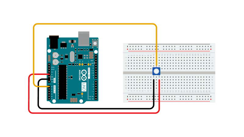
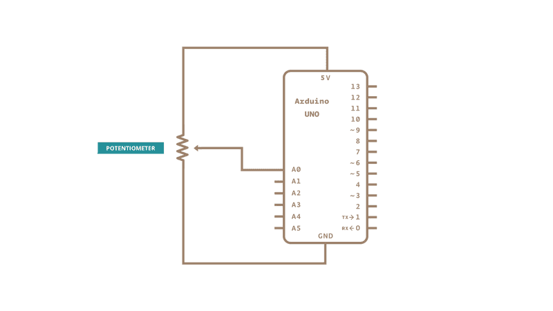
With a potentiometer
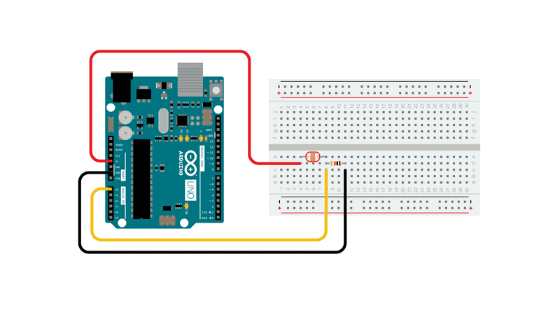
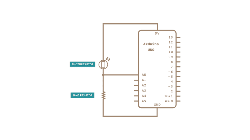
With a photoresistor
Connect three wires to the Arduino board. The first goes to ground from one of the outer pins of the potentiometer. The second goes from 5 volts to the other outer pin of the potentiometer. The third goes from analog input 0 to the middle pin of the potentiometer.
For this example, it is possible to use the board’s built in LED attached to pin 13. To use an additional LED, attach its longer leg (the positive leg, or anode), to digital pin 13 in series with the 220 ohm resistor, and it’s shorter leg (the negative leg, or cathode) to the ground (GND) pin next to pin 13.
The circuit based on a photoresistor uses a resistor divider to allow the high impedence Analog input to measure the voltage. These inputs do not draw almost any current, therefore by Ohm’s law the voltage measured on the other end of a resistor connected to 5V is always 5V, regardless the resistor’s value. To get a voltage proportional to the photoresistor value, a resistor divider is necessary. This circuit uses a variable resistor, a fixed resistor and the measurement point is in the middle of the resistors. The voltage measured (Vout) follows this formula:
Vout=Vin*(R2/(R1+R2))
where Vin is 5V, R2 is 10k ohm and R1 is the photoresistor value that ranges from 1M ohm in darkness to 10k ohm in daylight (10 lumen) and less than 1k ohm in bright light or sunlight (>100 lumen).
Schematic
At the beginning of this sketch, the variable sensorPin is set to to analog pin 0, where your potentiometer is attached, and ledPin is set to digital pin 13. You’ll also create another variable, sensorValue to store the values read from your sensor.
The analogRead() command converts the input voltage range, 0 to 5 volts, to a digital value between 0 and 1023. This is done by a circuit inside the microcontroller called an analog-to-digital converter or ADC.
By turning the shaft of the potentiometer, you change the amount of resistance on either side of the center pin (or wiper) of the potentiometer. This changes the relative resistances between the center pin and the two outside pins, giving you a different voltage at the analog input. When the shaft is turned all the way in one direction, there is no resistance between the center pin and the pin connected to ground. The voltage at the center pin then is 0 volts, and analogRead() returns 0. When the shaft is turned all the way in the other direction, there is no resistance between the center pin and the pin connected to +5 volts. The voltage at the center pin then is 5 volts, and analogRead() returns 1023. In between, analogRead() returns a number between 0 and 1023 that is proportional to the amount of voltage being applied to the pin.
That value, stored in sensorValue , is used to set a delay() for your blink cycle. The higher the value, the longer the cycle, the smaller the value, the shorter the cycle. The value is read at the beginning of the cycle, therefore the on/off time is always equal.
See Also:
AnalogInOutSerial — Read an analog input pin, map the result, and then use that data to dim or brighten an LED.
AnalogWriteMega — Fade 12 LEDs on and off, one by one, using an Arduino Mega board.
Calibration — Define a maximum and minimum for expected analog sensor values.
Fading — Use an analog output (PWM pin) to fade an LED.
Smoothing — Smooth multiple readings of an analog input.