Analog Devices Wiki
Table of Contents
Interfacing SigmaDSP Processors with a Microcontroller
Overview
This guide describes how to integrate a SigmaDSP processor into microcontroller-based systems.
Microcontrollers are available in a wide variety of architectures and capabilities, so rather than creating a fully-featured SigmaDSP library for every processor, we focus here on the principles behind successful SigmaDSP integration so that users can complete designs quickly and efficiently.
Arduino-compatible example code, attached below includes a simple program to boot ADAU1701, ADAU1761, or ADAU1467 processors without any modification. It is written for the Teensy 4.0, so pin assignments should be adjusted for use on other platforms. Teensy 4.0 was chosen because it is easy to use and has enough memory to store even the largest SigmaDSP program. Version 1.1.0 of the code is also tested and working on ESP8266 (with minor changes described below).
This guide takes advantage of C++ header files generated by SigmaStudio which reduce complexity in users’ code.
Notes about Example Code Version 1.1.0
Communications- I2C and SPI
Hardware Connections
USBi Connector
All SigmaDSP evaluation boards are outfitted with a 10-pin connector for programming. The connector mates with a USBi programmer (included with all evaluation boards) using the pinout shown here. The USBi connector is also the best way to connect a microcontroller to your evaluation board.
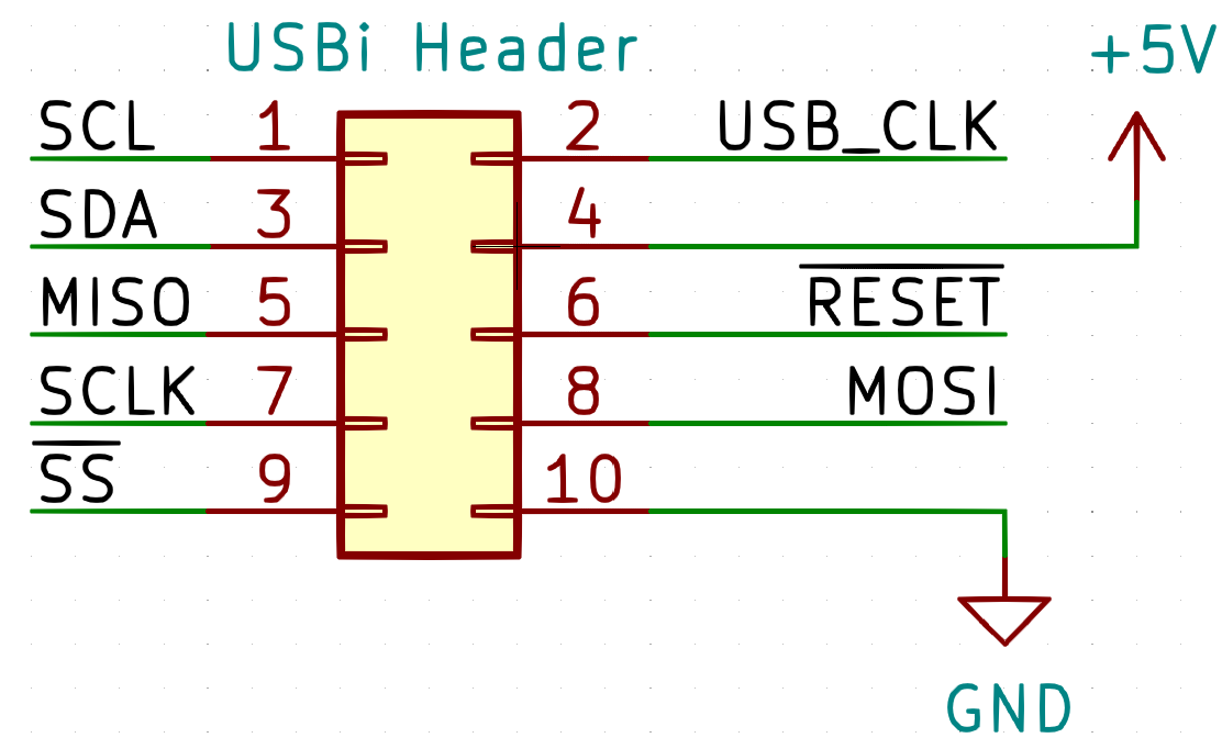
Please reference the schematics for your evaluation board’s User Guide, which can be found on its product webpage, to determine which interfaces are exposed on connectors. Also note whether your evaluation board includes pull-up resistors on the SCL, SDA, and /SS pins; if they are not present, you must add them.
ADAU1701
The evaluation board uses 3.3V logic levels. Level shifters are recommended for interfacing with 1.8V or 5V microcontrollers.
The 5V power pin (Pin 4) can be connected to your microcontroller’s VUSB pin if sufficient current is available. Be careful not to exceed 500mA total current draw from a USB port.

ADAU1761
EVAL-ADAU1761Z also allows Pin 4 of the USBi connector to power the DSP . Again, ensure that your system consumes port.

ADAU145x/ADAU146x
Note that Pin 4 of the USBi connector illuminates an LED but does not supply power to the entire board. ADAU145x and ADAU146x processors should be powered through the barrel jack.

Example Schematic
The following schematic based on the Teensy 4.0 microcontroller allows programming of SigmaDSP processors through the USBi programming header and was used for development of the example code. Please click the image to see a full-resolution version.

Notice that the SCL and SDA connections are duplicated on the header:
The same is true for the microcontroller:
Considerations for Self Boot
Microcontroller memory is often in short supply. By configuring the SigmaDSP processor to self boot from an external EEPROM, most of the SigmaDSP program can be excluded from your microcontroller code. However, there are some considerations and common pitfalls to take into account before making this decision:
Navigating the Example Code
Overview of Included Files
The example code is separated into the following files:
The example code requires some files exported by SigmaStudio which describe the contents of the SigmaStudio project, including register values and parameter locations.
Most applications do not require these files to be altered.
SigmaStudio also exports the following files which are not used by the example code.
Example Code Change Log
Page Tools
Analog Devices Uses Cookies for Enhanced Online Performance
Some cookies are required for secure log-ins but others are optional for functional activities. Our data collection is used to improve our products and services. We recommend you accept our cookies to ensure you’re receiving the best performance and functionality our site can provide. For additional information you may view the cookie details. Read more about our privacy policy.
The cookies we use can be categorized as follows:
Strictly Necessary Cookies: These are cookies that are required for the operation of analog.com or specific functionality offered. They either serve the sole purpose of carrying out network transmissions or are strictly necessary to provide an online service explicitly requested by you. Analytics/Performance Cookies: These cookies allow us to carry out web analytics or other forms of audience measuring such as recognizing and counting the number of visitors and seeing how visitors move around our website. This helps us to improve the way the website works, for example, by ensuring that users are easily finding what they are looking for. Functionality Cookies: These cookies are used to recognize you when you return to our website. This enables us to personalize our content for you, greet you by name and remember your preferences (for example, your choice of language or region). Loss of the information in these cookies may make our services less functional, but would not prevent the website from working. Targeting/Profiling Cookies: These cookies record your visit to our website and/or your use of the services, the pages you have visited and the links you have followed. We will use this information to make the website and the advertising displayed on it more relevant to your interests. We may also share this information with third parties for this purpose. Decline cookies
©1995 — 2022 Analog Devices, Inc. All Rights Reserved
MCUdude/SigmaDSP
Use Git or checkout with SVN using the web URL.
Work fast with our official CLI. Learn more.
Launching GitHub Desktop
If nothing happens, download GitHub Desktop and try again.
Launching GitHub Desktop
If nothing happens, download GitHub Desktop and try again.
Launching Xcode
If nothing happens, download Xcode and try again.
Launching Visual Studio Code
Your codespace will open once ready.
There was a problem preparing your codespace, please try again.
Latest commit
Git stats
Files
Failed to load latest commit information.
README.md
SigmaDSP is an intuitive library used for controlling an Analog Devices Sigma DSP over i2c using an Arduino or an Arduino compatible board.
Table of contents
What is SigmaDSP and why do we need a library for it?
SigmaDSP is a product lineup of programble DSPs for audio use by Analog Devices Inc. SigmaDSPs are known for their easy to use programming environment SigmaStudio, where the firmware is built in a graphical enviroment where you add «blocks» or «modules» to the program flow. Such blocks may be volume sliders, EQs, signal generators and so on. This is great if you want to get started quickly, but sadly Analog Devices have not focused on how to control these module parameters from external devices. Some of the «modules» are even based on closed source alorithms and will (most likely) never be possible to control outside of SigmaStudio.
On the other side many of the modules are fairly easy to reverse engineer, and control of these can therefore be implemented in a library like this. Thanks the enourmous effort the AidaDSP team have put into this reverse engineering. This library would have existed if it weren’t for them.
Only the ADAU1701, ADAU1702 and ADAU1401 are supported.
Exporting a SigmaStudio project for use with the SigmaDSP library
Even though Analog Devices haven’t focused much on external control over i2c it is possible to export the SigmaStudio project. This result in a bunch of header files where important data and parameter macros are spread across these files. This makes it a pain to keep track of everything.
To solve this issue I’ve created a script that extract the necessary information in these files and formats it into a single header file that can be used with this library. I call this script DSP_parameter_generator. Windows users may use the PowerShell version (DSP_parameter_generator.ps1), while Mac and Linux users may use the shell version (DSP_parameter_generator.sh).
The parameter generator script
First let’s talk about what this script expects in order to function properly. The SigmaDSP does not contain a non-volatile memory, so the entire program must be loaded into RAM on boot. If the DSP is power cycled or gets reset, the program must be loaded again. This loading can be done in two ways and this library support both. See the examples on how this may be implemented.
- The first option is to store the entire DSP program in the microcontroller flash memory. The microcontroller will have to load the program over i2c when the DSP is powered or resat.
- The other option is to use an external i2c EEPROM memory such as the 24C64. SigmaDSPs are able to load frimware from an external i2c EEPROM into RAM on the condition that the EEPROM i2c address is known and the physical SELFBOOT pin on the DSP is tied high.
There are some rules you need to follow in order for the script to work as intended:
- The DSP in the SigmaStudio project must be called IC 1
- The i2c EEPROM in the SigmaStudio project (if present) must be called IC 2
- DO NOT edit any of the exported files. The script depends on lines and spaces from the exported files. Editing any of the files may cause the script to malfunction.
Exporting a SigmaStudio project
This guide assumes you created your project based on the 0_Template project file, which is a blank project with a few pre-configured settings.
- Start out by adding all the blocks you want in your project
- Locate your SigmaStudio project folder. Open this and create a folder called export
- (Skip this step if not using EEPROM) Open the Hardware configuration tab and add an external EEPROM device by draging the E2PROM symbol into the work space and connect it to USBi’s second wire connector. Make sure the EEPROM size and address matches the actual address of the EEPROM. The EEPROM module has to be named IC_2!
- Compile the project by clicking the Link Compile Download button

- Click the diskette icon and store the files in the export folder you just created

- In the Hardware Configuration tab, right click on the SigmaDSP (called IC_1) and select the option «Write Latest Compilation to EEPROM. Don’t worry if you get any connection error messages, we’re only looking for the generated files.
- Open the project folder again and move the subfolder called [project name]_IC_2 into export.
- Copy the script (DSP_parameter_generator.ps1 or .sh) into the Arduino project folder
Now the project files are ready to be handled by the DSP parameter generator script. Continue reading for more information on how this is done.
Executing the parameter generator script
As already mentioned, this script has to be placed in the Arduino project folder. It will search for exported project files in the same folder or in any subdirectory. A recommended folder structure for your Arduino project looks something like this:
Windows users may use the DSP_parameter_generator.ps1 PowerShell script. Simply double click the DSP_parameter_generator.ps1 file and it will output a header file in the same directory as the script is located. If you’re not able to execute the scrit it may be because you’ll have to enable execution of unsigned Powershell scripts. You can do this by seaching for Powershell, right clicking on it and select «Run as administrator». Then paste and run the following line:
set-executionpolicy remotesigned
Close the PowerShell window. You should now be able to run the script by double clicking it.
*NIX users may use the DSP_parameter_generator.sh script, which is built using bash and awk. Simply double click the DSP_parameter_generator.h file and it will output a header file in the same directory as the script is located. If you can’t execute the script it may be because the file itself isn’t executable. Open your terminal, cd into the directory where the script is located. Paste and run the following line:
chmod +x DSP_parameter_generator.sh
Close the terminal window. You should now be able to run the script by double clicking it.
About
A versatile Arduino library for interfacing with the ADAU1401, ADAU1701 and ADAU1702 audio DSPs
5. The microprocessor: how to control the DSP
The term “microprocessor” covers a broad range of programmable devices that can perform arithmetic and logical operations. We are going to focus on the category sometimes called microcontrollers, which typically use 8-bit computing cores and include peripherals such as timers, input/output ports, analog inputs and serial communications. This is not a small boutique category, as annual unit sales of microcontrollers are in the 20 billion range. These devices are used to control washing machines, microwave ovens, TV’s, children’s toys, and a wide range of small electronic devices. A modern automobile will have on the order of 10 to 100 microcontrollers, for the entertainment system, engine/transmission control, lighting control, to airbag control.
As you might expect with sales of 20 billion a year, there are many ways to develop the code for these devices, and some are a lot easier than others. Also, there is a wide range of capabilities to choose from. The average selling price of a microcontroller in large quantities is around 70 to 80 cents so this large volume includes some fairly simple low-cost controllers. We are going to focus on the microcontrollers that are fairly easy to work with but that offer good speed and a lot of capability. These include devices that are in the 5 to 100 millions of instructions per second range. Controlling a DSP chip is a complicated task, so we are going to need that processing power.
Arduino
The Arduino initiative has deep roots in creative efforts to control devices for artists and designers. But it is also well grounded in traditional C language programming. As a result, it offers both ease of use and a professional, disciplined code development capability. One of the key features of Arduino is the open-source hardware based on very capable microprocessors. The first generation of Arduino devices were based on the capable 8-bit AVR processor cores from Atmel. More recent releases are using the 32-bit ARM devices–the same series that is powering the current generation of cell phones. This combination of user-friendly code development, low cost open source hardware and an upgrade path that supports floating point computing is very attractive.
But the most important benefit of using the Arduino devices is the great open source software development initiative. Individual developers are writing code to interface to a number of devices such as remote controls, LCD displays, and interesting new products such as “smart” RGB displays and DSP chips. We will leverage some of those code libraries for a later case study.
Getting Started
The Arduino website at www.arduino.cc has frequent updates to the development environment and has numerous tutorials and examples. You can buy an Arduino board at Microcenter for $5.99 and connect some LED’s and build yourself a blinking t-shirt if you want to start out with a simple flashy example. Arduino boards are also available online from Sparkfun, Adafruit and many other vendors, or you can order directly from www.arduino.cc. If you aren’t familiar with programming, it might take a while to get oriented, but once you master a few examples things start making sense.
Code Example #1: I2C Write to the ADAU1701
Let’s jump in with a relatively complicated example–controlling the I2C communications with the ADAU1701. This is probably the most complicated example we could have picked for the ADAU1701, because it requires extending an existing library and understanding some complicated details of how the ADAU1701 memory is organized. If you follow this example, the rest of the code in the DSP test bed should be “easy” by comparison.
If you looked at the Sparkfun tutorial on I2C, you will see a fairly simple example where the device address gets sent, followed by multiple data bytes. That sequence is illustrated in the graphic below.
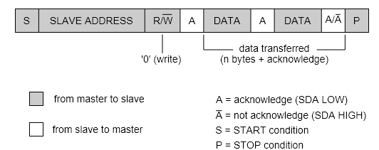
The slave address field is a 7-bit value that is different for each DSP device. Vendors who license the I2C bus are assigned address ranges for their devices, and the ADAU1701 is 00110100, or 0x34.
There is a built-in library called Wire that makes simple I2C communication fairly easy. You don’t need to know how the data gets formatted into the I2C sequence shown above–you just need to call some high-level functions with the data you want to send. You can add the directive to use that library by selecting “Sketch” from the Arduino IDE menu and selecting Wire from the Library menu items, which will generate the following code:
For the type of communication in the example, you can use the Wire functions to specify the device I2C address and send the data. The code for this simple case would look like the example below. The various methods for the Wire routine might look cryptic, but just do a Google search on “Arduino Wire” and you’ll see a list of all of the functions and lots of examples. Note: in the examples below, declarations and directives are in blue text, library calls are in red, and the comments are in green text.
However, the ADAU1701 uses a more complicated variation of the I2C protocol. As we noted in the previous article, the ADAU1701 exposes three memory areas to external devices: Program RAM, Parameter RAM, and Control Registers. Each of these is assigned a separate address range as follows:
According to the ADAU1701 data sheet, the address location is sent right after the device address (it is referred to as a “subaddress”:

So before sending data on the I2C bus, we must specify the address of the memory location we are trying to change. So let’s make an extension to the Wire routines that allows us to write to the ADAU1701 more easily. We’ll call it I2C_16_write to remind us that we need to send the 16 bits of the subaddress before we send the data. Also, the Parameter RAM data is 32-bits wide, so we will need to send 4 bytes of data whenever we update one of the parameters. For this routine we will assume that the 4 bytes of parameter data has been placed in an array that is called Cmd_Data[]. Our routine will look something like this:
This routine might still look a bit cryptic if you are new to microprocessors. But if it makes sense, you are well on your way to writing code to control the ADAU1701.
A note on number representation
One of the challenges of controlling a DSP chip is knowing how the numeric values are represented. The microprocessor uses integers, bytes, strings, floating point, and so forth, and there is a standardized way of mapping those values to the bits and bytes inside microprocessors. But in general DSP chips use a different format, and not all of the DSP devices use the same format. The ADAU1701 uses a “5.23” format, where there are 5 binary digits to the left of the “binary point” and the remaining 23 bits are the fractional part. The ADAU1452 uses an “8.24” representation, and the ST chips like the STA328 use a pure fractional representation (0.24).
So we need some routines to convert the data to the correct format before sending it to the device on the I2C bus. Once we have these routines, we simply call them before sending the data, and the DSP chip will be happy. Here’s an outline of the steps needed to format a floating point value into the 4 bytes we need to send to the ADAU1701:
This conversion routine is already written and available in the DSP test bed for the ADAU1701, and you simply need to call it before sending the 4 bytes to the DSP. But if you use a different DSP chip, this routine will need to be adjusted accordingly.
Code Example #2: Enable the A/D and DAC’s
This example illustrates how to control the registers for the ADAU1701. This is about as “technical” as it comes, so if you can get through this example, you are probably ready to write your own code to control the ADAU1701.
The ADAU1701 has quite a few registers that control various features inside the device, such as enabling digital audio and selecting which pin it will use for input or output. But the “main” register is the DSP Core Control, which is at address 0x081C. We are going to look at programming this register for one important reason. The ADAU1701 powers up with the A/D and DAC disabled, which ensures that the IC is “quiet” after power is first applied. And if you don’t enable the A/D and DAC by writing to this register, you won’t get any output from the device.
We need to take a look at the ADAU1701 data sheet to understand the DSP Core Control register. Here it is in full glory:

Arrgh–what does this mean? Each bit turns on or off a feature or capability. Lets’s go through them so we understand every single bit. There is more information about each bit in the data sheet. We’ve condensed the description here to make this list a bit shorter. If there is an “(X)” near the pin name, we don’t use that feature in the DSP test bed, so it doesn’t matter whether that bit is set or cleared. RSVD is “reserved”, so we don’t need to worry about that bit, either.
So there are only 4 bits that we need to be concerned about: D4 (ADM), D3 (DAM), D2(CR) and bit 5 (IST).
We aren’t concerned about the IST bit for this example, so let’s just keep that one at “0”. In order to mute the device, we should make bits D4 and D3 a “0”. To enable audio, those bits should be “1”. So if we send a 0000000000011100 to the Core Control Register, we should enable audio. In hexadecimal notation, that is 0x001C. And sending a 0x0014 will turn off the DAC without changing anything else.
So let’s look at the code for two other functions: mute() and unmute(). We will use the same variable declarations as before, and call the I2C_16_write routine to load the data into the ADAU1701:
That’s real working code. If the I2C lines are connected properly and a signal is applied to the input, this code will turn the audio on or off.
Admittedly, this is all rather arcane, but such is the world of DSP chips. But you might be able to appreciate by now that once you have a few code building blocks in place, such as reading and writing on the I2C bus, the rest of the code is a lot easier. And these were “hard” examples. Most of the other code in the DSP test bed is “higher-level” and for the most part is easier to follow.