Arduino.ru
Arduino Uno
Общие сведения
Arduino Uno контроллер построен на ATmega328 (техническое описание, pdf). Платформа имеет 14 цифровых вход/выходов (6 из которых могут использоваться как выходы ШИМ), 6 аналоговых входов, кварцевый генератор 16 МГц, разъем USB, силовой разъем, разъем ICSP и кнопку перезагрузки. Для работы необходимо подключить платформу к компьютеру посредством кабеля USB, либо подать питание при помощи адаптера AC/DC или батареи.
В отличие от всех предыдущих плат, использовавших FTDI USB микроконтроллер для связи по USB, новый Ардуино Uno использует микроконтроллер ATmega8U2 (техническое описание, pdf).
«Uno» переводится как один с итальянского и разработчики тем самым намекают на грядущий выход Arduino 1.0. Новая плата стала флагманом линейки плат Ардуино. Для сравнения с предыдущими версиями можно обратиться к полному списку плат Arduino.
Характеристики
Схема и исходные данные
Питание
Arduino Uno может получать питание через подключение USB или от внешнего источника питания. Источник питания выбирается автоматически.
Внешнее питание (не USB) может подаваться через преобразователь напряжения AC/DC (блок питания) или аккумуляторной батареей. Преобразователь напряжения подключается посредством разъема 2.1 мм с центральным положительным полюсом. Провода от батареи подключаются к выводам Gnd и Vin разъема питания.
Платформа может работать при внешнем питании от 6 В до 20 В. При напряжении питания ниже 7 В, вывод 5V может выдавать менее 5 В, при этом платформа может работать нестабильно. При использовании напряжения выше 12 В регулятор напряжения может перегреться и повредить плату. Рекомендуемый диапазон от 7 В до 12 В.
- VIN. Вход используется для подачи питания от внешнего источника (в отсутствие 5 В от разъема USB или другого регулируемого источника питания). Подача напряжения питания происходит через данный вывод.
- 5V. Регулируемый источник напряжения, используемый для питания микроконтроллера и компонентов на плате. Питание может подаваться от вывода VIN через регулятор напряжения, или от разъема USB, или другого регулируемого источника напряжения 5 В.
- 3V3. Напряжение на выводе 3.3 В генерируемое встроенным регулятором на плате. Максимальное потребление тока 50 мА.
- GND. Выводы заземления.
Память
Микроконтроллер ATmega328 располагает 32 кБ флэш памяти, из которых 0.5 кБ используется для хранения загрузчика, а также 2 кБ ОЗУ (SRAM) и 1 Кб EEPROM.(которая читается и записывается с помощью библиотеки EEPROM).
Входы и Выходы
Каждый из 14 цифровых выводов Uno может настроен как вход или выход, используя функции pinMode(), digitalWrite(), и digitalRead(), . Выводы работают при напряжении 5 В. Каждый вывод имеет нагрузочный резистор (по умолчанию отключен) 20-50 кОм и может пропускать до 40 мА. Некоторые выводы имеют особые функции:
- Последовательная шина: 0 (RX) и 1 (TX). Выводы используются для получения (RX) и передачи (TX) данных TTL. Данные выводы подключены к соответствующим выводам микросхемы последовательной шины ATmega8U2 USB-to-TTL.
- Внешнее прерывание: 2 и 3. Данные выводы могут быть сконфигурированы на вызов прерывания либо на младшем значении, либо на переднем или заднем фронте, или при изменении значения. Подробная информация находится в описании функции attachInterrupt().
- ШИМ: 3, 5, 6, 9, 10, и 11. Любой из выводов обеспечивает ШИМ с разрешением 8 бит при помощи функции analogWrite().
- SPI: 10 (SS), 11 (MOSI), 12 (MISO), 13 (SCK). Посредством данных выводов осуществляется связь SPI, для чего используется библиотека SPI.
- LED: 13. Встроенный светодиод, подключенный к цифровому выводу 13. Если значение на выводе имеет высокий потенциал, то светодиод горит.
На платформе Uno установлены 6 аналоговых входов (обозначенных как A0 .. A5), каждый разрешением 10 бит (т.е. может принимать 1024 различных значения). Стандартно выводы имеют диапазон измерения до 5 В относительно земли, тем не менее имеется возможность изменить верхний предел посредством вывода AREF и функции analogReference(). Некоторые выводы имеют дополнительные функции:
- I2C: 4 (SDA) и 5 (SCL). Посредством выводов осуществляется связь I2C (TWI), для создания которой используется библиотека Wire.
Дополнительная пара выводов платформы:
- AREF. Опорное напряжение для аналоговых входов. Используется с функцией analogReference().
- Reset. Низкий уровень сигнала на выводе перезагружает микроконтроллер. Обычно применяется для подключения кнопки перезагрузки на плате расширения, закрывающей доступ к кнопке на самой плате Arduino.
Обратите внимание на соединение между выводами Arduino и портами ATmega328.
Связь
На платформе Arduino Uno установлено несколько устройств для осуществления связи с компьютером, другими устройствами Arduino или микроконтроллерами. ATmega328 поддерживают последовательный интерфейс UART TTL (5 В), осуществляемый выводами 0 (RX) и 1 (TX). Установленная на плате микросхема ATmega8U2 направляет данный интерфейс через USB, программы на стороне компьютера «общаются» с платой через виртуальный COM порт. Прошивка ATmega8U2 использует стандартные драйвера USB COM, никаких стороних драйверов не требуется, но на Windows для подключения потребуется файл ArduinoUNO.inf. Мониторинг последовательной шины (Serial Monitor) программы Arduino позволяет посылать и получать текстовые данные при подключении к платформе. Светодиоды RX и TX на платформе будут мигать при передаче данных через микросхему FTDI или USB подключение (но не при использовании последовательной передачи через выводы 0 и 1).
Библиотекой SoftwareSerial возможно создать последовательную передачу данных через любой из цифровых выводов Uno.
ATmega328 поддерживает интерфейсы I2C (TWI) и SPI. В Arduino включена библиотека Wire для удобства использования шины I2C.
Программирование
Платформа программируется посредством ПО Arduino. Из меню Tools > Board выбирается «Arduino Uno» (согласно установленному микроконтроллеру). Подробная информация находится в справочнике и инструкциях.
Микроконтроллер ATmega328 поставляется с записанным загрузчиком, облегчающим запись новых программ без использования внешних программаторов. Связь осуществляется оригинальным протоколом STK500.
Имеется возможность не использовать загрузчик и запрограммировать микроконтроллер через выводы ICSP (внутрисхемное программирование). Подробная информация находится в данной инструкции.
Автоматическая (программная) перезагрузка
Uno разработана таким образом, чтобы перед записью нового кода перезагрузка осуществлялась самой программой Arduino на компьютере, а не нажатием кнопки на платформе. Одна из линий DTR микросхемы ATmega8U2, управляющих потоком данных (DTR), подключена к выводу перезагрузки микроконтроллеру ATmega328 через 100 нФ конденсатор. Активация данной линии, т.е. подача сигнала низкого уровня, перезагружает микроконтроллер. Программа Arduino, используя данную функцию, загружает код одним нажатием кнопки Upload в самой среде программирования. Подача сигнала низкого уровня по линии DTR скоординирована с началом записи кода, что сокращает таймаут загрузчика.
Функция имеет еще одно применение. Перезагрузка Uno происходит каждый раз при подключении к программе Arduino на компьютере с ОС Mac X или Linux (через USB). Следующие полсекунды после перезагрузки работает загрузчик. Во время программирования происходит задержка нескольких первых байтов кода во избежание получения платформой некорректных данных (всех, кроме кода новой программы). Если производится разовая отладка скетча, записанного в платформу, или ввод каких-либо других данных при первом запуске, необходимо убедиться, что программа на компьютере ожидает в течение секунды перед передачей данных.
На Uno имеется возможность отключить линию автоматической перезагрузки разрывом соответствующей линии. Контакты микросхем с обоих концов линии могут быть соединены с целью восстановления. Линия маркирована «RESET-EN». Отключить автоматическую перезагрузку также возможно подключив резистор 110 Ом между источником 5 В и данной линией.
Токовая защита разъема USB
В Arduino Uno встроен самовостанавливающийся предохранитель (автомат), защищающий порт USB компьютера от токов короткого замыкания и сверхтоков. Хотя практически все компьютеры имеют подобную защиту, тем не менее, данный предохранитель обеспечивает дополнительный барьер. Предохранитель срабатыват при прохождении тока более 500 мА через USB порт и размыкает цепь до тех пока нормальные значения токов не будут востановлены.
Физические характеристики
Длина и ширина печатной платы Uno составляют 6.9 и 5.3 см соответственно. Разъем USB и силовой разъем выходят за границы данных размеров. Четыре отверстия в плате позволяют закрепить ее на поверхности. Расстояние между цифровыми выводами 7 и 8 равняется 0,4 см, хотя между другими выводами оно составляет 0,25 см.
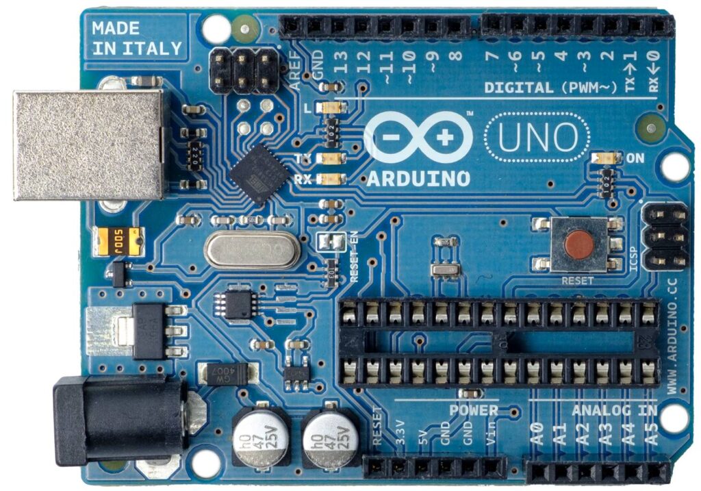
Arduino Uno Board Anatomy
LAST REVISION: 10/05/2022, 01:00 PM
Arduino boards senses the environment by receiving inputs from many sensors, and affects their surroundings by controlling lights, motors, and other actuators. Arduino boards are the microcontroller development platform that will be at the heart of your projects. When making something you will be building the circuits and interfaces for interaction, and telling the microcontroller how to interface with other components. Here the anatomy of Arduino Uno.

-
- Digital pins Use these pins with digitalRead(), digitalWrite(), and analogWrite(). analogWrite() works only on the pins with the PWM symbol.
-
- Pin 13 LED The only actuator built-in to your board. Besides being a handy target for your first blink sketch, this LED is very useful for debugging.
-
- Power LED Indicates that your Arduino is receiving power. Useful for debugging.
-
- ATmega microcontroller The heart of your board.
-
- Analog in Use these pins with analogRead().
-
- GND and 5V pins Use these pins to provide +5V power and ground to your circuits.
-
- Power connector This is how you power your Arduino when it’s not plugged into a USB port for power. Can accept voltages between 7-12V.
-
- TX and RX LEDs These LEDs indicate communication between your Arduino and your computer. Expect them to flicker rapidly during sketch upload as well as during serial communication. Useful for debugging.
-
- USB port Used for powering your Arduino Uno, uploading your sketches to your Arduino, and for communicating with your Arduino sketch (via Serial. println() etc.).
-
- Reset button Resets the ATmega microcontroller.
The text of the Arduino getting started guide is licensed under a Creative Commons Attribution-ShareAlike 3.0 License. Code samples in the guide are released into the public domain.
About arduino uno board
Schematic-o-matic automatically creates KiCAD schematics from your breadboard
Produce pretty patterns with this Arduino-powered project
One board to rule them all: History of the Arduino UNO
As familiar as we all are with the UNO, there’s probably a lot you don’t know about the iconic Arduino microcontroller board. Put on your rose-tinted spectacles, and let’s wax poetic about the origins of this beloved maker board.
Rise of the Techno-Hippies
By 2009, the team that would become Arduino was gathering steam. A team that Make: Magazine once referred to as “designers, teachers, artists, and techno-hippies.”
I don’t think anyone on that team would object to such a definition.
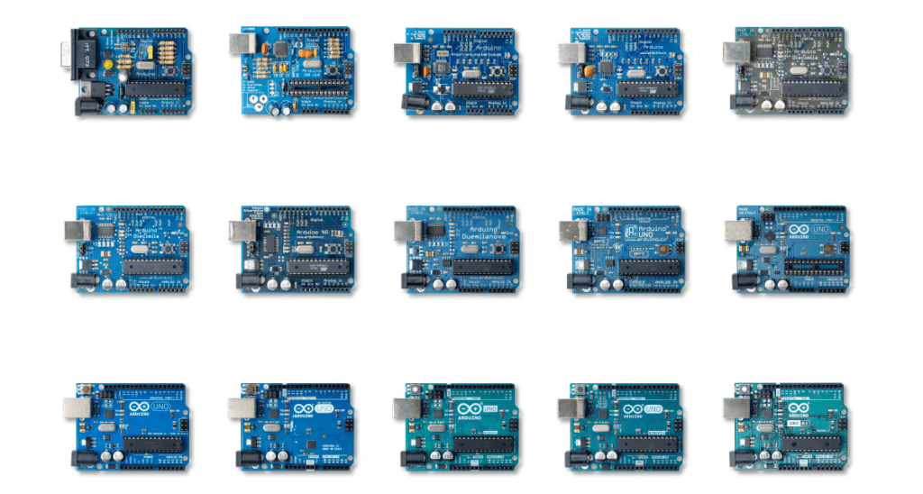
Forged in the crucible of a classroom, the idea of an accessible, affordable electronics development platform was under serious investigation. It would eventually give birth to the Arduino UNO, but despite its name meaning “one,” this is far from Arduino’s first board. Moreover, its name was chosen to mark a point in Arduino’s story where the business itself came out of beta and into version 1.0.
“The UNO is an arrival point of a large number of small experimentations and incremental improvements,” says co-founder Massimo Banzi.
These experiments weren’t just a learning experience for electronics design. They were useability tests, and even marketplace research. Each little quirk, unexpectedly popular feature and, of course, mistake helped to define what makers wanted and needed.
This was a time when the maker movement was still unrepresented by a defining brand or killer product. But not for long.
Driving Towards the Future
The journey to the UNO wasn’t short, but it did have a distinct destination. The notion of an enhanced user experience was very prominent, although the people who would become the founders of Arduino hadn’t necessarily articulated it even to themselves. Looking back, it’s easy to see that this guiding principle was there from the beginning.
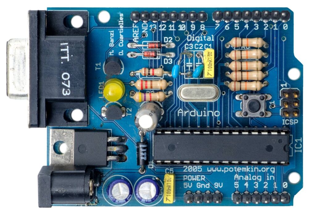
“On the original Arduino serial board, look at the components,” says co-founder David Cuartielles, talking about the earliest of Arduino’s self-assembly boards, which were used almost exclusively in the classroom. “They’re sorted by value. I made sure that components of a similar type and value were together, to minimize mistakes during assembly. For example, there were two diodes. In terms of operation, they’re working in opposite directions to each other. But to reduce errors when populating the board by hand, I set the diodes facing in the same direction, and the PCB’s tracks take care of orientation. So it’s optimized for education, not for electronic operation!”
“Back in the day we used to use FTDI chips,” Massimo recalls. “A Scottish company, now in Singapore. Great chips, but you had to install drivers to get your computer to recognize devices when you plugged them in.”
“Which is when we realized there was this thing called CDC (communications device class) protocol, which was embedded into operating systems. It’s the reason you don’t need a driver for a USB serial port. We found that you could develop a firmware for some simple Atmel processors that worked just the same as FTDI chips, but would liberate us from needing a driver.”
This opened the door to reprogramming the firmware and making the boards do other things. Some people created MIDI firmware to send notes to a computer. Others made HID firmware so they could emulate computer peripherals. It was the herald of dual processor experimentation, which piqued the interest of both Arduino users and its designers.
Press On with the UNO
These proto-UNOs also required you to press a reset button before uploading new code. It was a pretty standard requirement for any prototyping platform at the time. Most designers had simply never questioned this apparent necessity. But when the Arduino team found themselves placing more and more emphasis on user experience, this small requirement was identified as an obstacle to useability.
It was at a workshop in Germany when Massimo figured out an alternative.
“It turned out that if you put a capacitor between the reset pin of the microcontroller and one of the serial port pins,” he explains, “it would reset the board automatically whenever you opened the port.” This small tweak became a vital and very popular aspect of the UNO’s useability.
But there were a lot of other factors that went into making the UNO so recognizable that it’s become indistinguishable from the overall Arduino brand.
The Power of One
Early Arduino boards required a more active participation when it came to powering them up.
They already offered flexibility in choosing your power source. But if you wanted to power the board from the USB or the external power jack, you had to move a jumper. Not a lot to ask, but as many of the design experiments proved, these seemingly insignificant requirements had a disproportionate effect on usability.
People would forget to set the jumper in the first place. Or have it in the wrong position when trying to power on, and frustrations ensued. So a small circuit was implemented that detected where the power was coming from, and switched to it automatically. Simple, but essential.
Tweaks to the power options didn’t stop there. On other boards there had been some experimentation with microUSB ports, not realizing how fragile they can be. So when it came to the UNO, the USB connector was carefully chosen for its reliability. “It’s like a Russian tank,” Massimo laughs. “It’s indestructible.”
Feeling Blue
“Going from the original design we had on a rectangular green board, to the shaped blue board that everyone recognizes now, took two days,” David recalls, musing on how Arduino could move so fast because of its focus on simplicity. “And in between we went to a party. Because the designs are very simple.”
“The original board, before it became the Arduino UNO, was a typical green PCB,” Massimo explains, lavishing mediocrity on the state of pre-Arduino prototyping platforms. “Not so exciting. The PCB manufacturer we were talking to went on and on about how he was making blue PCBs because they were apparently easier on the eye for production line workers. We thought, ‘Hey! Blue is better, because everyone else is using green!’”
You can see a pattern in the way Arduino was beginning to question the norms of its industry. Those shades of blue and teal have become synonymous with Arduino devices, and that didn’t happen by accident. At the time, PCBs were green. Maybe beige, if they were still bare fibreglass.
But no longer, once the UNO arrived.
Arduino didn’t just have its eye fixed on usability. It was also searching for an identity that makers would associate with enhanced experience and quality. It just so happened that the UNO was destined to become the vessel that gave that identity a tangible shape.
Taking Shape
“I was teaching and I had to draw PCBs on a white board all the time,” recalls David. “And all boards were square or rectangular. So how do you tell people which is left and which is right? In order to avoid errors in plugging things in and building the boards, which originally were self-assembly, I thought it needed to be a non-symmetrical shape. Then the students could see that this is left and this is right. It wasn’t a creative decision, so much as a functional one for education purposes.”
Around that same time, the school where he was teaching in Ivrea was issuing everyone with business cards. They arrived on Massimo’s desk in a small plastic box. “So that seemed like a good starting place for sizing,” Massimo remembers, “as it seemed like a great idea if we could fit the UNO in a plastic box like the one my business cards came in.”
It was taking shape as a very recognizable product. And you want to put your name on products you’re proud of. Typically any branding on a PCB was added using the standard font that came with the Eagle PCB design software. Essentially vector lines, not graphics. This change was enacted by a former student of the Ivrea classroom, Giorgio Olivero. He was entrusted with the new Arduino identity.
“The strength of our current image depends entirely on the outstanding work Giorgio’s done,” David notes. “Giorgio understands not only graphic design, but the importance of designing the whole user experience. He understood interaction design really well. He understood the nature of the Arduino project intimately, and the needs of the end user.”
The UNO was the moment when quality came home in every respect. The boards were given an appealing new color, precision engineering, high quality manufacturing, and an emblem that made sure you knew you were holding an Arduino.
“The response was fantastic,” David continues, reflecting on the reception that the new Arduino and its flagship device received. “Nowadays it’s really common to do these kinds of things, but back then on the maker scene it was really unusual to put so much into making things look good, and putting a focus on the user experience.”
One Small Mistake
“When I was designing the board I made a mistake that we still have to live with,” admits Massimo. “I moved the connectors in the top right of the board half a step to the left, so the gap between the connectors is non-standard. It’s 1.27mm out. Which is fine on the connectors at the bottom, but that’s why you struggle to use a veroboard to develop shields, because the connectors aren’t quite aligned as they were meant to be.”
It’s a mistake that had a silver lining, though. That slight misalignment also (inadvertently, perhaps) gave us a key for attaching shields the right way around. So, just between you and me, let’s pretend it was deliberate and say no more about it.
Even the first batch of UNOs that came off the production line weren’t quite where Arduino wanted them to be, quality wise. The process for milling the PCBs into the iconic UNO shape wasn’t as reliable as it is now.
A small number of the boards had rough edges where they were snapped out of the sheet after cutting. Nothing that affected the operation of the board, but not so good when your focus is on achieving a distinctive level of quality.
“A friend and I spent the weekend at the PCB manufacturers,” Massimo remembers, semi-fondly, “sandpapering the edges of the first batch of UNO boards. What else could we do?”
Ten Thousand and UNO
Makers responded very positively to the ethos behind the UNO. And that enthusiasm was directly reflected in the number of Arduino boards sold.
“I remember an article in a magazine celebrating that Arduino had sold 10,000 boards,” Massimo recalls. “Arduino was here to stay, they said, because back then if anyone sold 10,000 boards you were boss!”
Arduino itself celebrated this milestone back in 2007, with a predecessor to the UNO called the Arduino Diecimila, meaning “ten thousand”. Interestingly enough, this was also the board that introduced automatic software resets when uploading a sketch, so you no longer had to press a reset button. Without the Diecimila, the UNO couldn’t have been born.

Now Arduino’s selling in the region of 10,000 boards a week. As you can imagine, magazines and blogs have stopped writing about every maker device that hits the 10,000 milestone now. The UNO itself, in fact, has recently crossed the 10 million mark.
The Day of the UNO
It wasn’t just the Arduino UNO that was unveiled at the Maker Faire New York in 2010. It was the new Arduino. Colors, branding, logos and a refined focus on usability and recognizable quality across everything Arduino did, from the UNO to the website and the packaging.
“I was the only one not present at that event in New York,” David laughs. “I was in a hotel in my home town of Malmö, because I had to launch the new website. At the time we were running the whole Arduino server in a $5-per-month VPS, because we had no money. Whenever we announced a new product, the website was going down. So to try and avoid this happening while Massimo was up on stage announcing the Arduino UNO, I was waiting to flip the website to Giorgio’s fantastic new design.”
The UNO’s launch signaled a transition from DIY success story to the primary platform for makers, engineers and creators around the world.
“We didn’t create a computer that allowed people to continue to do their job but at a cheaper price,” David continues. “We created a computer that empowered people who had no idea about electronics to start using technology, and this represented a huge life change for a lot of people. When I hear people say they started with an Arduino UNO, and now they’ve become the IT teacher at their school, it’s just amazing. And there are hundreds of stories like this.”
“There are some products in history that just work,” Massimo concludes. “That simply do what people need. So they endure. They last for a long time.”
He’s talking about the UNO. And its story hasn’t finished yet, as the iconic board was recently re-imagined as the stunningly beautiful UNO Mini Limited Edition.
You can follow any responses to this entry through the RSS 2.0 feed. You can leave a response, or trackback from your own site.